1
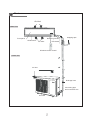
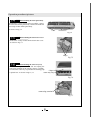
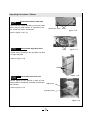
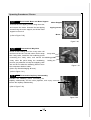
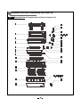
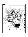
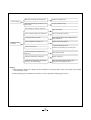
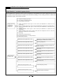
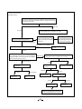
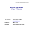
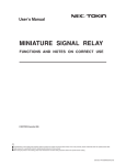
1 Summary and features TECHNOLOGY ULTIMATE COOLING & HEATING SOLUTION 3 Part name Air inlet Indoor Unit Receiving window Front panel Guide louver Air outlet wrapping tape LED board Wireless remote controll Outdoor Unit Air inlet Drainage hose Connecting pipe and connection wire Air outlet 4 Overall and Installing Dimension Overall and Installing Dimension of Indoor Unit U Air inlet grill Left piping hole Right pipinghole Top view Unit? mm Rear view Wall-mounting plate Overall and Installing Dimension of Outdoor Unit U Unit: mm Bolt Nut Wrench 6 Function manual and operation method of remote controller Function manual of remote controller This function manual is applicable to D.C. Variable Frequency Linge Wind Series:GWHD12A6ND31A 6.1.1 Temperature parameters ƹ Room set temperature (Tset) ƹ Room ambient temperature (Tamb) 6.1.2 Fundamental functions After powered on, no matter when the compressor is started, the time interval between two startups cannot be less than 3 minutes. 6.1.2.1 COOL mode 6.1.2.1.1 The condition and process of cooling If TambTset, COOL mode will act, the compressor and outdoor fan will run, and the indoor fan will run at the set speed. If TambTset-2ć, the compressor will stop, the outdoor fan will delay 30 seconds to stop, and the indoor fan will run at the set speed. If Tset-2ć˘Tamb˘Tset, the unit will keep running in the previous mode. In this mode, the reversal valve will not be powered on and the temperature setting range is 16ć~30ć. The unit will adjust the running frequency of the compressor automatically according to the change of ambient temperature. Tset Start cooling Tamd Original running state Tset Stop cooling 3min Compressor Outdoor fan Indoor fan Set fan speed 6.1.2.1.2 Protection function Stop Run ƹ Antifreezing protection Under cooling and drying mode, after the compressor run about 10mins,when the pipe temp.of the evaporator is to low, the compressor will stop, the outdoor fan will stop after 30s, under cooling mode the indoor fan and swing motor will keep running in the original mode , under drying mode the indoor fan will run at low fan speed, the swing motor will run in the original mode. When antifreezing protection is eliminated and the compressor has stopped for 3 minutes, the unit will resume running in the original mode. The period of antifreezing protection Compressor ı3 min Outdoor fan Indoor fan Stop Run ƹ Overcurrent protection If total current is high, the compressor will run in limited or dropped frequency. When total current goes on rising over the stated value, the compressor will stop, the outdoor fan will delay 30 seconds to stop. 6.1.2.2 DRY mode 6.1.2.2.1 The condition and process of drying If Tamb>Tset, DRY mode will act, the indoor fan, outdoor fan and compressor will run, and indoor fan will run at low speed If Tset-2ćTambTset, the unit will keep running in the original mode. If Tamb<Tset-2ć, the compressor will stop running, the outdoor fan will delay 30 seconds to stop and the indoor fan will run at low speed. ¾In this mode, the reversal valve will not be powered on and the temperature setting range is 16ć~30ć. The unit will adjust the running frequency of the compressor automatically according to the change of ambient temperature. T Dry mode will act amb Tset Running in the original mode Tset-2Ɔ Stop running Compressor Outdoor fan Indoor fan Low fan speed 6.1.2.2.2 Protection Stop Run Protection is the same with that in COOL mode. 6.1.2.3 HEAT mode 6.1.2.3.1 The condition and process of heating If TambTset+2ć, HEAT mode will act, the compressor, outdoor fan and 4-way valve will run simultaneously, the indoor fan will delay at most for 2min to run. If Tset+2ć⧞Tamb⧞Tset+5ć,the unit will keep running in the original mode. If TambTset+5ć, the compressor will stop, the outdoor fan will delay 30sec to stop and the indoor fan will blow for 60sec at the original speed and then stop. ¾In this mode, the temperature setting range is 16ć~30ć. ¾The air conditioner will adjust the running frequency of the compressor automatically according to the change of ambient temperature. ¾When the unit is turned off in HEAT mode, or switched to other mode from HEAT mode, the four-way valve will be powered off 2min later after the compressor stops. Stop heating Tset Original running state Tset Tamb Start heating 3min Compressor Outdoor fan Indoor fan 2min 2min Reversal valve Stop Run 6.1.2.3.2 The condition and process of defrosting When frost is detected in the condenser, the system will enter into defrosting state. When defrosting starts, the compressor and indoor fan will stop, and the outdoor fan and four-way valve will delay 30 seconds to stop. The compressor will start again after 30s and. When the compressor has run for 8mins, the compressor will stop. After 30 seconds the four-way valve opens and after another 60 seconds, the compressor and outdoor fan resume running. The indoor fan will delay 2 minutes to run at the latest and temperature on the display panel shows H1. Under heating mode,when the compressor is stopped by malfunction, the indoor fan will blow at low fan speed for 60s and then stop. 6.1.2.3.3 Protection Overcurrent protection If total current is high, the compressor will run in limited or dropped frequency. When total current go on rising over the stated value, the compressor will stop, the outdoor fan will delay 30 seconds to stop. 6.1.2.4 FAN mode In this mode, the indoor fan will run the fan in High, Med, Low and Auto mode. The compressor, outdoor fan and four-way valve will stop. In this mode, the temperature setting range is 16~30 . The unit will adjust the running frequency of the compressor automatically according to the change of ambient temperature. 6.1.2.5 AUTO mode In this mode, the system selects COOL, HEAT and FAN mode automatically according to the change of ambient temperature. The protection function is the same with that of COOL/HEAT mode. The unit will adjust the running frequency of the compressor automatically according to the change of ambient temperature. 6.1.3 Other control 6.1.3.1 ON / OFF Each time the On/Off button of the remote controller is pressed, the On/Off state will switch once. 6.1.3.2 MODE selection Press the MODE button on the remote controller to select and display the following modes: AUTO, COOL, DRY, FAN, and HEAT. 6.1.3.3 TEMP. setting button Each time TEMP + or TEMP - button is pressed, the set temperature will be increased or decreased by 1 . Adjusting range is 16~30 . In AUTO mode, this button does not function. 6.1.3.4 AUTO key When the unit is stop, press AUTO key,the unit will run under AUTO mode and the swing motor starts. AUTO/STOP When the unit is running, press AUTO key,the unit will be stopped. 6.1.3.5 Timer control The unit is turned on or off according to the timer set by the remote controller. Handling switch 6.1.3.6 Sleep control When the air conditioner is in COOL or DRY mode, after Sleep mode has been set properly, the preset Tset will be increased by 1 ć after the sleep program has run for 1 hour, and Tset will be increased by another 1ć after 2 hours. Tset has been increased by 2ć totally in two hours. Then the unit will run at this set temperature and at the set speed. Tset+2ć Set temp.Tset Tset+1ć Tset 1h 2h Above 2h When the air conditioner is in HEAT mode, after Sleep mode has been set properly, the preset Tset will be decreased by 1ć after the sleep program has run for 1 hour, and Tset will be decreased by another 1ć after 2 hours. Tset has been increased by 2ć totally in two hours. Then the unit will run at this set temperature and at the set speed. 1h 2h Above 2h Tset Tset-1ć Tset-2ć In AUTO or FAN mode, the setting temp. will not change. Set temp.Tset 6.1.3.7 Indoor fan control Use the remote controller to set the indoor fan running at HIGH, MED or LOW speed. At this time the fan will run at high, medium or low speed. It can also be set to AUTO and the indoor fan will select fan speed(HIGH, MED or LOW) automatically according to ambient temperature. There are at least 3mins and 30s delay for fan speed shift. 6.1.3.8 Power supply for outdoor unit The power supply for outdoor unit is turned on in AUTO, COOL, HEAT and DRY mode under turn-on state. The power supply for outdoor unit will delay 3 minutes to turn off under turn-off state or in the FAN mode under turn-on state. 6.1.3.9 Swing control Use the SWING button of the wireless remote control to control SWING On and Off. Swing will only act when indoor fan is running.After power on, the swing motor turns back to 0 position and closes the air outlet vent; if it does not preset swing, after the unit is turned on, it will turn to the max. air outlet D1 position; then turn back to L position under COOL mode.Under HEAT mode,the guide louver stays at D1;when in swinging state, it will swing between L1 and D1 position. When the unit is turned off, it will turn back to 0 position. 6.1.3.10 Buzzer control When the unit is power on or receives remote control signal or the auto key be pressed,the buzzer will give out a beep. 6.1.3.11 Power-off memory function Contents of memory: Mode; Swing; Set fan speed, Set temperature,Timing etc. Under turn-on state, when power off and power on, the power supply for outdoor unit will be turn on after 3mins . Under turn-off state, when power off and power on, the power supply for outdoor unit will be turn on immediately. 6.1.3.12 Delay Protection of Compressor Under COOL; DRY; HEAT mode, before each time the compressor starts, there will be 3mins delay. 6.1.4. Common protection function in each mode 6.1.4.1 Overload protection Ttube:at cooling,it detects the temp. of outdoor heat exchanger,at heating,it detects the temp. of indoor heat exchanger. When Ttube is detected high, the compressor will run in limited frequency.When Ttube goes on rising over the stated value, the compressor will stop, under AUTO HEAT or HEAT mode, indoor fan will blow 60s at low fan speed and then stop, under other mode, the indoor fan will run at set speed. 6.1.4.2 Compressor discharge temperature protection When discharge temperature is too high to over the stated value, the compressor will stop, and When discharge temp. resume normal and the compressor has stopped for 3 minutes, the unit will resume its original operating status. 6.1.4.3 Communication malfunction When not receiving correct signal for 3 minutes, the unit has communication malfunction and the outdoor unit stops, it is the same as normal stop when meeting the set temp.. 6.1.4.4 Module protection When module is in protection, the compressor will stop, after the compressor has stopped for 3 minutes, it will resume to running. During module protection period, the indoor unit displays malfunction and the whole unit stops. 7 Disassembly procedures Disassembly procedures for indoor unit Operation procedures/pictures 8.1.1 Disassembling the front panel and electric box cover Unloose the clasps on both sides and lift the panel upward. Unplug the two connecting terminals of the display and slide out the rear clasp from the groove to take off the front panel.(you can use panel support bar to support the panel) Screw off the fixing screws of the electric box cover and open the electric box top cover to take it off. As shown in Fig.7-1 Panel panel sup- Screw port bar Fig.7-1 Filter Push the filter up to unloose the clasp to pull out the two filters. 8.1.2 As shown in Fig.7-2 Filters Fig.7-2 Disassembling the guide louver Bend the guide louver with strength and let out the rotating shaft from the groove to take off the guide louver. As shown in Fig.7-3 Guide louver Fig.7-3 Electric box top cover Operation procedures/pictures Disassembling the front panel body Unclench the 3 screw covers and screw off the 3 pieces of screws that fix the panel body. Unloose the front and rear clasps to take off the panel body. As shown in Fig.7-4 screw screw covers Fig.7-4 Disassembling the electric box cover Unloose the 3 clasps to take off the electric box cover. As shown in Fig.7-5 cl clasps Fig.7-5 Disassembling the water-tray assy Unloose the clasp on the left side and unplug the connecting terminal of the stepping motor. Carefully to remove the water-tray assy because the drainage pipe clasp water-tray assy is placed here. As shown in Fig7-6, 7-7 Fig.7-6 cc connecting terminal Fig.7-7 Operation procedures/pictures Disassembling the electric box 7.1.7 Screw off the two pieces of screws that fix the electric box and unloose the clasp. Pull out the tube sensor, unloose the grounding nut and unplug the motor connecting terminal take out the electric box. As shown in Fig 7-8 7.1.8 ||||||||| Tube sensor Screws Grounding nut Motor connecting terminal Fig 7-8 Disassembling the evaporator assy Screw off the screws that fix the evaporator, one piece on the left and two pieces on the right. As shown in Fig 7-9, 7-10 Lift the left end of the evaporator slightly upward with your end and push it rearward to let out the side clasps of the evaporator from the groove. Take out the evaporator carefully and pay attention to protecting the connecting pipe. Screw Fig 7-9 Screws Fig 7-10 7.1.9 Disassembling the motor Screw off the 3 pieces of screws that fix the motor clamp to take off the motor clamp. As shown in Fig.711 Screw off the fixing nut that fixes the cross flow fan to pull out the motor from the cross flow fan. As shown in Fig.7-12 Screws Right motor clamp Fig 7-11 screws 7.1.10 Disassembling the cross flow fan Refer to the above steps to take out the cross flow fan from the base plate after taking out the motor. motor cross flow fan s Fig 7-12 Disassembly Procedures for Outdoor Unit Operating Procedures / Photos Disassemble Top Cover and Handle Use screwdriver to unscrew the screw at the handle, and remove the handle. Unscrew the three screws around the top cover, and remove the top cover. (refer to Figure 7-13) Top Cover screw screw Handle Figure 7-13 Disassemble Rear Grill Screw out the 4 self tapping screws on rear side plate and chassis of valve supporter and side plate of condenser can take off rear grill. screw (refer to Figure 7-14) Grill Figure 7-14 2 Disassemble Components of Panel Screw out the 5 tapping screws on panel and chassis of valve supporter and side plate of condenser can take off components of panel. Panel screw (refer to Figure 7-15) Figure 7-15 Operating Procedures / Photos Disassemble electric install plate Screw out the 3 bolts that fixing on electric install plate, plug out lead inserter of compressor and fan to take off electric install plate. electric box cover bolts Figure 7-16 (refer to Figure 7-16,7-17) Disassemble Right Side Plate bolts Figure 7-17 Screw out the 5 bolts on rear side plate can take off right side plate. (refer to Figure 7-18) bolts Figure 7-18 Disassemble axial-flow vane Loosen tighten nut by spanner to take off nuts, spring washer, flat washer, and take off axial-flow vane forcibly. tighten nut (refer to Figure 7-19) axial-flow vane Figure 7-19 Operating Procedures / Photos Disassemble Motor and Motor Support Motor Support Unscrew the four tapping screws fixing the motor, and remove the motor. Unscrew the two tapping screws fixing the motor support, and lift the motor support to remove it. tapping screws Motor (refer to Figure 7-20) Figure 7-20 Disassemble 4-Way Valve Screw off the holding nut of the 4-way valve coil and remove the coil. Use wet cotton cloth to wrap 4-way valve the 4-way valve, unsold the four soldering points connecting the 4-way valve, and remove the soldering points holding nut 4-way valve. Be quick during the unsoldering process, pay attention to keep the wrapping cloth wet and do not allow the soldering flame to burn the compressor lead-out cable. (Note: only after discharging all freon). Figure 7-21 (refer to Figure 7-21) Disassemble Capillary Subassembly Unsolder the soldering points connecting the capillary subassembly and the other pipelines, and remove the capillary subassembly. Capillary Subassembly (refer to Figure 7-22) Figure 7-22 Operating Procedures / Photos Disassemble Valves Unscrew the two screws fixing the big valve, unsolder the soldering point between the big valve and the return-air duct and remove the big valve. (Note: when unsoldering the soldering point, use wet cloth to completely wrap the big valve to prevent valve body from being harmed by high temperature.) Unscrew the two screws fixing the small valve, unsolder the soldering point connecting the small valve and the fork type pipe, and remove the small valve. (refer to Figure 7-23) Small Valves Big Valves bolts Figure 7-23 Disassemble Compressor Unscrew the three nuts with washers at the foot of the compressor. Unsolder the soldering points at the suction and the discharge pipes of the compressor, carefully remove the pipes and take out the compressor. (refer to Figure 7-24) Figure 7-24 compressor bolt 8 Exploded View and Components and Parts List Exploded View of Components and Parts of Indoor Unit Exploded View of Outdoor unit 9 Troubleshooting Common section Analysis in this section is used for Linge Wind D.C. Variable Frequency Series. Before analysis, you can diagnose according to the code displayed on indoor unit or indicator display on outdoor unit. (Refer to 9.2 Malfunction display section). When the breaker is set ON, it will trip at once Measure the insulating resistance for grounding to confirm whether there is electrical leakage or short circuit in the unit When the unit is turned on, the breaker will trip in a few minutes Insulation malfunction of line or componen in the air conditioner. Insulation breakdow occurs after radiation, which causes shor circuit or electricity leakage. Measure insulating resistance or use one-by-on elimination method; Malfunction of fuse. Replace it. Breaker tripped or fuse burnt out Air conditi oner cannot start up Air conditioner does not response after powered on. (The buzzer does not sound after the plug is connected and the unit does not response after the remote controller is used to turn it on) Remote controller does not receive signal (When powered on, the buzzer will send out a sound, unless it is broken) No power supply Check power supply circuit The power plug is not or poorly connected Check and plug well plug, make loosen contact firm Controller fuse is burnt out Change control fuse Loose or poor contact of transformer connection, or transformer malfunction Secure the wire connection: measure the output voltage of the transformer and replace it if the value is wrong The controller is broken Replace the controller Batteries of remote controller are low Change battery Malfunction of remote controller Loose or poor connection of receiving head Receiving head is broken First press the "AUTO" button of the manual switch. If there is no response, check according to the above method; if it is normal after the button is pressed, check if the installation location and wire connection of the receiving head are correct. If correct, replace the receiving head, or the remote controller. Improper setting of temperature Adjust the set temperature Whether cooling (heating) load is proper Check the estimated load of cooling (heating) Poor cooling (heating) effect Malfunction of refrigerant flow Leakage or shortage of refrigerant Vacuumize after leakage detection and leakage repair. Charge refrigerant according to specification. Leakage occurs between high and low pressure inside compressor Replace the compressor Malfunction of four-way valve Replace the four-way valve Partial blockage of capillary Replace the capillary Blockage of cooling system Use the method of observing condensation on the evaporator and pressure value of high pressure manometer to see whether the system is blocked and carry out corresponding handling on the system Poor thermal insulation of connecting pipe of indoor and outdoor unit Air circulation is insufficient Ensure that both thick pipe and thin pipe are insulated well. The exposed part of the connector and copper pipe must be insulated as well. Heat exchanger of outdoor unit is blocked Clean the dust accumulated on the surface of the heat exchanger Air filters are blocked Clean the filter Fan speed is set too slow Set the fan speed to high or medium speed Fan speed turns low Improper installation location for outdoor unit Damage of capacitor damaged Replace capacitor Damage of motor Replace the motor the Outdoor unit should be installed in a place with well ventilation Outdoor temperature is too high Flashing or awning can be installed appropriately. If the max. cooling capacity cannot be satisfied, replacement of the air conditioner is recommended. Indoor sealability is inadequate; too many people go in and out frequently; there is heating unit in the room. Maintain a certain degree of indoor sealability. Try not to use appliance with high amount of heat. When unit is cooling or heating, both compressor and outdoor fan don't run When unit is cooling or heating, the compressor runs but outdoor fan doesn't run When cooling or heating, outdoor fan runs, but compressor doesn't run. When cooling or heating, outdoor fan runs, but compressor doesn't run. Fan doesn't run when FAN mode is set Abnormal power supply of outdoor unit Check the circuit according to circuit diagram Damage of outdoor main control board Replace the main control board Breakage of outdoor power module Replace the power module Improper setting of temperature Adjust the set temperature Breakage of outdoor fan motor Replace the fan motor Wrong wire connection Wire according to the circuit diagram Breakage of outdoor main control board Replace the main control board Breakage of outdoor fan capacitor Replace the fan capacitor Malfunction of compressor Replace the compressor Poor contact of connection between the main control board and module Re-fasten the connection Abnormal input of power module Check if input is 320V. If not, replace the rectifier Abnormal output of power module Replace the power module Compressor temperature is too high Cool the compressor for 30 min before running Wrong wiring Wire according to the circuit diagram Damage of outdoor main control board Replace the outdoor main control board Burn-out or broken wire of indoor fan motor Repair or change the fan motor Wrong wiring Wire according to the circuit diagram Circuit break or damage of fan motor capacitor Replace the indoor main control board Blockage or breakage of drainage hose Replace the drainage hose Wrap of refrigerant pipe connector is not tight enough Re-wrap and make it tight Fan of indoor unit contacts other parts Adjust fan location There is foreign substance in indoor unit Take out the foreign substance Compressor shakes too much Adjust support washer of the compressor and tighten loose bolts Touch of pipeline of outdoor unit Separate the touched pipeline Touch of inner plates 1. Tighten connecting screws 2.Stick shock-absorbing clay between plates Touch of outdoor unit fan blade with outer case Adjust louver position Abnormal sound inside compressor Replace compressor Abnormal electromagnetic sound inside four-way valve when heating Short circuit inside electromagnetic valve. Replace the electromagnetic valve Water leakage Abnormal sound and shake Notes˖ 1.When repairing, before the voltage between module PN is measured below 50V, do not touch any terminal to avoid electric shock. 2.When replacing power module and rectifier, be sure to spread the radiating paste evenly. 12.2 Malfunction display section Linge Wind D.C. Variable Frequency Series When malfunction or protection occurs in the air conditioner, corresponding code will be displayed on the screen of the indoor unit and the indicator of outdoor unit will blink accordingly as well. When protection or malfunction is eliminated, display will be back to normal E4: Compressor discharge protection E5: Low voltage overcurrent protection E6: Communication malfunction Display code and malfunction description of indoor unit F1: Indoor environmental sensor open or short circuit (the malfunction is detected for 30s continuously) F2: Indoor evaporator sensor open or short circuit (the malfunction is detected for 30s continuously) F3: Outdoor environmental sensor open or short circuit (the malfunction is detected for 30s continuously) F4: Outdoor condenser sensor open or short circuit (the malfunction is detected for 30s continuously) F5: Outdoor discharge sensor open or short circuit (after the compressor runs for 3 min, the malfunction is detected for 3s continuously) H1: Defrosting H3: Compressor overload protection H4: System malfunction (i.e. overload protection) H5: IPM module protection Indicator display of outdoor unit (Mainboard) Yellow light blinks 1 time Compressor is running (this is normal condition and the display of indoor unit is normal) (Mainboard) Yellow light blinks 2 times Defrosting (display H1) (Mainboard) Yellow light blinks 3 times Antifreezing protection (display of indoor unit displays is normal) (Mainboard) Yellow light blinks 4 times IPM module protection (corresponds to H5 of indoor unit) (Mainboard) Yellow light blinks 5 times Overcurrent protection (corresponds to E5 of indoor unit) (Mainboard) Yellow light blinks 6 times Overload protection (corresponds to H4 of indoor unit) (Mainboard) Yellow light blinks 7 times Discharge protection (corresponds to E4 of indoor unit) (Mainboard) Yellow light blinks 8 times Compressor overload protection (corresponds to H3 of indoor unit) (Mainboard) Red light blinks 1 time Limited frequency(current) (Mainboard) Red light blinks 2 times Dropped frequency (Discharge) (Mainboard) Red light blinks 3 times Limited frequency(overload) (Mainboard) Red light blinks 4 times Dropped frequency (Antifreeze Protection) (Mainboard) Red light blinks 5 times Malfunction of outdoor tube sensor (Mainboard) Red light blinks 6 times Malfunction of outdoor environmental sensor (Mainboard) Red light blinks 7 times Malfunction of outdoor discharge sensor (Mainboard) Red light blinks 8 times Starting temperature is reached. This is normal condition and display of indoor unit is normal (Mainboard) Green light blinks Communication is normal Indicator display of outdoor unit Note: Malfunction display : blind 0.5s; stop 0.5s, there is 2s' interval between two malfunction displays Analysis or handling of some of the malfunction display: 1. Compressor discharge protection (E4): Possible reasons: shortage of refrigerant; blockage of air filter; poor ventilation or air flow short pass for condenser; the system has noncondensing gas (such as air, water etc.); blockage of capillary assy (including filter); leakage inside four-way valve causes incorrect operation; malfunction of compressor; malfunction of protection relay; malfunction of discharge sensor; outdoor temperature too high. Handling method: refer to the malfunction analysis in the above section. 2. Low voltage overcurrent protection (E5): Possible reason: Sudden drop of supply voltage. 3. Communication malfunction (E6): Handling method: Check if communication signal cable is connected reliably 4 Sensor open or short circuit (F1, F2, F3, F4, F5): Handling method: Check whether sensor is normal, connected with the corresponding position on the controller and if damage of lead wire is found 5. Compressor overload protection (H3): Possible reasons: insufficient or too much refrigerant; blockage of capillary and increase of suction temp.; improper running of compressor, burning in or stuck of bearing, damage of discharge valve; malfunction of protector. Handling method: adjust refrigerant amount; replace the capillary; replace the compressor; use universal meter to check if the contactor of compressor is fine when it is not overheated, if not replace the protector. 6. System malfunction (H4): i.e. overload protection. When tube temperature (Check the temperature of outdoor heat exchanger when cooling and check the temperature of indoor heat exchanger when heating) is too high, protection will be activated. Possible reasons: Outdoor temperature is too high when cooling; insufficient outdoor air circulation; refrigerant flow malfunction. please refer to the malfunction analysis in the previous section for handling method . - - 7. Module protection (H5): Handling method: Check if the voltage between power module P and N is too low and if the current is too high. In normal condition, voltage between P and N should be about 320V. Abnormal Check power supply circuit of outdoor unit (if PTC resistance rectifying bridge, reactor, capacitance etc. is ok). Normal Check if radiating paste is spread evenly or radiating sticker is stuck well; if screws of power module is tightened Temperature of power module is too high, which causes overheating protection Reinstall power module and re-spread radiating paste or stick radiating sticker on the radiator of power module. Protection is still displayed Confirm the setting status of outdoor unit (cooling) Poor radiation, heat exchanger is dirty Remove obstructions and clean Normal Confirm if outdoor fan motor is running; unplug the three connecting wires between U, V, W of compressor Outdoor fan runs and power module. Turn on the unit to see if outdoor fan runs normally (about 1 minute) Confirm if there is voltage output and balance of voltage between any two phases of U, V and W. Outdoor fan stops Measure the voltage of outdoor fan connector No Yes Whether module type is correct Abnormal No voltage Replace the mainboard of outdoor unit Replace the power module Normal Normal voltage Replace the fan motor Replace the module with correct type Measure the three-phase resistance of compressor Normal Whether cylinder of compressor is stuck If the unit runs normally after connected with the new compressor for trial run, the cylinder of original compressor is stuck Abnormal Replace the compressor