1
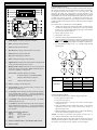
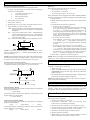
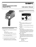
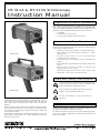
DT-311A & DT-315A Stroboscope
Instruction Manual
Inspection/Standard Accessories
If upon delivery shipping damage is detected, do not operate the
unit. Notify shipping carrier immediately for damage claim
instructions. Refer to nameplate and record serial number for future
reference. Items included with the DT-311A/DT-315A are:
• (1) Handle
• (1) Flash tube removing tool
• (1) AC charger/adapter (Model 315A only)
Features and Benefits
DT-311A
Shimpo’s DT-311A and DT-315A stroboscopes/digital
tachometers incorporate the latest microprocessor technology for
visual inspection applications:
• Aluminum construction provides exceptional durability
• High polish and focused reflector eliminates “blind”
viewing areas
• External trigger allows unit to be automatically
synchronized with equipment
• Continuous duty cycle eliminates need to shut down for
cooling
• Phase shift allows visual analysis of rotating/reciprocating
objects
• High accuracy ( ±0.01% of reading ) is ideal for QC
inspection and process control
• Synchronous output enables strobe to drive other strobes
• Flash timer control conserves flash tube life
Important Safety Instructions
Do not operate or store instrument in the following places:
explosive areas; near water, oil, dust, or chemicals; areas
where temperature is above 104°F (40°C).
DT-315A
Do not look at the emitted light for long periods
of time; it can be harmful to the eyes.
Do not disassemble or repair unit while in
operation.
Congratulations on your purchase of a Shimpo DT-311A or
DT-315A stroboscope/digital tachometer. We trust you will
enjoy many years of professional results from your Shimpo
product.
Please read the entire instruction manual thoroughly before
initial set-up and operation; the information contained herein
will aid you in operating your Shimpo stroboscope safely and
with excellent results.
If you have any questions regarding our product(s), call your
local Shimpo representative or contact Shimpo Instruments
directly for assistance.
Set-up
The DT-311A and DT-315A may be operated handheld or else
mounted on a tripod for added convenience.
To mount the strobe on a tripod (or any other mounting surface),
use screw ¼ -20unc, length 8mm or shorter for the tripod screw
hole on the bottom.
Display P
anel
1
4
2
3
1.
LED display: Displays function and value
2.
EXT: External mode indicator
3.
INT: Internal mode indicator
4.
B-CH: Battery charge indicator (DT-315A only)
5.
FPM: Flash per minute indicator
6.
deg: Phase shift degree indicator
7.
mSec: Millisecond delay time indicator
8.
Signal switch: Switches the unit from the external mode
to the internal mode (and vice-versa)
9.
Display mode switch: When unit is set to the external
mode, the strobe will switch to RPM (FPM)/deg/msec
each time “MODE” is depressed
Operation
True RPM Measurement
Shimpo stroboscopes are DUAL function instruments that give
the operator the illusion of “stopped motion” where in actuality
the equipment under observation is in a moving state. By
adjusting the flash rate, equipment in motion appears to be
standing still. With a slight adjustment, movement can be viewed
in apparent slow motion, which enables the operator or observer
to study the process in action. All Shimpo stroboscopes can
measure rotational (RPM) or reciprocating (strokes per minute)
speeds with the same high precision as with an electronic digital
tachometer.
To measure true revolutions per minute (RPM):
1. “Mark” the object to be measured by either visually noting
an inherent distinguishing characteristic (such as a label,
scratch, etc.) or physically marking the object with a small
piece of tape, pencil mark, etc.
2. Firmly plug in power cord.
3. Turn power switch on.
4. Turn setter from highest FPM downward.
5. The true RPM can be noted once the action appears frozen
and the first single image of the “mark” appears (see chart
below and accompanying diagram for further explanation).
6. To verify RPM reading, press “÷2”; a single image should
appear again.
RPM (FPM) Displays flashes per minute
External input 0-35,000 RPM (FPM)
deg
Displays flash delay in degrees
msec
Displays flash delay in msec
10. Setter: Changes the flashing rate
11. (x2) Switch: In the internal mode, pressing “x2”
doubles the flashing rate
12. (+) Switch: In the internal mode, when object appears
to be standing still, pressing “+” will give the illusion
that the object is moving towards the rotating direction
at a speed of 1 rotation in 6 seconds
13. (÷2) Switch: In the internal mode, pressing “÷2” divides
the flashing rate by two
14. (-) Switch: In the internal mode, when object appears
to be standing still, pressing “-“ will give the illusion
that the object is moving in reverse at a speed of 1 rotation
in 6 seconds
15. Input and output connector:
PIN #1:
+12V
PIN #2:
Synch output signal
PIN #3:
Input signal
PIN #4:
0V
16. Power cord (DT-311A) / AC adapter (DT-315A)
17. Power switch
Shaft Rotation
(RPM)
At 1,500 RPM
Flashes
(RPM)
Flashes/
RPM Shaft
Stopped
Images
6,000
4 times
4
4,500
3 times
3
3,000
2 times
2
1,500
1 time
1
750
1/2 time
1
500
1/3 time
1
Internal Triggering Mode
To operate the stroboscope in internal triggering mode:
1. Firmly plug in power cord.
2. Turn power switch on.
3. If internal indicator is not on, press “SIG”; the INT light
will then turn on.
4. Aim light beam at object under observation. The optimal
distance between the strobe and moving object is
approximately 2 feet.
5. Measure RPM by turning the setter to adjust the flashing
rate to the rotational speed of the object.
NOTE: To achieve a particular rate quickly, use the “x2” or
“÷2” switches and then the setter for fine tuning.
NOTE: Once the internal timer has expired, the strobe will stop
flashing and the display will flash rapidly. To restart the strobe,
turn power switch off, then on, and the cycle will repeat.
Operation
External Triggering Mode
To operate the stroboscope in external triggering mode:
1. Connect external trigger or sensor wires according to
connector pin designation:
1
+12V (for powering sensor)
2
Synch output signal
2.
3.
4.
5.
3
External input signal
4
0V (common)
Firmly plug in power cord.
Turn power switch on.
If INT lamp is on, press “SIG” until EXT lamp turns on.
Press “MODE” to select proper mode:
FPM Light will flash in correspondence with input signal;
the input signal will be calculated into FPM and
displayed.
deg One cycle of input signal is 360°. A delayed angle
will be displayed from 0 up to 359°. (The delayed
angle can be changed by turning the knob setting as
previously described).
msec The above delayed angle will be displayed in msec.
NOTE: If the input signal frequency exceeds upper or lower
limits, the alarm dashes (-----) will be displayed and the strobe
will stop flashing.
NOTE: Once the internal timer has expired, the strobe will stop
flashing and the display will flash rapidly. To restart the strobe,
turn power switch off, then on, and the cycle will repeat.
Synchronous Output Signal
For triggering and controlling additional stroboscopes, the
synchronous output signal appears on pin #2 (see below).
Memory
The following parameters are set at the factory:
• Decimal point: autorange
• Internal timer: continuous
• External trigger edge: L-H (Lo to Hi)
These parameters can be changed in the field to facilitate different
situations. To change any of the above parameters, follow these steps:
1. Turn power on.
2. Make sure that INT lamp is on. If not, press “SIG” until it
turns on.
3. Change the desired memory parameter:
a. To change the decimal point
Press “÷2” and “-“ at the same time for approximately
2 seconds until display alternates between —1— and
0.0. Press “+”. The display will freeze and show 0.0.
Change decimal point accordingly by pressing “+”. If
0.0 is selected the decimal point is in the autorange
mode. If 0 is selected the decimal point is eliminated
throughout the entire range.
b. To change the internal timer
Press MODE. The display will alternate between
—2— and 0; press “+”. The display will freeze to 0.
Use the setter to set timer anywhere between 1 and 120
minutes.
c. To change the trigger edge or the external mode
Press MODE. The display will alternate between
—3— and L-H. The external trigger edge is set from
the factory to occur during the positive transition of the
incoming pulse. To change it to the negative transition,
press “+”. Display will change from L-H to H-L.
4. Press “SIG” to go back to normal operation.
NOTE: the above settings can be checked quickly by performing
steps A to C as described above and then pressing “SIG”.
Battery Charge
(DT-315A Only)
If battery is low, “LLLLL” is displayed and display will eventually
disappear. Charge battery as follows:
1. Turn power off.
2. Insert AC adapter/charger plug into the strobe receptacle
(CAUTION: charge the unit only with the provided AC
adapter/charger).
3. B-CH lamp will be lit during battery charge; within 2 hours
the battery should be charged completely.
NOTE: The adapter/charger may be used as a power supply to
power the strobe continuously.
Battery Replacement
(DT-315A Only)
FPM Display Mode
If the input signal exceeds 585Hz, the upper dashes on the digital
display will be flashing:
----- upper dashes
If the input signal is lower than 0.67Hz, the lower dashes on the
digital display will be flashing:
----- lower dashes
The life of the built-in battery should last for approximately 300
charges. If the time period between recharges becomes
increasingly shorter, then replace battery with a new one.
Deg/msec Display Mode
If the input signal exceeds 167Hz, the upper dashes on the digital
display will be flashing:
(deg)
----upper dashes
----(msec)
If the input signal is lower than 0.67Hz, the lower dashes on the
digital display will be flashing:
(deg)
----lower dashes
----(msec)
1. Unplug line cord from power line.
2. Turn power switch off (wait a few minutes until
stroboscope is cool before proceeding).
3. Remove protective window by removing the 4 screws.
4. Use tube removing tool provided: insert tool all the way
and turn clockwise until tool locks. Pull out tube.
5. Install new flash tube using the removing tool.
6. Replace protective window.
7. Mount reflector in the center so that the reflector will not
interfere with the screw spacer on the corners.
Flash Tube Replacement
When FPM reading is displayed but unit is not flashing, flash
tube may need to be replaced:
Troubleshooting
FPM reading is displayed but unit is not flashing:
• Flash tube may need to be replaced (see "Flash Tube
Replacement" section)
Stroboscope is in external trigger mode, no flash:
• Check flash tube. Replace if necessary
• Check for damaged wiring and/or loose pin connections
Stroboscope is in internal trigger mode, no flash:
• Check flash tube. Replace if necessary
• Check for damaged wiring and/or loose pin connections
Dimensions & Specifications
DT-311A
Model
INTERNAL MODE
Flashing R
ange
Range
Accuracy
R esolution
Phase Shif
Shiftt
Display Update Time
Output Signal
Rate Multiplier/Divider
EXTERNAL MODE
Flashing R
ange
Range
Accuracy
Phase Shif
Shiftt
Delay Time
Exter
nal TTrigger
rigger Input Signal
External
Input Impedance
GENER
AL
GENERAL
Display
Flash TTube
ube P
ower/Life
Power/Life
Flash Duration
Sensor P
ower Supply
Power
Low Batter
Batteryy Indicator
Power R
equirement
Requirement
Operating TTemperature
emperature R
ange
Range
Weight
Dimensions
Wa r r a n t y
Standard Accessories
Optional Accessories
DT-315A
S T R O B O S C O P E
DT
-311A
DT-311A
S P E C I F I C A T I O N S
DT -315A
40.0 - 35,000 FPM (flashes per minute)
±0.01% of reading
0.1 FPM: 40.0 - 4,999.9 FPM
0.2 FPM: 5,000 - 7,999.8 FPM
0.5 FPM: 8,000 - 9,999.5 FPM
1 FPM: 10,000 - 35,000 FPM
Use +/- push buttons (360° in 6 seconds)
0.2 sec approx.
Synchronous, 400 msec. Pulse output, 0 to +12 VDC amplitude(approx.), 4.7 KΩ impedance
Multiply by 2, divide by 2
0.0 - 35,000 FPM
±0.01% ±1 digit
0 - 359° with 1° resolution
0 - 2,000 msec from 40 - 10,000 FPM
LO level: 0 - 0.8 VDC, HI level: 2.5 - 12 VDC or open collector (NPN), pulse width 50 msec min.
4.7 KΩ at 12 V / 6.8 K Ω at 0 V
5 digits, 0.4" (10 mm) high, LED
Xenon, 10 W max. (100 million flashes)
10 - 40 msec
12 VDC (40 mA)
Display shows all L’s
115 VAC or 220 VAC ±10% 60/50 Hz, 30 VA (specify voltage)
32° - 104°F ( 0 - 40°C )
2.6 lb (1.2 kg)
7.28"L x 4.72"W x 4.72"H (185 mm x 120 mm x 120 mm)
1 year
Handle, flash tube removal tool
Car rying case
Internal Battery Pack
4.4 lb (2 kg)
9.84"L x 4.72"W x 4.72"H (250 mm x 120 mm x 120 mm)
Handle, flash tube removal tool and AC charger/adapter
Warranty
LIMITED EXPRESS WARRANTY: Shimpo Instruments warrants, to the original purchaser of new products only, that this product shall be free from defects in workmanship and materials under normal use
and proper maintenance for one year from the date of original purchase. This warranty shall not be effective if the product has been subject to overload, misuse, negligence, or accident, or if the product has been
repaired or altered outside of Shimpo Instruments’s authorized control in any respect which in Shimpo Instruments’s judgment, adversely affects its condition or operation.
DISCLAIMER OF ALL OTHER WARRANTIES: The foregoing warranty constitutes the SOLE AND EXCLUSIVE WARRANTY, and Shimpo Instruments hereby disclaims all other warranties, expressed,
statutory or implied, applicable to the product, including, but not limited to all implied warranties of merchantability and fitness.
LIMITATION OF REMEDY: Under this warranty, Shimpo Instruments’s SOLE OBLIGATION SHALL BE TO REPAIR OR REPLACE the defective product or part, at Shimpo Instruments’ option. Shimpo
Instruments reserves the right to satisfy warranty obligation in full by reimbursing Buyer for all payments made to Shimpo Instruments, whereupon, title shall pass to Shimpo Instruments upon acceptance of return
goods. To obtain warranty service, Purchaser must obtain Shimpo Instruments’s authorization before returning the product, properly repackaged, freight pre-paid to Shimpo Instruments.
INDEMNIFICATION & LIMITATION OF DAMAGES: Buyer agrees to indemnify and hold Shimpo Instruments harmless from and against all claims and damages imposed upon or incurred arising, directly
or indirectly, from Buyer ’s failure to perform or satisfy any of the terms described herein. In no event shall Shimpo Instruments be liable for injuries of any nature involving the product, including incidental or
consequential damages to person or property, any economic loss or loss of use.
MERGER CLAUSE: Any statements made by the Seller ’s representative do not constitute warranties except to the extent that they also appear in writing. This writing constitutes the entire and final expression
of the parties’ agreement.