1
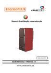
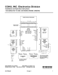
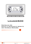
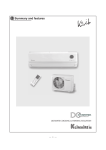
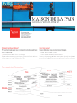
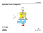
User Manual
GB
TC 110-24-A-50
VALV.
P1
P2
P3
P4
1 2 3 4 5 6 7 8 9 10 11 12
fig. 1 Aspetto esterno e schema collegamenti elettrici
Ingressi
SONDA
FLUX
POMPA
Fireplace Probe:
Temperature Range 0 – 100 °C
Consent ON/OFF:
Flowswitch/ Boiler-Sanitary thermostat
Pump:
230 Vac
VALVOLA ElectroValve:
Auxiliary:
AUX
Uscite
SERV
ElectroValve 2 wires:
Grill:
Connectors
3(N) – 4(FON)
Free Contacts
Connectors
5COM) – 6(N.C.) – 7(N.O.)
Free Contacts
Connectors
8(COM) – 9(N.C.) – 10(N.O.)
THERMOSTAT Configuration
Free Contacts
Connectors
11(N) – 12(FON)
GRILL Configuration
230 Vac:
Connectors
11(N) – 12(FON)
⇒ FUNCTIONALITY
1. ON/OFF:
The ON/OFF of the controller is through the exstended pressure of the button P4 (ON/OFF)
The state OFF is signalled with the blinking led OFF
2. ALARM Function:
If the temperature read by the PROBE is over the value Alarm thermostat A01
The acoustic and visual signal is activated
Function SILENCE: the acoustic signal could be deactivated for 5 minutes pushing a button
After this time, if the alarm condition is active, the acoustic signal starts again.
3. ANTI FREEZING Function:
If the temperature read by the PROBE is under the value of the Anti Freezing thermostat A03
The output PUMP is activated
The display shows ICE
4. STANDBY Function:
If the system is OFF
in condition of ALARM or ANTI FREEZING
The device starts ON
5. ANTI BLOCK PUMP Function:
If the PUMP is off for a time over Timer Anti block T01 (about a week)
The output PUMP is activated for T02 seconds
The display shows bLP
The function is ON also in STANDBY.
6. TEST PUMP Function:
Pushing the button P3(+)
The output PUMP is activated for the time of the button’s pushing
The display shows tSt
GB
7. SANITARY Function:
Modality H__= H0
Production of internal fireplace sanitary WITHOUT Sanitary Electro valve
In case of:
Input FLUX = ON Flowswitch contact close for Sanitary Water Request
The PUMP is deactivated
The Function is signalled with the blinking led PUMP and high hyphen on the first digit of the display
The function is NOT ACTIVE when the PROBE’s temperature is over the value of the security thermostat A02
Modality H__= H1
Production of internal sanitary or external boiler WITH Sanitary Electro Valve
In case of:
Input FLUX = ON
Flowswitch contact close for sanitary water request
Or contact boiler thermostat close for temperature not reached
The temperature read by the PROBE is over the thermostat T-VALV
The output VALV is activated for the sanitary ElectroValve management
The activation of the PUMP is forced
The function is signalled with the high segment on the display’s first digit
The Function is NOT ACTIVE when the PROBE‘s temperature is over the value security thermostat A02
Modality H__= H1b
Production of internal sanitary or external boiler WITH Sanitary Pump
In case of:
Input FLUX = ON
Flowswitch contact close for sanitary water request
Or contact boiler thermostat close for temperature not reached
The temperature read by the PROBE is over the Thermostat T-VALV
The output VALV is deactivated
The output PUMP is activated for the sanitary Pump management
The function is signalled with the high segment on the display’s first digit
The Function is NOT ACTIVE when the PROBE‘s temperature is over the value security thermostat A02
⇒ ‘SERV’ CONFIGURATION
It allows the functioning of the output SERV
Function GRILL:
button P2(-) Output= OFF
button P3(+) = ON
Function THERMOSTAT programmable
To enter the Menu push together buttons P2(-) and P3(+) for about 5 seconds
The display shows the configuration: Gri or tEr
Modify through buttons P2(-) and P3(+) together to button P4(MENU)
To exit and memorise wait about 5 seconds.
⇒ MAIN Menu
Setting out of the functioning THERMOSTAT of the controlled outputs:
T-PUMP: for the control of the PUMP functioning
T-VALV: for the control of VALVE
T-AUX: for integration of the gas boiler, ElectroValve or other application
T-SERV: for the controller of Electro Valve or other application
Through the click of the button P4(MENU) is visualised the values of the setted thermostats signalled by the
correspondent blinking led PUMP / VALV / AUX / SERV
To modify:
Chose the value to modify
Through buttons P3(+) e P2(-) increase/decrease the value
To memorise wait about 5 seconds or push button P4(MENU)
The Thermostat SERV is not available in case of configuration SERV = GRILL
See Menu ‘SERV’ CONFIGURATION
Main menu Parameters
T-PUMP thermostat
T-VALV thermostat
T-AUX thermostat
T-SERV thermostat
U.M
[°C]
[°C]
[°C]
[°C]
Code
Min
A 04
A 05
A 06
A 07
20
20
20
20
Fabbrica
Max
40
45
50
60
85
85
85
85
Valori impostati
GB
⇒ INSTALLER Menu
The admission to this Menu is only for INSTALLERS or EXPERT PERSONNEL, because modified
parameters could damage the product or could make the product not fit for the applications.
To enter the MENU push together buttons P4(MENU) and P1 (ON/OFF) for about 5 seconds.
To visualise the parameters use buttons P3(+) and P2(-)
To Visualise the parameter push button P4(MENU)
To modify the value push buttons P3(+) or P2(-) together with P4(MENU)
To see the list of the parameters and memorise push button P4(MENU)
To exit and memorise wait about 5 seconds.
INSTALLER Menu Parameters
Thermostat of activation ALARM Function
SAFETY Thermostat
ANTI-FREEZING thermostat
Thermostat T-PUMP Hysteresis
Thermostat T-VALV Hysteresis
Thermostat T-AUX Hysteresis
Thermostat T-SERV Hysteresis
Timer of Pump ANTI BLOCK
Time of activation Pump in ANTI BLOCK
ANTIFREEZING Enable
SANITARY Modality
U.m.
°C
°C
°C
°C
°C
°C
°C
h
sec
Code
Min
Default
Max
A 01
A 02
A 03
i 04
i 05
i 06
i 07
t 01
t 02
P06
H__
85
20
4
1
1
1
1
1
0
0
0
90
85
6
2
2
2
2
168
20
1
0
99
90
8
15
15
15
15
255
99
1
1b
Set Values
⇒ FAILURE SIGNALLING OR ALARMS
The controller could signal the damage of the probe.
Blinking damage messages:
Lo:
out of range to the low temperature (under 0°C):
Hi:
out of range to the high temperature (over 100°C):
Probe broken
Probe in short circuit
Power Supply: 230 Vac ±10%~ 50HZ:
Protection: Internal fuse T3,15 A
Temperature Probe:
Functioning Temperature range
Measure Range:
PUMP:
VALVE:
Outputs:
AUX:
SERV:
230 Vac
Free Contacts
Free Contacts
230 Vac
-50°C / 130 °C
0 – 99 °C: ± 1°C
5A Max
5A Max
5A Max
5A Max
Mechanical dimensions: Inbox Controller: 120 x 80 x 50 [mm]
Norme applicate: EN 60730-1 50081-1 EN 60730-1 A1 50081-2
Technical characteristics
In the view of a constant development of their products, the manufacturer reserves the right for changing
technical data and features without prior notice. The consumer is guaranteed against any lack of
conformity for 24 months from the delivery time, according to the European Directive 1999/44/EC. The
full text of guarantee is available on request from the seller.
The company does not answer for damages due to a wrong wiring or improper use of the device!
TiEmme elettronica Marsciano (PG) Italy
Tel: +39 075.8743.905 Fax: +39 075.8742.239
[email protected]
GB
DIMOSTRATION DIAGRAMS
Here are some examples of demonstrative systems and the configuration of the parameters: thermostats,
H , SERV, for the management of the Heating , Sanitary circuit and Integratio Boiler.
H 0
30 < S1 < 45 °C:
PUMP=ON e VALV= OFF
PUMP e VALV = ON
PUMP = OFF
T-PUMP
30°C
S1 > 45 °C:
T-VALV
45°C
If FLUX=Close
A02
85°C
S1 > 85 °C:
PUMP e VALV = ON
T-AUX
45°C
S1 > 45°C:
Gas Boiler Integration =OFF
30 < S1 < 45 °C:
PUMP e VALV= ON
H 1
30°C
S1 > 45 °C:
PUMP=ON e VALV = OFF
T-VALV
45°C
If FLUX=Close
VALV =ON
A02
85°C
S1 > 85 °C:
VALV =OFF
T-AUX
45°C
S1 > 45°C:
Gas Boiler Integration =OFF
30 < S1 < 45 °C:
PUMP e VALV= ON
30°C
S1 > 45 °C:
PUMP=ON e VALV = OFF
T-VALV
45°C
If FLUX=Close
VALV =ON
85°C
S1 > 85 °C:
VALV =OFF
T-AUX
45°C
S1 > 45°C:
Gas Boiler Integration =OFF
30 < S1 < 45 °C:
PUMP=ON e VALV= OFF
S1 > 45 °C:
If FLUX=Close
and S1> 30°C:
S1 > 85 °C:
PUMP=OFF e VALV=ON
PUMP=ON e VALV=OFF
S1>45°C:
Gas Boiler Integration =OFF
30 < S1 < 45 °C:
PUMP=ON e VALV= OFF
S1 > 45 °C:
If FLUX=Close
and S1> 30°C:
S1 > 85 °C:
PUMP=OFF e VALV=ON
PUMP=ON e VALV=OFF
S1 > 45°C:
Gas Boiler Integration =OFF
30°C
T-VALV
45°C
A02
T-AUX
85°C
45°C
H 1b
T-PUMP
30°C
T-VALV
45°C
A02
T-AUX
85°C
45°C
VALV
POMPA
Internal Sanitary with circulation / Valve management
F
N
VALV
POMPA
Sanitary with external exchanger / Valve management
F
N
VALV
A02
T-PUMP
F
N
1 2 3 4 5 6 7 8 9 10 11 12
T-PUMP
H 1b
1 2 3 4 5 6 7 8 9 10 11 12
1 2 3 4 5 6 7 8 9 10 11 12
T-PUMP
H 1
Internal Sanitary with PUMP Stop
PUMP e VALV =ON
POMPA
Sanitary with external exchanger / Pump management
1 2 3 4 5 6 7 8 9 10 11 12
F
N
VALV
POMPA
Internal Sanitary with circulation / Pump management
1 2 3 4 5 6 7 8 9 10 11 12
PUMP and VALV =ON
F
N
VALV
POMPA