1
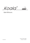
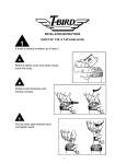
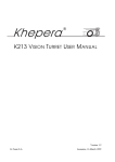
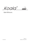
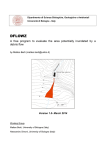
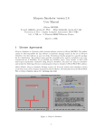
Khepera
¨
K2D VIDEO TURRET USER MANUAL
Version 1.1
K-Team S.A.
Lausanne, 10 March 1999
Documentation author
K-Team S.A.
Ch. du Vuasset
CP 111
1028 Préverenges
Switzerland
Trademark Acknowledgements
Khepera: K-Team S.A.
NOTICE:
• The contents of this manual are subject to change without notice.
• All efforts have been made to ensure the accuracy of the contents of this manual. However, should any errors be detected. In this case, please inform K-Team S.A..
• The above notwithstanding K-Team S.A. can assume no responsibility for any errors
in this manual.
TABLE OF CONTENT
Introduction . . . . . . . . . . . . . . . . . . . . . . . . . . . . . . . . . . . . . . . . . 1
How to Use this Manual . . . . . . . . . . . . . . . . . . . . . . . . . . . 1
Safety Precautions . . . . . . . . . . . . . . . . . . . . . . . . . . . . . . . . . . . . 1
Unpacking and Inspection . . . . . . . . . . . . . . . . . . . . . . . . . . . . . . 1
The K2D video turret . . . . . . . . . . . . . . . . . . . . . . . . . . . . . . . . . 2
Overview of the turret . . . . . . . . . . . . . . . . . . . . . . . . . . . . 2
Serial/video connection module . . . . . . . . . . . . . . . . . . . . . 2
K2D cable unroller . . . . . . . . . . . . . . . . . . . . . . . . . . . . . . . 3
Video camera specifications . . . . . . . . . . . . . . . . . . . . . . . 4
Connections . . . . . . . . . . . . . . . . . . . . . . . . . . . . . . . . . . . . . . . . . 4
Assembling . . . . . . . . . . . . . . . . . . . . . . . . . . . . . . . . . . . . 4
Disassembling . . . . . . . . . . . . . . . . . . . . . . . . . . . . . . . . . . 5
Complete installation . . . . . . . . . . . . . . . . . . . . . . . . . . . . . 6
References . . . . . . . . . . . . . . . . . . . . . . . . . . . . . . . . . . . . . . . . . . 6
1
INTRODUCTION
The hardware of Khepera is based on a modular concept. The K2D video turret is a
module that can be plugged on the top of a Khepera robot making video acquisition possible. Due to the configuration and the geometric shape of this turret, no additional turrets can be plugged on the top of it. This kind of turret is called a “top turret”.
The K2D video turret is a passive device without on-board processing. A video signal is delivered via a wired link to a fixed installation. At this level the video signal can
be used by custom equipment not included in this package.
1.1
How to Use this Manual
This manual is organised into four chapters. To learn how to make the best use of
your K2D video turret you are urged to read all of chapters 1 through 4 (very short...!)
Chapter 1 gives you a general introduction.
Chapter 2 describes some important warnings.
Chapter 3 explains the contents of the package.
Chapter 4 gives an overview on the K2D video turret and the video/serial
connection module.
Chapter 5 explains how to connect the K2D video turret to the robot and to
the host computer and video equipment.
2
SAFETY PRECAUTIONS
Don't plug or unplug any connector or turret when the system is switched ON. All
connections and turret insertions must be made when the robot and the interface are
switched OFF. Otherwise damages can occur.
Switch OFF the robot if you will not use it for more than a day. Disconnect the power
supply removing it from the wall socket.
3
UNPACKING AND INSPECTION
Please check that you have a complete package. You should find:
• Documentation.
• The K2D video turret.
• The video/serial connection module.
• The video/serial cable and the rotating contact device.
• A power supply.
1
4
THE K2D VIDEO TURRET
4.1
Overview of the turret
Top view
Side view
1
2
Figure 1: Overview of the turret layout.
Make an external inspection of the turret. Note the location of the following parts:
1. Video camera.
2. Serial/video connector.
4.2
Serial/video connection module
The serial/video connection module has several functionalities:
• It power supply both the Khepera robot and the camera.
• It makes a standard RS232 serial link available.
• It performs the signal processing to make a standard video signal available.
1 2 3 4 5 6 7
Figure 2: Layout of the serial/video connection module.
2
Please note the location of the following parts:
1. RS232 standard connector, for link to the host computer.
2. Green LED indicating the activity of the RS232 serial link for datas going
from the robot to the host computer.
3. Red LED indicating the activity of the RS232 serial link for datas going
from the host computer to the robot .
4. Minidin connection to the robot.
5. Power indicator.
6. Video output.
7. Power supply.
IMPORTANT WARNING: to power this module please use only the power
supply that has been delivered in the K2D package. This power supply is stronger
than the standard Khepera one. If you use the standard Khepera power supply you
can damage it! On the contrary you can use the K2D power supply for the normal
Khepera interface and charger module.
4.3
K2D cable unroller
The cable unroller gives to the robot more motion freedom. The general layout of
this devide is the following:
1 2 3 4
Figure 3: K2D cable unroller layout.
Please note the location of the following parts:
1. Connector to be plugged on the K2D video module (point 2 of figure 1).
2. Flexible cable.
3. Connector to the serial/video interface.
4. Mechanical attachements.
3
4.4
Video camera specifications
The camera specifications depend from the model of K2D video module you have:
Model
K2D-B/W-PAL
Image sensor
500(H) x 582(V)
CCIR
K2D-C-NTSC
510(H) x 492(V)
PAL
Scanning system
Scanning frequency
K2D-B/WNTSC
Inter-line type 1/3” CCD solid state image sensor
Effective picture element
TV system
K2D-C-PAL
EIA
NTSC
2:1 interlace
Horizontal 15.625 KHz ± 1%
Vertical
50 Hz ± 1%
Synchronization system
Horizontal 15.734 KHz ± 1%
Vertical
60 Hz ± 1%
Internal
Horizontal resolution
380TV-lines or
greater
330TV-lines or
greater
380TV-lines or
greater
330TV-lines or
greater
Min. illuminance
of object
5.0 lux (at 50%
signal level)
2.5 lux (at 50%
signal level)
5.0 lux (at 50%
signal level)
2.5 lux (at 50%
signal level)
> 45 dB
~ 48 dB
> 45 dB
~ 48 dB
1/60 ~
1/100’000 s
1/60 ~
1/30’000 s
S/N ratio
γ=0.45
Gamma characteristics
AGC
ON
IRIS control
1/50 ~
1/100’000 s
White balance
1/50 ~
1/30’000 s
ATW: 2600° K ~ 9000° K
-
Standard lens
2.5 mm
4 mm
2.5 mm
4 mm
Optional lens
3.6 / 8 / 16 mm
5.6 / 8 / 16 mm
3.6 / 8 / 16 mm
5.6 / 8 / 16 mm
5
CONNECTIONS
The assembling and disassembling of additional turrets is a delicate operation. Try to
avoid as much as possible this manipulation and perform it carefully. Please follow the
indication of this manual to avoid damages to your modules. The K-Team can assume no
responsibility for any damage caused by wrong manipulations.
4
5.1
Assembling
The assembling is the easier operation, but it is also necessary to perform it carefully:
• First of all choose the parameters of the module on which you plug the
new turret (the running mode that you will use on tha basic Khepera configuration, for instance) and set the jumpers if necessary. When the turrets is
assembled, it is impossible to access to the modules that are inside the
robot without disassembling it.
• Assemble the turret with the basic configuration in two steps: In a first step
place the module on the extension connector checking that all pins are on
the correct place. In a second step apply a force to insert the additional turrets into the extension connector.
• If you want to connect the robot to your workstation, use the serial connector of the turret placed on the top.
• Operate as normal.
5.2
Disassembling
This is the most difficult operation for people that are not suited to work with this kind of
hardware.
• First of all switch OFF the robot or disconnect the power supply.
• Separate the turret to the rest of the robot. To do this operation without
damages to the connections, the turret must be disconnected carefully and
all connections have to be disconnected together. This can be made using a
big plastic screwdriver and operating between the boards of the several
modules. Be careful to do not force on delicate elements, like the pins of
the circuits. Open some millimetres right, then left, then right.... and be
very careful!
Figure 4: How to disassemble an additional turret.
5
5.3
Complete installation
The complete interconnection of all devices (including the host computer, a monitor and a Khepera robot not included in this package) has to be done following the indications of figure 5. In this figure the video equipment has been simplified to a monitor,
but depends on the needs of the user.
Video
Monitor
RS232
Host computer
Figure 5: Interconnections for a full installation.
IMPORTANT WARNING:
For this installation please use only the power supply that has been delivered
in the K2D video package. This power supply is stronger than the standard Khepera one. If you use the standard Khepera power supply you can damage it!
On the contrary you can use the K2D power supply for the normal Khepera interface and charger module.
6
6
REFERENCES
[Mondada93b] Mondada F., Franzi E. and Ienne P., "Mobile robot miniaturisation: a tool
for investigation in control algorithms.", ISER3, Kyoto, Japan, 1993.
[K-Team94] Khepera User Manual 3.0, K-Team manuals, Lausanne, 1994.
7
PERSONAL ANNOTATIONS
8