1
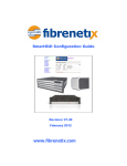
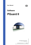
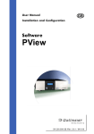
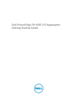
Hardware Guide
E8 Series Storage Enclosure
Revision 0.90
February, 2012
www.fibrenetix.com
E 8 series Hardware Guide
Limitations of Warranty and Liability
Fibrenetix has tested the hardware described in this User Guide and reviewed its contents.
In no event will Fibrenetix, or its distributors, be liable for direct, indirect, incidental, or
consequential damage resulting from any defect in the hardware or User Guide, even if
they have been advised of the possibility of such damages. In particular, they shall have no
liability for any program or data stored in or used with Fibrenetix products, including the
costs of recovering or reproducing these programs or data.
During the specified warranty period, Fibrenetix guarantees that the product will perform
according to specifications determined by the manufacturer, and will be free of defects.
Parts and labor of the received product, and replacement parts and labor are guaranteed
during the specified warranty period. The warranty covers defects encountered in normal
use of the product, and does not apply when damage occurs due to improper use,
abuse, mishandling, accident, sand, dirt, excessive dust, water damage or unauthorized
service. The product must be packed in its original packing material when shipped, or the
warranty will be void. In all cases, proof of purchase must be presented when a
warranty claim is being made.
Fibrenetix operates a Return to Factory warranty. The period of this warranty is three (3)
years. Warranty registration for your Fibrenetix E8 Series should be completed
electronically via the web. Please register for the Return to Factory warranty at
www.fibrenetix.com.
Technical Support Policy
If you have a problem installing your system or suspect it is malfunctioning, please
contact Fibrenetix Support via email: [email protected], or register your
support issue via our website: www.fibrenetix.com. Please have the model, serial
number, date of purchase and the distributor/reseller’s name available, as you will need to
provide this information to our support team.
Return of Product
If a distributor or Fibrenetix deems it necessary for a system to be returned for testing or
servicing, a Return Materials Authorization (RMA) number will be issued. The RMA
number must be placed on the outside of the carton in large, visible letters near the address
label. Return the complete system including all cables and software. The system must be
packed in the original packing materials and shipped prepaid. Fibrenetix will repair the
system and return it prepaid by similar common carrier and priority. Please record the
RMA number and make reference to it when enquiring on the status of the system.
E 8 series Hardware Guide
Table of Contents
Chapter 1 – Introduction ........................................................................................................... 1
Features and Benefits ................................................................................................................. 1
Understanding RAID ................................................................................................................. 1
RAID 0 ...................................................................................................................................... 2
RAID 1 ...................................................................................................................................... 2
RAID 0+1.................................................................................................................................. 3
RAID 3 ...................................................................................................................................... 3
RAID 5 ...................................................................................................................................... 4
RAID 6 ...................................................................................................................................... 4
Chapter 2 – Initial Setup and Installation .................................................................................. 5
Safety Statements ....................................................................................................................... 5
Unpacking ................................................................................................................................. 5
Environmental Considerations ................................................................................................... 5
Temperature .............................................................................................................................. 6
Air Flow .................................................................................................................................... 6
Electrical Considerations ........................................................................................................... 6
Installing a Disk Drive ............................................................................................................... 6
Locating Components ................................................................................................................ 7
FRU removal ............................................................................................................................. 8
Power and Cooling (PAC) ......................................................................................................... 8
RAID Controller ........................................................................................................................ 8
LCD Panel ................................................................................................................................. 8
Drive Carrier ............................................................................................................................. 8
Chapter 3 – Initial Configuration ............................................................................................ 10
Attaching the Fibre Channel Cables to Fibre Channel enclosures ............................................ 10
Attaching the SAS Channel Cables to a JBOD enclosure ........................................................ 10
Power sequencing of subsystems .............................................................................................. 11
Power up ................................................................................................................................. 11
Power down............................................................................................................................. 11
Accessing the RAID Controller ............................................................................................... 11
VT100 terminal (via serial port) .............................................................................................. 11
RAID subsystem RS-232C Port Configuration ....................................................................... 11
Web browser-based RAID manager ........................................................................................ 12
Web browser-based RAID manager via HTTP Proxy ............................................................. 13
Front Panel Operation ............................................................................................................. 15
Front Panel removal and insertion........................................................................................... 15
Appendix A ............................................................................................................................. 16
Troubleshooting ...................................................................................................................... 16
Appendix B ............................................................................................................................. 17
Technical Specifications ......................................................................................................... 17
E 8 series Hardware Guide
Figures
Figure 1 RAID 0 configuration ................................................................................................ 2
Figure 2 RAID 1 configuration ................................................................................................ 2
Figure 3 RAID 0+1 configuration............................................................................................ 3
Figure 4 RAID 3 configuration ................................................................................................ 3
Figure 5 RAID5 configuration ................................................................................................. 4
Figure 6 RAID6 configuration ................................................................................................. 4
Figure 7 Front view of enclosure ............................................................................................. 7
Figure 8 Rear view of E88 12 bay dual RAID enclosure ......................................................... 7
Figure 9 Rear view of E8 16 bay JBOD enclosure .................................................................. 8
Figure 10 Drive mounting ........................................................................................................ 9
Figure 11 Upgrading/replacing memory .................................................................................. 9
Figure 12 Rear view of JBOD I/O module ............................................................................ 10
Figure 13 Daisy chaining JBOD enclosures .......................................................................... 10
Figure 14 Serial Port Menu .................................................................................................... 12
Figure 15 GUI Configuration Screen ..................................................................................... 14
E 8 series Hardware Guide
Preface
This User Guide describes the installation, configuration and operation of the following
products:
• E8-1264-F281, 12 drive bay, single controller RAID subsystem with quad 8 gigabit
Fibre Channel interfaces (total 4 x 8gigabit F/C ports)
• E88-1264-F281, 12 drive bay dual controller RAID subsystem with quad 8 gigabit Fibre
Channel interfaces per RAID controller (total 8 x 8gigabit F/C ports)
• E8-1664-F281, 16 drive bay, single controller RAID subsystem with quad 8 gigabit
Fibre Channel interfaces (total 4 x 8gigabit F/C ports)
• E88-1664-F281, 16 drive bay dual controller RAID subsystem with quad 8 gigabit Fibre
Channel interfaces per RAID controller (total 8 x 8gigabit F/C ports)
• E8-1262-J31 JBOD Expansion enclosure.
• E88-1262-J31 JBOD Expansion enclosure.
• E8-1662-J31 JBOD Expansion enclosure.
• E88-1662-J31 JBOD Expansion enclosure
The E8 is the latest member of a family of high performance Fibre Channel to
SAS/SATA systems. The dual system (E88 models) uses Serial Attached SCSI (SAS) disk
drives only and the single controller (E8 models) can use SAS or SATA drives. In addition
the system supports a JBOD expansion unit (E8-1262-J31) via wide (4 lane) 6 gigabit SAS
ports for future use.
Audience
This User Guide is intended for use by the person installing and/or operating the E8
storage enclosure. For details about the host system, refer to the documentation supplied
with the host system.
Related Documentation
• SmartGUI User Guide
Conventions Used In This User Guide
The following conventions are used throughout this User Guide.
A WARNING means beware. There is a risk of electric shock or
personal injury. Before working on the enclosure, be aware of the
hazards that exist.
A CAUTION means take care. There is a risk of causing damage to
the equipment or of losing data.
A NOTE gives general information, such as helpful tips and
references to related information.
E 8 series Hardware Guide
Chapter 1 – Introduction
Thank you for purchasing your Fibrenetix E8 Series RAID enclosure. Designed for speed,
reliability, compatibility and performance, the E8 enclosure is easy to install, providing an
outstanding and versatile solution to meet all your data storage requirements. The User
Guide presumes that you are familiar with standard computer operations including
managing and organizing files and folders. If you are unfamiliar with these operations,
please consult your computers User Guide.
Features and Benefits
The Fibrenetix E8 series of RAID enclosures offers an extremely versatile, high capacity
solution, perfect for any End-User environment where high performance, problem free
mass storage is required, including:
• Backup storage.
• Direct Attached Storage – High-speed local storage device for dedicated
workstations.
• Server Attached Storage – High-speed storage device attached to your server.
Features include:
• Single or dual controller models
• RAID levels 0, 1, 0+1, 3, 5, 6, 30, 50, 60 or JBOD
• RAID set migration
• Four 8Gbit Fibre Channel ports per controller
• High performance 6 gigabit SAS expansion channels
• Up to 112 SAS hot-swap hard drives.
• Up to 32 physical drives per individual RAID set
• Up to 4 GB controller cache
• Dual Power and Cooling (PAC) Modules
• Removable push button LCD panel for easy setup and configuration (16 bay only)
• WEB based RAID management via onboard Ethernet
• Variable speed fans
• O/S independent and transparent
• Optimized for high performance, high capacity applications
Understanding RAID
RAID is an acronym for Redundant Array of Independent Disks. A RAID system consists
of an array of multiple independent hard disk drives that provide high performance and
fault tolerance. The RAID controller implements several levels of the Berkeley RAID
technology. An appropriate RAID level is selected when the volume sets are defined or
created. This decision is based on disk capacity, data availability (fault tolerance or
redundancy) and disk performance.
The RAID controller makes the RAID implementation and the disks physical configuration
transparent to the host operating system. This means that the host operating system drivers
and software utilities are not affected, regardless of the RAID level selected. Correct
installation of the disk array and the controller requires a proper understanding of RAID
technology and the concepts.
Page 1
E 8 series Hardware Guide
RAID 0
RAID 0, also referred to as striping, writes stripes of data across multiple disk drives.
RAID 0 does not provide any data redundancy, but does offer the best high-speed data
throughput. RAID 0 breaks up data into smaller blocks and then writes a block to each
drive in the array. Disk striping enhances performance because multiple drives are
accessed simultaneously; but the reliability of RAID Level 0 is less than any of its member
disk drives due to its lack of redundancy.
Figure 1 RAID 0 configuration
RAID 1
Figure 2 RAID 1 configuration
RAID 1 also known as “disk mirroring”, means that data written to one disk drive is
simultaneously written to a second disk drive. Read performance may be enhanced if the
array controller can simultaneously access both members of a mirrored pair. During writes,
there will however, be a minor performance penalty when compared to writing to a single
disk as two writes must occur (one to each disk drive). If one drive fails, all data (and
software applications) is preserved on the other drive. RAID 1 offers extremely high data
reliability, but at the cost of doubling the required data storage capacity.
Page 2
E 8 series Hardware Guide
RAID 0+1
Figure 3 RAID 0+1 configuration
RAID 0+1 is a combination of RAID 0 and RAID 1, combining striping with disk
mirroring. RAID Level 0+1 combines the fast performance of Level 0 with the data
redundancy of Level 1. In this configuration, data is distributed across several disk drives,
similar to Level 0, which are then duplicated to another set of drives for data protection.
RAID 3
Figure 4 RAID 3 configuration
RAID 3 provides disk striping and data redundancy though the use of a dedicated parity
drive. RAID 3 breaks up data into smaller blocks, calculates parity by performing an
exclusive-or operation on the blocks, and then writes the blocks to all but one drive in the
array. The parity data created during the exclusive-or operation is then written to the
remaining drive in the array. If a drive fails, data on the failed drive can be recovered using
the information on the parity drive. RAID 3 is a good choice for applications that require
very fast data transfer rates or large data transfers.
Page 3
E 8 series Hardware Guide
RAID 5
In RAID5, the parity information is written to all of the drives in the array rather than
being concentrated on a dedicated parity disk. If one drive in the array fails, the parity
information can be used to reconstruct the missing data from that drive. All drives in the
array can read and write data at the same time, greatly increasing the performance of the
RAID system.
Figure 5 RAID5 configuration
RAID 6
RAID 6 extends a RAID 5 array by using dual distributed parity. Data and parity is striped
at block level across all member drives, just like in RAID 5. However, two sets of parity
are calculated and written across all the drives. When a disk fails, the data is recovered
from the remaining disks. RAID 6 provides the ultimate level of fault tolerance and can
sustain two simultaneous drive failures without downtime or data loss. RAID 6 offers a
good solution for mission-critical data.
Figure 6 RAID6 configuration
RAID levels 30, 50 and 60 are used to combine multiple RAID sets together to appear as a
single volume.
Page 4
E 8 series Hardware Guide
Chapter 2 – Initial Setup and Installation
This Chapter describes the installation and set up of the E8 storage enclosure. Important
safety details are described along with the environmental and electrical precautions that
must be taken. The location of components within the enclosure is also shown.
Please read this chapter carefully before attempting to install
or operate the E8 enclosure.
Safety Statements
The following safety requirements must be understood before you install or operate the
system.
Warning: Disconnect all power supply inlets before opening the
E8 series storage enclosure for maintenance.
Caution: Do not place the enclosure on an uneven or unstable work
surface.
Caution: Do not place or drop objects onto the enclosure and do
not force any foreign objects into it.
Caution: Do not expose the E8 series storage enclosures to
extreme temperatures (below 5 ºC or above 40 ºC) or to direct
sunlight.
Caution: Allow disk drives and power supplies to reach
ambient
room
temperature before applying power to the
enclosure.
Unpacking
When you receive the system, visually inspect the exterior of the packaging for any signs of
damage. If any damage is found, you should inform your distributor. Once the packaging is
opened, the contents should be checked against the enclosed Packing List. If any items are
missing or damaged you should contact your distributor immediately.
Environmental Considerations
This section outlines the environmental factors that must be considered when choosing a
suitable location to install the storage enclosure.
Page 5
E 8 series Hardware Guide
Temperature
The operating temperature of the storage enclosure is between 5oC and 40oC. However, it is
not recommended that the enclosure be continuously run at these extreme temperatures.
Consideration should therefore be give to ensure that the room ambient temperature is
compatible with these specifications.
Air Flow
To ensure that internal heat built up is properly dissipated into the surrounding
environment, the enclosure should be positioned such that no air vents are blocked or
obstructed in any way. Failure to ensure this can lead to heat build up in the enclosure and
damage to the components.
Electrical Considerations
You must ensure that the required current does not exceed the rating of the power source.
This includes cabling, power distribution units, filters and any other devices through which
the main current flows. Surge currents must be catered for. Disk drives may consume twice
the amount of current at start-up time as they do during steady state operation.
Installing a Disk Drive
Warning: Disconnect the power supply inlets before opening the
storage enclosure for maintenance.
Caution: Do not place or drop objects onto the enclosure and do
not force any foreign objects into it.
To install a Disk Drive caddy in the storage enclosure, follow the procedure below:
1. Orient the caddy so that the LED indicator is at the left hand side.
2. With the locking lever fully open, gently slide the caddy into the desired slot on the
front of the enclosure.
3. When the caddy is in all the way, slowly close the locking lever until it clicks into
place.
Page 6
E 8 series Hardware Guide
Locating Components
The following picture of the E88-1664-F281 shows where the components are located
within the enclosures.
Front Panel Display
Drive Caddies
Figure 7 Front view of enclosure
The above drawing shows the front view of the enclosure. The LCD panel is designed to
be removable (16 bay model only). This is important in many high end applications
where security is an important consideration. It also facilitates serviceability as many
other vendors do not provide an easy method of replacing this unit.
Note: The JBOD enclosure does not feature an LCD panel.
The picture bel ow s hows t he E88-1264-F281, the dual PAC modules are shown at
the left and right side of the chassis with the RAID controllers in the middle section. The
port designations are shown below and the 16 bay system has a similar arrangement.
Configuration is achieved either by the RS-232 terminal configuration port or through the
LAN interface. The debug port is for engineering use only. The Fibre Channel host ports are
designated channel 0 through 3 as viewed from left to right.
Figure 8 Rear view of E88 12 bay dual RAID enclosure
Page 7
E 8 series Hardware Guide
Figure 9 Rear view of E8 16 bay JBOD enclosure
FRU removal
Power and Cooling (PAC)
The PAC modules can be easily removed by unscrewing the thumbscrews and pulling it
outwards.
RAID Controller
To gain access to the RAID controller unscrew the thumbscrews in an anti-clockwise
direction, lower the latch assembly and pull the controller outwards.
LCD Panel
The LCD panel (16 bay onl y) is removed by depressing the button on the right hand
side of the panel assembly and swinging outwards whilst pulling the panel towards you.
Replace by inserting the retaining hook on the left hand side of the panel into the receiver
and ensuring that the pins are correctly mated gently push inwards.
Drive Carrier
The drives are mounted in purpose designed caddies. The caddies are designed for hot swap
operation with a damping handle and EMI shielding. Status information is conveyed via a
light pipe. Removal of the drive carrier is achieved by pressing on the upper part of the
handle on the right hand side above.
Page 8
E 8 series Hardware Guide
Figure 10 Drive mounting
The drives are mounted from the underside of the drive caddy by the four screws shown
above.
Upgrading the memory
The memory installed in the RAID controller module can be upgraded by removing the
controller as described above and removing the memory by opening the securing clips.
Insert the new memory in its place by orienting the memory correctly and firmly
inserting it into the socket. When the memory is correctly inserted, the securing clips
should snap into place.
Figure 11 Upgrading/replacing memory
Page 9
E 8 series Hardware Guide
Chapter 3 – Initial Configuration
This Chapter describes how to install the hardware and how to connect to and access the
RAID controller.
Note: A maximum of 32 physical drives is allowed per RAID set.
Attaching the Fibre Channel Cables to Fibre Channel enclosures
There are four Fibre channel SFP Ports on the rear of the enclosure at the rear of the unit.
Insert the SFP adapters and then attach the FC cabling to these ports. Ensure that the HBA
drivers are loaded correctly.
Attaching the SAS Channel Cables to a JBOD enclosure
The SAS JBOD cable is supplied with the JBOD expansion enclosure and connects from a
SAS expansion port of the E8 (shown in Figure 13) to the Exp. in port of the JBOD shown
in Figure 12. The connector type is mini-SAS.
Figure 12 Rear view of JBOD I/O module
A maximum of 7 enclosures (1X16 bay RAID chassis + 6X16 bay JBODs) can be
connected with a total of 112 devices. The following diagram shows the recommended
method for adding additional JBOD enclosures.
Figure 13 Daisy chaining JBOD enclosures
E8 RAID Enclosure
SAS Daisy Chain 1
SAS Daisy Chain 2
JBOD 1
JBOD 4
JBOD 2
JBOD 5
JBOD 3
JBOD 6
Maximum of 112 devices using 6 x 16 bay JBODs and 1 x RAID enclosu
Page 10
E 8 series Hardware Guide
Note: When adding JBOD enclosures follow the order shown in
Figure 13 above.
Power sequencing of subsystems
Power up
1. Apply power to JBOD enclosures
2. Wait one minute to allow drives to come up to speed
3. Power up RAID enclosure
Power down
1.
2.
3.
4.
Halt host I/O activity
Allow time for RAID controller cache to flush
Power down the RAID enclosure
Power down the JBODs
Accessing the RAID Controller
Following the hardware installation, the RAID subsystem disk drives must be configured
and the volume sets initialized, before they are ready to use. This is carried out using one
of the following methods:
• VT100 terminal connected through the RAID subsystem serial port.
• Firmware-embedded TCP/IP & web browser-based RAID manager via the
10/100 Ethernet LAN port.
The embedded RAID manager provides complete control and management of the RAID
subsystem, eliminating the need for additional hardware or software.
NOTE: The RAID subsystem must only be accessed through one
method at a time.
VT100 terminal (via serial port)
The serial port located at the rear of the unit can be used in VT100 mode. The interface
cable provided connects the RS232 port to a PC. The embedded RAID management
interface can access the array through the RS-232 port. You can attach a VT-100
compatible terminal or a PC running a VT-100 terminal emulation program to the serial
port to access the text-based Set-up Menu. The default password is “0000” (without
quotes).
RAID subsystem RS-232C Port Configuration
To ensure proper communications between the RAID subsystem and VT-100 Terminal
Emulation program, use the following communication settings:
Connection
Baud Rate
Data bits
Stop
Flow Control
Page 11
Null-modem cable
115,200
8
1
None
E 8 series Hardware Guide
By connecting a VT100 terminal, or a PC operating in an equivalent terminal emulation
mode, all RAID subsystem monitoring, configuration and administration functions can be
carried out.
There are a wide variety of Terminal Emulation packages available, such as
Hyperterm. Open the Terminal Emulator of your choice , and configure the Settings of
the Terminal port as shown in the Terminal Requirements table above.
When the VT100 Terminal set-up is complete, you can press the " X " key (on your
Terminal) to link the RAID subsystem and Terminal together. The disk array Monitor
Utility screen is displayed on your VT100 Terminal.
Figure 14 Serial Port Menu
Please refer to the SmartGUI User Guide to continue with the configuration of the
enclosure using the VT-100 terminal software.
Web browser-based RAID manager
The Firmware-embedded web browser RAID manager is a HTTP–based application,
which utilizes the browser installed on your operating system. You can use the Ethernet
LAN port (see Chapter 2 for location of components) to configure the subsystem without
any additional software or drivers.
It is possible to manage the RAID subsystem remotely without adding any user specific
software (platform independent) via standard web browsers connected directly to the
10/100 Ethernet RJ45 LAN port.
Page 12
E 8 series Hardware Guide
To configure the RAID subsystem on a local or remote machine, you need to know its IP
Address. The default IP address is detailed on the Product Documentation and Quality
Sheet provided with the unit and is shown on the front panel display when the system is
powered up. To launch the TCP/IP & Web Browser-based RAID Manager enter:
http://[IP Address]
NOTE: You must be logged-in as administrator with local
admin rights on the workstation to remotely configure RAID
subsystem. The user name and password are case sensitive. The
default values are:
User Name: “admin”
Password:
“0000”
Note: The default IP address can be changed through the front
panel prior to GUI operation. See page 15 for a description of front
panel operation.
Web browser-based RAID manager via HTTP Proxy
The browser based RAID manager can be accessed via a HTTP Proxy. The Fibrenetix
system comes with proxy software for Windows based host systems. To run the proxy
software, double click on the executing file archttp.exe. The Archttp dialog box
appears. This allows a HTTP session to be established via the serial port. Connect the
supplied serial cable to an unused com port on the server and enter the com port number in
the dialog shown in the diagram below.
The Parameters for the General Setting are:
• TCP Port value = 1 ~ 65535.
• RAID Connected to value = 1 ~ 10 where 1 is for COM1, 2 for COM2 and so on...
• BaudRate value = {2400, 4800, 9600, 19200, 38400, 57600, 115200}
NOTE: The RAID controller default baud rate is 115200.
When the program starts running, the following window appears:
Page 13
E 8 series Hardware Guide
To start the ArcHttpProxy Server web-browser management, click Start.
Type the User Name and Password when prompted. The RAID controller default User
Name is "admin" and the Password is "0000". After entering the user name and password,
press Enter to start-up the Http Proxy Server. The RAID Management software is now
accessible as shown below:
Figure 15 GUI Configuration Screen
Page 14
E 8 series Hardware Guide
NOTE: Alert by Email Configuration can only be set in the webbased configuration
Front Panel Operation
The system ( 1 6 b a y o n l y) can also be configured from the front panel display. It is
recommended that detailed configuration is performed using normal keyboard or mouse
input rather than through the front panel, however the display is useful for setting up IP
addresses prior to more involved configuration and reading status information. Interaction
with the keypad is achieved by using the four buttons shown in the following diagram:
The four buttons are designated as follows:
• esc – Backs up a level
• ent – Selects a menu option
• ↓ - Moves forward to next field
• ↑ - Moves backward to next field
The default password is “0000” which may be entered through the panel.
Front Panel removal and insertion
Removal
• Depress and hold the Front Panel removal button, which is mounted on the right
hand side or the front panel.
• Gently swing the right hand side of the Front Panel away from the main chassis.
• Move the Front Panel slightly to the right and remove.
Insertion
• Slip the left hand side of the Front Panel into its mounting hole on the main
chassis.
• Depress and hold the Front Panel removal button.
• Gently swing the right hand side of the Front Panel towards the main chassis until
there is contact between the Front Panel and the main Chassis.
• Holding the Front Panel in Place release the Removal button.
• Now push the ESC button on the Front Panel to reactivate it.
Refer to the SmartGUI manual for further information on configuration.
Page 15
E 8 series Hardware Guide
Appendix A
Troubleshooting
Q. I have created a 2.5 TB LUN and my Operating System does not recognize the full
capacity.
A. Ensure that your Operating System supports volumes sizes greater than 2 TB. This is
achieved by using 16 bit SCSI Command Descriptor Blocks. If the Operating System does
not support this (versions of Windows prior to WIN2K3 Service Pack 1) then you have the
ability to use 4K block sizes rather than 512 bytes to overcome this limitation. Note that
dynamic disk support is not available when using non standard block sizes.
These options are presented to the user when volumes greater than 2TB are initially
configured.
Q. My Operating system does not recognize the newly created volume.
A. Verify that the HBA drivers are correctly loaded, if the HBA supports BIOS
recognition, check to see if the volume is recognized at the BIOS level. Ensure that the
volume is correctly mapped to the appropriate host channel (refer to the SmartGUI user
manual for information on volume mapping).
Q. My Fibre Channel system is not operating correctly at 8 gigabit speeds.
A. Hard set the E8 for 8Gb operation and Loop Topology. Refer to the SmartGUI user manual
for information on setting the FC host speed.
Q. I have created a volume set and my Operating system does not “see” the device.
A. Verify that the volume is mapped to the appropriate channel, by default volumes are
mapped to channel 0. Ensure that the Host Bus Adapter device drivers are correctly loaded.
A-1
E 8 series Hardware Guide
Appendix B
Technical Specifications
System
Max number of devices:
Max number of disk drives per
RAID set:
Maximum number of drives per
enclosure
Supported RAID levels:
Host Bus Interface:
Maximum controller cache
System setup and mgmt:
System Alarms/Alerts:
Power supplies and Cooling
112
32
12/16
JBOD, 0, 1, 0+1, 3, 5, 6, 30, 50, 60
Quad 8GBit Fibre Channel
4 GB
RS-232, telnet, Web-browser and SNMP
Audible alarm, LEDs, RS-232,Web-browser, Email and SNMP
traps
Combined redundant power and cooling Modules.
Physical Dimensions
Height:
Width:
Depth:
Weight:
3 U 13.35cm (5.25 inches)
48.25cm (19 inches)
52.07cm (20.5 Inches)
TBA
Power Supply
AC Input Voltage:
Input Frequency:
Peak output Power:
100V-240V
50-60Hz
TBA
Temperature
Operating Temperature:
Non-operating Temperature:
Maximum rate of Temperature
change
5°C to 40°C
-40°C to +65°C
20°C per hour
Humidity
Relative operating humidity:
Non-operating humidity:
10% to 80%, non-condensing
10% to 95%, non-condensing
Altitude
Operating Altitude
Non-operating Altitude:
-61m to 3,048m (-200ft. to 10,000ft)
-61m to 12,000m (-200ft. to 39,370ft)