1
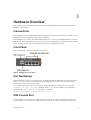
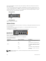
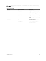
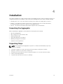
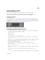
Dell PowerEdge FN 410S I/O Aggregator
Getting Started Guide
Notes, Cautions, and Warnings
NOTE: A NOTE indicates important information that helps you make better use of your computer.
CAUTION: A CAUTION indicates either potential damage to hardware or loss of data and tells you
how to avoid the problem.
WARNING: A WARNING indicates a potential for property damage, personal injury, or death.
Copyright © 2014 Dell Inc. All rights reserved. This product is protected by U.S. and international copyright and
intellectual property laws. Dell™ and the Dell logo are trademarks of Dell Inc. in the United States and/or other
jurisdictions. All other marks and names mentioned herein may be trademarks of their respective companies.
2014 - 03
Rev. A00
Contents
1 About this Guide........................................................................................................ 5
2 Introduction............................................................................................................... 7
Product Description...............................................................................................................................7
3 Hardware Overview..................................................................................................9
Internal Ports......................................................................................................................................... 9
Front Panel.............................................................................................................................................9
Port Numbering.....................................................................................................................................9
USB Console Port..................................................................................................................................9
System Status.......................................................................................................................................10
4 Installation................................................................................................................ 13
Unpacking the Aggregator.................................................................................................................. 13
Unpacking Steps.................................................................................................................................. 13
5 Installing and Configuring the Aggregator...................................................... 15
Installing a switch in a Dell PowerEdge FX2 Server Chassis.............................................................. 16
Connecting a Console Terminal.........................................................................................................16
Invoking the X-Loader and U-Boot CLIs............................................................................................ 17
Reconfiguring Default Settings........................................................................................................... 17
Before You Start............................................................................................................................. 17
Reconfiguration Using the CMC Interface................................................................................... 18
Reconfiguration Using the CLI......................................................................................................18
Aggregator Auto-Configuration......................................................................................................... 19
Data Center Bridging Support...................................................................................................... 20
FCoE Connectivity........................................................................................................................ 20
iSCSI Operation............................................................................................................................. 20
Link Aggregation........................................................................................................................... 20
Link Tracking................................................................................................................................. 20
Configuring VLANs.............................................................................................................................. 21
Uplink LAG......................................................................................................................................21
Server-Facing LAGs....................................................................................................................... 21
Mode Transitions........................................................................................................................... 21
6 Assembling a VLT....................................................................................................23
Cabling the VLT................................................................................................................................... 23
Configuring and Bringing Up a VLT....................................................................................................23
7 Programmable-MUX Mode.................................................................................. 25
Configuring and Bringing Up the Programmable-MUX Mode..........................................................25
8 Next Steps.................................................................................................................27
9 Technical Specifications.......................................................................................29
1
About this Guide
This document helps you in getting started with Dell PowerEdge FN 410S I/O Aggregator. For complete
installation and configuration information, refer to the documents listed below:
Table 1. Dell PowerEdge FN 410S I/O Aggregator Documents
Information
Documentation
Hardware installation and power-up instructions Installing the Dell PowerEdge FN 410S I/O Aggregator
Software configuration
Dell Networking Operating System (OS) Configuration
Guide for the Dell PowerEdge FN 410S I/O
Aggregator
Command line interface
Dell Networking OS Command Line Reference Guide
for the Dell PowerEdge FN 410S I/O Aggregator
Latest updates
Dell Networking OS Release Notes for the Dell
PowerEdge FN 410S I/O Aggregator
About this Guide
5
6
Introduction
2
This document provides basic information about the Dell PowerEdge FN 410S I/O Aggregator, including
how to install and perform the initial configuration. This document assumes the Dell PowerEdge FX2
server chassis is installed correctly. For the complete installation instructions, refer to the Dell PowerEdge
FX2 server chassis Installation Guide .
For information about how to configure and monitor switch features, refer to the Configuration Guide for
the Dell PowerEdge FN 410S I/O Aggregator, which is available on the Dell Support website at http://
www.dell.com/support/manuals.
Product Description
The aggregator is a multi layer, 12x10Gigabit Ethernet switch that operates in a Dell PowerEdge FX2
server chassis, which can support up to eight servers and two aggregator switches with four uplink
interfaces each.
The Dell PowerEdge FX2 server chassis is managed by a single chassis management controller (CMC),
which is similar to the CMC unit on the Dell PowerEdge M1000e and provides management connectivity
to two I/O Modules and the iDRAC units of all eight servers.
Introduction
7
8
Hardware Overview
3
This section contains information about input/output aggregator (IOA) characteristics and modular
hardware configurations.
Internal Ports
The aggregator provides 8x10 Gigabit Ethernet internal ports. The internal ports are connected to server
through the Dell PowerEdge FX2 server chassis midplane.
The aggregator also provides an internal Ethernet interface—the out-of-band (OOB) interface, which is
dedicated to switch management traffic on this port, and is segregated from operational network traffic
on the switch ports and cannot be switched or routed to the operational network.
Front Panel
The following figure shows the aggregator front panel.
Figure 1. I/O Aggregator Front Panel
Port Numbering
When installed in a server enclosure, the Dell PowerEdge FN 410S I/O Aggregator ports are numbered
from 1 to 12. Ports from 1 to 8 are internal server-facing ports. Ports from 9 to 12 are external ports
numbered from left to right on the switch.
To configure a port, specify the slot (from 0 to 5; default: 0) and port number (from 1 to 12) in the
interface port-type slot/port command, where slot is the unit number of the aggregator
displayed in the show system brief command. For example:
Dell(conf)# interface tengigabitethernet 0/4
USB Console Port
Use the upper USB console port to manage the switch through an RS-232 serial interface. This port
provides a direct connection to the switch and allows you to access the command-line interface (CLI)
Hardware Overview
9
from a console terminal connected to the port through the provided serial cable (with USB UART-A to
back-plane to CMC).
The console port supports asynchronous data of eight data bits, one stop bit, no parity bit, and no flow
control. The default baud rate is 115200 bps. The lower USB port (in the following figure) functions as an
external flash drive that you can use to store configuration files, load new images, and import or export
scripts or report files used in virtualization application.
Figure 2. USB Ports on Front Panel
System Status
You can view the aggregator status information in several ways, including light emitting diodes (LEDs) and
boot menu options.
You can also view status information through the show commands and with the simple network
management protocol (SNMP).
The aggregator includes LED displays as shown in the following figure.
Figure 3. System LED s on Front Panel
The following table lists the LED definitions for the aggregator.
Table 2. System LED Displays
System LED
LED Color/Display
Description
Power
Green
Power is being supplied to the
switch.
Off
The switch does not have power.
Blue
The switch is operating normally as
a standalone switch or as a stack
master.
Off
The switch is not the stack master.
Amber
A fault has occurred or the switch
is booting.
Status
NOTE: The front-end ports also contain LEDs that provide information about the link status and
traffic activity on a port.
10
Hardware Overview
NOTE: When the ingress air temperature exceeds 60°C, the Status LED turns Amber and a major
alarm is triggered.
Table 3. SFP+ Port LEDs
Port LED
LED Color/Display
Description
Link LED
Off
The port is down.
Solid green
The port is up and can transmit
traffic at maximum speed. A SFP+
port can transmit at 10G.
Solid amber
The port is up and is transmitting
traffic at lower than maximum
speed. A SFP+ port is transmitting
at 1G.
Off
No traffic is being transmitted or
received on the port.
Blinking green
Traffic is being transmitted or
received on the port.
Activity LED
Hardware Overview
11
12
Installation
4
This switch installation procedure assume the Dell PowerEdge FX2 server chassis is installed correctly. For
complete instructions for installation, refer to the Dell PowerEdge FX2 server chassis Installation Guide.
•
AC/DC power cord — The cord reaches from the power outlet to the Utility-panel connector.
•
Cabling — The cabling is routed to avoid sources of electrical noise such as radio transmitters,
broadcast amplifiers, power lines, and fluorescent lighting fixtures.
•
Airflow — The airflow around the switch and through the vents is unrestricted.
Unpacking the Aggregator
When unpacking the aggregator, ensure that the following items are included:
•
One FN I/O Aggregator
•
One USB type A-to-DB-9 female cable
•
Getting Started Guide
•
Safety and Regulatory Information
•
Warranty and Support Information
•
Software License Agreement
Unpacking Steps
NOTE: Before unpacking the aggregator, inspect the container and immediately report any
evidence of damage.
1.
Place the container on a clean, flat surface and cut all straps securing the container.
2.
Open the container or remove the container top.
3.
Carefully remove the switch from the container and place it on a secure and clean surface.
4.
Remove all packing material.
5.
Inspect the product and accessories for damage.
Installation
13
14
5
Installing and Configuring the Aggregator
After you unpack the aggregator, refer to the following flowchart for an overview of the steps you must
follow to install the switch and perform the initial configuration.
Figure 4. Aggregator — Installation and Configuration Flowchart
Installing and Configuring the Aggregator
15
Installing a switch in a Dell PowerEdge FX2 Server Chassis
After you unpack the aggregator, slide the switch into one of the open I/O module slots in the back of a
Dell PowerEdge FX2 server chassis.
The Dell PowerEdge FX2 server chassis is a 2U rack-mountable chassis that holds:
•
Server modules: Eight quarter-width sledges or four half-width sledges.
•
Switch modules: Two I/O modules or two Pass through modules
Server modules are installed in the front of the chassis; I/O modules are installed in the back of the
chassis.
Figure 5. Front View with Server Modules
Figure 6. Back View with Two Aggregators
After you slide the aggregator in so that the connectors on the back of the switch are inserted into the
chassis midplane, the switch automatically powers on. The CMC in the chassis validates that the switch is
a supported I/O module before powering it on.
When the aggregator powers on, the Boot loader loads the image in the local flash memory. The image
initializes the hardware and brings the switch up in operational mode.
Connecting a Console Terminal
After the aggregator powers on, complete all external cabling connections and connect a terminal to the
switch to configure it.
To monitor and configure the aggregator with the serial console, use the USB console port on the front
panel of the switch to connect it to a VT100 terminal or to a computer running VT100 terminal emulation
software. The console port is implemented as a data terminal equipment (DTE) connector.
To use the console port, you will need the following equipment:
•
VT100-compatible terminal, a desktop, or a portable computer with a serial port running VT100
terminal emulation software, such as Microsoft HyperTerminal.
•
A serial cable (provided) with a USB type-A connector for the console port and DB-9 connector for
the terminal.
To connect a terminal to the switch console port, perform the following tasks:
1.
Connect the DB-9 connector on the serial cable to the terminal or computer running VT100
terminal emulation software.
2.
Configure the terminal emulation software as follows:
a.
16
Select the appropriate serial port (for example, COM 1) to connect to the console.
Installing and Configuring the Aggregator
b.
3.
Set the data rate to 115200 baud.
c.
Set the data format to 8 data bits, 1 stop bit, and no parity.
d.
Set the flow control to none.
e.
Set the terminal emulation mode to VT100.
f.
Select Terminal keys for Function, Arrow, and Ctrl keys. Ensure that the setting is for
Terminal keys (not Microsoft Windows keys).
Connect the USB connector on the cable directly to the switch console port. The console port is
located on the left side of the front end ports.
Invoking the X-Loader and U-Boot CLIs
During the boot process, you can perform various configuration tasks by accessing the X-Loader and UBoot CLIs, such as running memory tests (X-Loader) and activating the backup image or recovering a
password (U-Boot).
You are first prompted to enter the X-Loader CLI by pressing ESC key when the following message
displays:
Hit any key to stop autoboot
If you do not press a key, the boot process continues and you are prompted to enter the U-Boot CLI by
pressing any key.
After performing any of the X-Loader or U-Boot tasks, the switch automatically reboots when you exit
the CLI. To continue with the boot process without entering either CLI, do not press ESC key.
Reconfiguring Default Settings
The I/O Aggregator provides zero-touch configuration with:
•
default user name (root)
•
password (calvin)
•
VLAN (vlan1) and IP address for in-band management (DHCP)
•
IP address for out-of-band (OOB) management (DHCP)
•
read-only SNMP community name (public)
•
broadcast storm control (enabled in Standalone and VLT modes, and disabled in programmablemux mode)
•
IGMP multicast flooding (enabled)
•
VLAN configuration (in Standalone mode, all ports belong to all VLANs)
You can change any of these default settings using the CLI. You can change many of the default settings
using the CMC interface as described in Reconfiguration Using the CLI.
Before You Start
Before you reconfigure default settings, ensure that:
•
The aggregator booted successfully when it powered on.
•
The console connection is established and the login prompt appears on the screen of a VT100
terminal or terminal equivalent.
Installing and Configuring the Aggregator
17
By default, the aggregator receives IP addresses from a DHCP server in the network. If you want to
change the DHCP default setting, obtain the required information from your network administrator, such
as:
•
The IP address and subnet mask of the out-of-band (OOB) interface used for remote management via
Telnet, SNMP, or other management agents.
•
The IP address and subnet mask of the default virtual local area network (VLAN) IP address used for
in-band management.
•
The IP address of the default gateway used for IP access to the aggregator.
Reconfiguration Using the CMC Interface
For information about how to access the CMC to configure the aggregator, refer to the Dell Chassis
Management Controller (CMC) User’s Guide on the Dell Support website at http://support.dell.com/
support/edocs/systems/pem/en/index.htm. The CMC online help provides information about how to use
the Web interface. You can change many of the default settings using the CMC interface as described in
the following CLI reconfiguration procedure.
Reconfiguration Using the CLI
To reconfigure any settings in the default aggregator configuration using the CLI, perform the following
steps:
1.
From the console monitor or a remote management session, log in by entering the user ID root
and password calvin. Then press Enter.
Login: root
Password: *****
Dell>
2.
At the EXEC mode prompt, enter enable. At the EXEC Privilege prompt, enter configure to reach
the configuration command mode:
Dell> enable
Dell# configure
Dell(conf)#
3.
At the configuration mode prompt, enter the hostname name command to configure a hostname
for the aggregator, where name is a text string of up to 20 alphanumeric characters:
Dell(conf)# hostname Aggregator1
Aggregator1(conf)#
Host names must start with a letter and end with a letter or number. Characters within the string can
be letters, numbers, and hyphens.
4.
To reconfigure the default username and password, enter the username name password
password command, where name is a string of up to 63 alphanumeric characters and password is
a string of up to 32 characters. Both values are case sensitive; spaces are supported:
Dell(conf)# username admin password dellAgg1
Dell(conf)#
5.
At power up, the default VLAN for all ports is VLAN 1. To reconfigure the default VLAN, enter the
default vlanid vlan-id command:
Dell(conf)# default vlan-id 3
6.
To reconfigure the SNMP community name used for read-only management access to the switch,
enter the snmp-server community name ro command, where the name is a text string of up to
20 alphanumeric characters and ro specifies read-only permission:
Dell(conf)# snmp-server community dellSNMP ro
18
Installing and Configuring the Aggregator
7.
By default, the IP address and subnet mask of the out-of-band management interface used for
remote SNMP or Telnet access is assigned by a DHCP server. You can reconfigure the default setting
by specifying an IP address with the following commands:
interface ManagementEthernet slot/port, where slot is 0 and port is 0.
ip address ip-address/mask, where ip-address is in dotted-decimal format (A.B.C.D) and
mask is a subnet mask in /prefix-length format (/xx).
no shutdown enables the interface.
Dell(conf)# interface ManagementEthernet 0/0
Dell(conf-if-ma-0/0)# ip address 128.0.0.1/24
Dell(conf-if-ma-0/0)# no shutdown
8.
To reconfigure the default route used by the out-of-band interface to access the aggregator from a
remote network, enter the management route subnet/mask managementethernet command,
where the subnet/mask is an IP address in dotted decimal format (A.B.C.D) and a subnet mask that
defines the out-of-band management network:
Aggregator1(conf)#management route 10.0.0.0/16 128.0.0.5
9.
By default, the IP address of the default VLAN used to access the switch from an in-band routing
interface is assigned by a DHCP server. You can reconfigure the default setting by specifying an IP
address with the ip address ip-address/mask command:
Dell(conf)# interface vlan 1
Dell(conf-if-vl-1)# ip address 10.1.1.4/24
10. To reconfigure the default route used by the in-band management interface (default VLAN) used to
access the aggregator from a remote network, enter the ip route subnet/mask vlan 1
command, where the subnet/mask is an IP address in dotted decimal format (A.B.C.D) and a
subnet mask that defines the in-band management network:
Dell(conf)# ip route 10.1.1.0/24 vlan 1
11.
By default, broadcast storm control is enabled on the aggregator to limit unregistered unicast,
multicast, and broadcast packets. To disable storm control, enter the no io-aggregator
broadcast storm-control command:
Dell(conf)# no io-aggregator broadcast storm-control
12. By default, IGMP multicast flooding is enabled on the aggregator. To disable multicast flooding to
send unregistered multicast packets only to interested hosts in a VLAN, enter the no ip igmp
snooping flood command:
Dell(conf)# no ip igmp snooping flood
13. To verify the reconfigured settings, enter the show running-config command:
Dell# show running-config
14. To save the reconfigured settings to the startup configuration, enter the write memory command:
Dell# write memory
For more information about aggregator configuration, refer to the Dell Networking Configuration Guide
for the Dell PowerEdge FN 410S I/O Aggregator.
Aggregator Auto-Configuration
After the aggregator powers on, it auto-configures and is operational with the following software features
enabled:
•
VLANs: In Standalone mode, all ports are configured as members of all (4094) VLANs. All VLANs are
up and can send or receive Layer 2 traffic.
For more information, refer to Configuring VLANs.
•
Data center bridging capability exchange protocol (DCBX).
•
Fiber Channel over Ethernet (FCoE) connectivity.
Installing and Configuring the Aggregator
19
•
•
•
•
•
•
•
•
FCoE initiation protocol (FIP) snooping.
Hybrid ports: Ports are administratively up and auto-configured to operate as hybrid ports to transmit
tagged and untagged VLAN traffic.
Internet small computer system interface (iSCSI) optimization.
Internet group management protocol (IGMP) snooping.
Jumbo frames: Ports are set to a maximum transmission unit (MTU) of 12,000 bytes.
Link aggregation: All uplink ports are configured in a single link aggregation group (LAG) (LAG 128).
Link layer discovery protocol (LLDP): Enabled on all ports.
Link tracking: Enables server-facing links to be brought up only if the uplink LAG is operationally up.
Data Center Bridging Support
To eliminate packet loss and provision links with required bandwidth, DCB enhancements for data center
networks are supported.
The aggregator provides zero-touch configuration for DCB. The aggregator auto-configures DCBX port
roles to match the DCBX configuration in the switches to which it connects through its uplink ports.
FCoE Connectivity
Many data centers use Fiber Channel (FC) in storage area networks (SANs). FCoE encapsulates Fiber
Channel frames over Ethernet networks.
On an aggregator, the internal ports support FCoE connectivity and connects to the converged network
adapter (CNA) in servers. FCoE allows Fiber Channel to use 10-Gigabit Ethernet networks while
preserving the Fiber Channel protocol.
The aggregator also provides zero-touch configuration for FCoE connectivity. The aggregator autoconfigures to match the FCoE settings used in the switches to which it connects through its uplink ports.
iSCSI Operation
Support for iSCSI traffic is turned on by default when the aggregator powers up. No configuration is
required.
When an aggregator powers up, it monitors known TCP ports for iSCSI storage devices on all interfaces.
When a session is detected, an entry is created and monitored as long as the session is active.
The aggregator also detects iSCSI storage devices on all interfaces and auto-configures to optimize
performance. Performance optimization operations, such as Jumbo frame size support and disabling
storm control on interfaces connected to an iSCSI equallogic (EQL) storage device, are applied
automatically.
Link Aggregation
All uplink ports are configured in a single LAG (LAG 128). Server-facing ports are auto-configured as part
of link aggregation groups if you configure the corresponding server for LACP-based network interface
controller (NIC) teaming. Static LAGs are not supported.
NOTE: The recommended LACP timeout is Long-Timeout mode.
Link Tracking
By default, all server-facing ports are tracked by the operational status of the uplink LAG. If the uplink LAG
goes down, the aggregator loses its connectivity and is no longer operational; all server-facing ports are
20
Installing and Configuring the Aggregator
brought down after the specified defer-timer interval, which is 10 seconds, by default. If you have
configured VLAN, you can reduce the defer time by changing the defer-timer value or remove it by using
the no defer-timer command.
NOTE: If installed servers do not have connectivity to a switch, check the Link Status LED of uplink
ports on the aggregator. If all LEDs are on, to ensure the LACP is correctly configured, check the
LACP configuration on the ToR switch that is connected to the aggregator .
Configuring VLANs
By default, in Standalone mode, all aggregator ports belong to all 4094 VLANs and are members of
untagged VLAN 1. To configure only the required VLANs on a port, use the CLI or CMC interface.
When you configure VLANs on server-facing interfaces (ports from 1 to 8), you can assign VLANs to a
port or a range of ports by entering the vlan tagged or vlan untagged commands in Interface
Configuration mode:
Dell(conf)# interface tengigabitethernet 0/2
Dell(conf-if-te-0/2)# no auto vlan
Dell(conf-if-range-te-0/2-4)# vlan tagged 5,7,10-12
Dell(conf-if-range-te-0/2-4)# vlan untagged 3
Uplink LAG
The tagged VLAN membership of the uplink LAG is automatically configured based on the VLAN
configuration of all server-facing ports (ports from 1 to 8).
The untagged VLAN used for the uplink LAG is always the default VLAN.
Server-Facing LAGs
The tagged VLAN membership of a server-facing LAG is automatically configured based on the serverfacing ports that are members of the LAG.
The untagged VLAN of a server-facing LAG is configured based on the untagged VLAN to which the
lowest numbered server-facing port in the LAG belongs.
NOTE: Dell Networking recommends configuring the same VLAN membership on all LAG member
ports.
Mode Transitions
To change between different supported modes of an I/O Aggregator, refer to Programmable-MUX Mode
and Assembling a VLT sections.
When you configure an aggregator to operate in VLT Mode:
•
If the aggregator port belongs to all 4094 VLANs in Standalone mode (default), all VLAN membership
is removed and the port is assigned only to default VLAN1. You must configure additional VLAN
membership as required.
•
If you manually configured an aggregator port to belong to one or more VLANs (non-default) in
Standalone mode, the VLAN configuration is retained in VLT mode.
For more information, refer to Configuring and Bringing Up a VLT.
When you reconfigure the aggregator from VLT to Standalone mode:
•
Aggregator ports that you manually configured for VLAN membership in VLT mode retain their VLAN
configuration in Standalone mode.
Installing and Configuring the Aggregator
21
•
22
To restore the default Auto-VLAN mode of operation (in which all ports are members of all 4094
VLANs) on a port, enter the auto vlan command:
Dell(conf)# interface tengigabitethernet 0/2
Dell(conf-if-te-0/2)# auto vlan
Installing and Configuring the Aggregator
Assembling a VLT
6
After you complete the initial configuration, the aggregator is powered up and operational.
VLT is limited to two aggregators of the same SKU in the same chassis. In the aggregator, VLT is
supported only using a single inter chassis link (ICL) link between the two aggregators.
Cabling the VLT
The following figure shows a VLT example using two aggregators in a chassis. The aggregators are
connected to operate in VLT using only uplink port 9 which is a static ICL, when operating in 10G speed.
Prerequisite: Before you attach the VLT cables, you must power up both aggregators with the default or
reconfigured settings as described in Reconfiguring Default Settings.
Figure 7. Switch VLT Using 10GbE Ports on Two Aggregators
Configuring and Bringing Up a VLT
1.
Connect the terminal to the console port on an aggregator. To access the CLI and configure the
device in VLT mode, enter the following commands:
Login: username
Password: *****
Dell> enable
Dell# configure
Dell(conf)# stack-unit 0 iom-mode vlt
% You are about to configure Auto VLT to your IOA module, in 10G Uplink
Mode please reload the IOA and then plug in the ICL cable for the changes
to take effect.
Where stack-unit 0 defines the default stack-unit number in the initial configuration of a switch.
2.
Repeat on the other aggregator in the VLT by entering the stack-unit 0 iom-mode vlt
command and saving the configuration.
3.
Reboot each aggregator by entering the reload command in EXEC Privilege mode:
Dell# reload
System configuration has been modified. Save? [yes/no]: n Proceed with
reload [confirm yes/no]: y
After you attach the cables in a VLT of an aggregator, follow these steps to configure and bring up
the VLT.
To connect the VLT ports, use only the appropriate cable type based on the type of SKU; for
example:
a.
Insert an SFP+ Multimode fiber/10g direct attach cable (DAC) into port 9 on the top aggregator.
Assembling a VLT
23
b.
Connect the cable to the port 9 on the next aggregator.
NOTE: The resulting topology allows the VLT to function as a PRIMARY/SECONDARY
switch with Layer 2 multipathing, redundancy, and increased bandwidth capabilities.
If the aggregator switches all reboot at approximately the same time, the aggregator with the highest
MAC address is automatically elected as the primary switch. The aggregator with the next highest
MAC address is elected as secondary.
Perform VLAN and other software configuration for the VLT by connecting to the console port on each
of the units.
24
Assembling a VLT
Programmable-MUX Mode
7
Standalone MUX is the zero-touch auto-configuration default mode of the aggregator. If you want the
flexibility to configure different settings, you must change the aggregator to Programmable MUX (PMUX)
mode. PMUX mode provides a limited set of CLI commands to customize the software configuration as
needed.
Configuring and Bringing Up the Programmable-MUX
Mode
After the aggregator is operational in the default standalone mode, perform the following steps:
1.
Connect the terminal to the console port on an aggregator. To access the CLI and an aggregator,
enter the following commands:
Login: username
Password: *****
Dell> enable
Dell# configure
Dell#show system stack-unit 0 iom-mode
Unit
Boot-Mode
Next-Boot
-----------------------------------------------0
standalone
standalone
Dell#
Dell(conf)# stack-unit 0 iom-mode programmable-mux
Where stack-unit 0 defines the default stack-unit number in the initial configuration of a switch.
2.
Delete the startup config file.
Dell> delete startup-config
3.
Reboot each aggregator by entering the reload command in EXEC Privilege mode:
Dell# reload
If the aggregator is in PMUX mode, repeat these steps for each member.
After system is up, you can see the mode.
Dell#show system stack-unit 0 iom-mode
Unit
Boot-Mode
Next-Boot
-----------------------------------------------0
programmable-mux
programmable-mux
After the aggregator restarts, reconfigure the system with the required settings.
Programmable-MUX Mode
25
26
Next Steps
8
You can customize the aggregator for use in your data center network. To perform additional switch
configuration, do one of the following:
•
For remote out-of-band management (OOB), enter the OOB management interface IP address into a
Telnet or secure shell (SSH) client and log in to the switch using the user ID and password to access
the CLI.
•
For local management using the CLI, use the attached console connection.
•
For remote in-band management from a network management station, enter the IP address of the
default VLAN and log in to the switch to access the CLI.
•
In case of a Dell Networking OS upgrade, you can check to see that the aggregator is running the
latest Dell Networking OS version by entering the show version command.
For information about how to configure software features, refer to the Configuration Guide for the Dell
PowerEdge FN 410S I/O Aggregator on the Dell Support website at http://www.dell.com/support/
manuals.
Next Steps
27
28
Technical Specifications
9
The aggregator is an I/O module and installed with the Dell PowerEdge FX2 server chassis for
communication.
NOTE: Replace the battery only with same or equivalent type. Dispose of the batteries according to
the manufacturer's instructions.
Table 4. Environmental Parameters
Parameter
Specifications
Operating temperature
20 °C/h (36 °F/h)
Storage temperature
-40° to 158°F (-40° to 70°C)
Relative humidity (Storage)
5% to 95% RH with 33 °C (91 °F) maximum dew
point. Atmosphere must be non-condensing at all
times.
Maximum thermal output
475 BTU/hr
Maximum altitude
Operating
Storage
3048 m (10,000 ft)
12000m (39,370ft)
Table 5. Power Requirements
Parameter
Specifications
Power supply
90–264 VAC 50/60 Hz
Maximum current draw per system
10A per power supply
Maximum power consumption
1920W (high Line) 900 (low line)
Technical Specifications
29