1
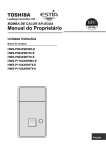
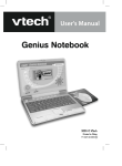
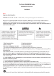
AIR CONDITIONER (MULTI TYPE) Owner’s Manual Outdoor Unit For commercial use Model name: <Heat Pump Model> MCY-MAP0401HT MCY-MAP0501HT MCY-MAP0601HT MCY-MAP0401HT2D MCY-MAP0501HT2D MCY-MAP0601HT2D MCY-MAP0401HTZ MCY-MAP0501HTZ MCY-MAP0601HTZ MCY-MAP0401HT2DZ MCY-MAP0501HT2DZ MCY-MAP0601HT2DZ MCY-MAP0401HTZG MCY-MAP0501HTZG MCY-MAP0601HTZG MCY-MAP0401HT2DZG MCY-MAP0501HT2DZG MCY-MAP0601HT2DZG Owner’s Manual English –1– Original instruction Please read carefully through these instructions that contain important information which complies with the “Machinery” Directive (Directive 2006/42/EC), and ensure that you understand them. Thank you very much for purchasing TOSHIBA Air Conditioner. Please read this owner’s manual carefully before using your Air Conditioner. • Be sure to obtain the “Owner’s manual” and “Installation manual” from constructor (or dealer). Request to constructor or dealer • Please clearly explain the contents of the Owner’s manual and hand over it. ADOPTION OF NEW REFRIGERANT This Air Conditioner adopts a new refrigerant HFC (R410A) instead of the conventional refrigerant R22 in order to prevent destruction of the ozone layer. Generic Denomination: Air Conditioner Definition of Qualified Installer or Qualified Service Person The air conditioner must be installed, maintained, repaired and removed by a qualified installer or qualified service person. When any of these jobs is to be done, ask a qualified installer or qualified service person to do them for you. A qualified installer or qualified service person is an agent who has the qualifications and knowledge described in the table below. Agent Qualifications and knowledge which the agent must have • Qualified installer • The qualified installer is a person who installs, maintains, relocates and removes the air conditioners made by Toshiba Carrier Corporation. He or she has been trained to install, maintain, relocate and remove the air conditioners made by Toshiba Carrier Corporation or, alternatively, he or she has been instructed in such operations by an individual or individuals who have been trained and is thus thoroughly acquainted with the knowledge related to these operations. • The qualified installer who is allowed to do the electrical work involved in installation, relocation and removal has the qualifications pertaining to this electrical work as stipulated by the local laws and regulations, and he or she is a person who has been trained in matters relating to electrical work on the air conditioners made by Toshiba Carrier Corporation or, alternatively, he or she has been instructed in such matters by an individual or individuals who have been trained and is thus thoroughly acquainted with the knowledge related to this work. • The qualified installer who is allowed to do the refrigerant handling and piping work involved in installation, relocation and removal has the qualifications pertaining to this refrigerant handling and piping work as stipulated by the local laws and regulations, and he or she is a person who has been trained in matters relating to refrigerant handling and piping work on the air conditioners made by Toshiba Carrier Corporation or, alternatively, he or she has been instructed in such matters by an individual or individuals who have been trained and is thus thoroughly acquainted with the knowledge related to this work. • The qualified installer who is allowed to work at heights has been trained in matters relating to working at heights with the air conditioners made by Toshiba Carrier Corporation or, alternatively, he or she has been instructed in such matters by an individual or individuals who have been trained and is thus thoroughly acquainted with the knowledge related to this work. • Qualified service person • The qualified service person is a person who installs, repairs, maintains, relocates and removes the air conditioners made by Toshiba Carrier Corporation. He or she has been trained to install, repair, maintain, relocate and remove the air conditioners made by Toshiba Carrier Corporation or, alternatively, he or she has been instructed in such operations by an individual or individuals who have been trained and is thus thoroughly acquainted with the knowledge related to these operations. • The qualified service person who is allowed to do the electrical work involved in installation, repair, relocation and removal has the qualifications pertaining to this electrical work as stipulated by the local laws and regulations, and he or she is a person who has been trained in matters relating to electrical work on the air conditioners made by Toshiba Carrier Corporation or, alternatively, he or she has been instructed in such matters by an individual or individuals who have been trained and is thus thoroughly acquainted with the knowledge related to this work. • The qualified service person who is allowed to do the refrigerant handling and piping work involved in installation, repair, relocation and removal has the qualifications pertaining to this refrigerant handling and piping work as stipulated by the local laws and regulations, and he or she is a person who has been trained in matters relating to refrigerant handling and piping work on the air conditioners made by Toshiba Carrier Corporation or, alternatively, he or she has been instructed in such matters by an individual or individuals who have been trained and is thus thoroughly acquainted with the knowledge related to this work. • The qualified service person who is allowed to work at heights has been trained in matters relating to working at heights with the air conditioners made by Toshiba Carrier Corporation or, alternatively, he or she has been instructed in such matters by an individual or individuals who have been trained and is thus thoroughly acquainted with the knowledge related to this work. This appliance is not intended for use by person (including children) with reduced physical, sensory or mental capabilities, or lack of experience and knowledge, unless they have been given supervision or instruction concerning use of the appliance by a person responsible for their safety. Contents 1 Precautions for safety . . . . . . . . . . . . . . . . . . . . . . . . . . . . . . . . . . . . . . . . . . . . . . . . . . 2 2 Part names . . . . . . . . . . . . . . . . . . . . . . . . . . . . . . . . . . . . . . . . . . . . . . . . . . . . . . . . . . . 4 3 Part names and functions of the remote controller . . . . . . . . . . . . . . . . . . . . . . . . . . 6 4 Correct usage . . . . . . . . . . . . . . . . . . . . . . . . . . . . . . . . . . . . . . . . . . . . . . . . . . . . . . . . . 8 5 Timer operation . . . . . . . . . . . . . . . . . . . . . . . . . . . . . . . . . . . . . . . . . . . . . . . . . . . . . . . 9 6 Installation . . . . . . . . . . . . . . . . . . . . . . . . . . . . . . . . . . . . . . . . . . . . . . . . . . . . . . . . . . 10 7 Notes on operations and performance . . . . . . . . . . . . . . . . . . . . . . . . . . . . . . . . . . . 10 8 Louver direction . . . . . . . . . . . . . . . . . . . . . . . . . . . . . . . . . . . . . . . . . . . . . . . . . . . . . . 11 9 Tips for saving energy and comfortable performance . . . . . . . . . . . . . . . . . . . . . . . 16 10 Maintenance . . . . . . . . . . . . . . . . . . . . . . . . . . . . . . . . . . . . . . . . . . . . . . . . . . . . . . . . . 17 11 When the following symptoms are found . . . . . . . . . . . . . . . . . . . . . . . . . . . . . . . . . 18 12 Specifications . . . . . . . . . . . . . . . . . . . . . . . . . . . . . . . . . . . . . . . . . . . . . . . . . . . . . . . . 19 1-EN 2-EN 1 Warning indications on the air conditioner unit Warning indication WARNING ELECTRICAL SHOCK HAZARD Disconnect all remote electric power supplies before servicing. WARNING Moving parts. Do not operate unit with grille removed. Stop the unit before the servicing. CAUTION High temperature parts. You might get burned when removing this panel. CAUTION Do not touch the aluminum fins of the unit. Doing so may result in injury. CAUTION BURST HAZARD Open the service valves before the operation, otherwise there might be the burst. 3-EN Precautions for safety The manufacturer shall not assume any liability for the damage caused by not observing the description of this manual. Description WARNING WARNING General ELECTRICAL SHOCK HAZARD Disconnect all remote electric power supplies before servicing. • Carefully read Owner’s Manual before starting the air conditioner. There are many important things to keep in mind for daily operation. • Ask for installation to be performed by the dealer or a professional. Only a qualified installer (*1) is able to install an air conditioner. If a non-qualified person installs an air conditioner, it may result in problems such as fire, electric shock, injury, water leakage, noise and vibration. • Do not use any refrigerant different from the one specified for complement or replacement. Otherwise, abnormally high pressure may be generated in the refrigeration cycle, which may result in a failure or explosion of the product or an injury to your body. • Places where the operation sound of the outdoor unit may cause a disturbance. (Especially at the boundary line with a neighbor, install the air conditioner while considering the noise.) WARNING Moving parts. Do not operate unit with grille removed. Stop the unit before the servicing. Transportation and storage • When transporting the air conditioner, wear shoes with protective toe caps, protective gloves, and other protective clothing. • When transporting the air conditioner, do not take hold of the bands around the packing carton. You may injure yourself if the bands should break. • When stacking the packing cartons for storage or transportation, heed the precautions written on the packing cartons. Failure to heed the precautions may cause the stack to collapse. • You shall ensure that the air conditioner is transported in stable condition. If you find any part of the product broken, contact your dealer. Installation CAUTION • Only a qualified installer (*1) or qualified service person (*1) is allowed to carry out the electrical work of the air conditioner. Under no circumstances must this work be done by an unqualified individual since failure to carry out the work properly may result in electric shocks and / or electrical leaks. • After the installation work has been completed, have the installer explain about the circuit breaker positions. In the event that error has occurred in the air conditioner, set the circuit breaker to the OFF position, and contact a service person. • If you install the unit in a small room, take appropriate measures to prevent the refrigerant from exceeding the limit concentration even if it leaks. Consult the dealer from whom you purchased the air conditioner when you implement the measures. Accumulation of highly concentrated refrigerant may cause an oxygen deficiency accident. • Do not install the air conditioner in a location that may be subject to a risk of expire to a combustible gas. If a combustible gas leaks and becomes concentrated around the unit, a fire may occur. • Be sure to use the company-specified products for the separately purchased parts. Use of non-specified products may result in fire, electric shock, water leakage, etc. Have the installation performed by a professional. • Confirm that earthing is performed correctly. High temperature parts. You might get burned when removing this panel. CAUTION Do not touch the aluminum fins of the unit. Doing so may result in injury. Operation • Before opening the intake grille of the indoor unit or service panel of the outdoor unit, set the circuit breaker to the OFF position. Failure to set the circuit breaker to the OFF position may result in electric shocks through contact with the interior parts. Only a qualified installer (*1) or qualified service person (*1) is allowed to remove the intake grille of the indoor unit or service panel of the outdoor unit and do the work required. • Inside the air conditioner are high-voltage areas and rotating parts. Due to the danger of electric shocks or of your fingers or physical objects becoming trapped in the rotating parts, do not remove the intake grille of the indoor unit or service panel of the outdoor unit. When work involving the removal of these parts is required, contact a qualified installer or a qualified service person. • Do not move or repair any unit by yourself. Since there is high voltage inside the unit, you may get electric shock when removing the cover and main unit. • Use of a stand more than 50 cm high to clean the filter of the indoor unit or to carry out other such jobs constitutes working at heights. Due to the danger of falling off the stand and injuring yourself while working at heights, this kind of work should not be done by unqualified individuals. When this kind of work must be carried out, do not do it yourself but ask a qualified installer or a qualified service person to do it for you. • Do not touch the aluminum fin of the outdoor unit. You may injure yourself if you do so. If the fin must be touched, do not touch it yourself but contact a qualified installer or a qualified service person. • Do not climb onto or place objects on top of the outdoor unit. You may fall or the objects may fall off of the outdoor unit and result in injury. • Do not place any combustion appliance in a place where it is directly exposed to the wind of air conditioner, otherwise it may cause imperfect combustion. • When the air conditioner is operated with a combustion appliance in the same place, be careful of ventilation to let fresh air enter the room. Poor ventilation causes oxygen shortage. CAUTION BURST HAZARD Open the service valves before the operation, otherwise there might be the burst. –2– EN 4-EN –3– • When the air conditioner is used in a closed room, be careful of sufficient ventilation of the room. Poor ventilation causes oxygen shortage. • Do not expose your body to cool air directly for a long time and do not cool yourself excessively. Doing so may result in deteriorated physical condition and ill health. • Never insert your finger or a stick into the air intake or discharge. Doing so may result injury as the fan is rotating at high speed inside the unit. • Consult the shop where you purchased the air conditioner if air conditioning (cooling and heating) is not performed properly as a refrigerant leakage may be the cause. Confirm the repair details with a qualified service person (*1) when the repair includes additional charging of the refrigerant. • Be sure to stop running the air conditioner and turn off the breaker before cleaning. Otherwise, injury may result as the fan is rotating at high speed inside the unit. Repairs • When you have noticed that some kind of error (such as when an error display has appeared, there is a smell of burning, abnormal sounds are heard, the air conditioner fails to cool or heat or water is leaking) has occurred in the air conditioner, do not touch the air conditioner yourself but set the circuit breaker to the OFF position, and contact a qualified service person. Take steps to ensure that the power will not be turned on (by marking “out of service” near the circuit breaker, for instance) until qualified service person arrives. Continuing to use the air conditioner in the error status may cause mechanical problems to escalate or result in electric shocks, etc. • If you have discovered that the fan grille is damaged, do not approach the outdoor unit but set the circuit breaker to the OFF position, and contact a qualified service person to have the repairs done. Do not set the circuit breaker to the ON position until the repairs are completed. • If you have discovered that there is a danger of the indoor unit’s falling, do not approach the indoor unit but set the circuit breaker to the OFF position, and contact a qualified installer or a qualified service person to refit the unit. Do not set the circuit breaker to the ON position until the unit has been refitted. • If you have discovered that there is a danger of the outdoor unit’s toppling over, do not approach the outdoor unit but set the circuit breaker to the OFF position, and contact a qualified installer or a qualified service person to have the improvements or refitting done. Do not set the circuit breaker to the ON position until the improvements or refitting is completed. • Do not customize the unit. Doing so may result in fire, electric shock, etc. • Check whether the installation base and other equipment have become deteriorated after being used for a long time. Leaving them such condition may result in the unit’s falling down and causing injury. • Do not leave flammable sprays or other flammable materials near the air conditioner, and do not spray flammable aerosol directly to the air conditioner. They may catch fire. • Be sure to stop running the air conditioner and turn off the breaker before cleaning. Otherwise, injury may result as the fan is rotating at high speed inside the unit. • Ask for cleaning of the air conditioner to be performed by the dealer. Cleaning the air conditioner in an improper manner may cause damage to plastic parts, insulation failure of electric parts, etc. and result in a malfunction. In the worst case, it may result in water leakage, electric shock, smoke emission and fire. • Do not put a water container such as a vase on the unit. Water intrusion into the unit may occur and it may cause deterioration of electric insulation and result in electric shock. (*1) Refer to the “Definition of Qualified Installer or Qualified Service Person.” Information on the transportation, handling and storage of the carton Examples of indication on the carton Symbol Description Symbol Description Symbol Description Relocation • When the air conditioner is to be relocated, do not relocate it yourself but contact a qualified installer or a qualified service person. Failure to relocate the air conditioner properly may result in electric shocks and / or a fire. Keep dry Do not drop Do not lay down CAUTION To disconnect the appliance form the main supply • This appliance must be connected to the mains by means of a switch with a contact separation of at least 3 mm. Fragile Stacking height (12 cartons can 11 cartons be stacked in this case) Do not walk on this carton Installation fuse (all types can be used) must be used for the power supply line of this air conditioner. Installation • Certainly lay the drain hose for perfect draining. Bad drainage may cause flooding in the house and getting furniture wet. • Make sure to connect the air conditioner to an exclusive power supply of the rated voltage, otherwise the unit may break down or cause a fire. • Confirm that the outdoor unit are fixed on the base. Otherwise, falling down of the units or other accidents may occur. Operation • Do not use this air conditioner for special purpose such as preserving food, precision instruments, art objects, breeding animals, car, vessel, etc. • Do not touch any switches with wet finger, otherwise you may get an electric shock. • If the air conditioner will not be used for a considerably long time, turn off the main switch or the circuit breaker, for safety. • To make the air conditioner operate in its original performance, operate it within the range of the operating temperature specified in the instructions. Otherwise it may cause a malfunction, or water leak from the unit. • Prevent any liquid from falling into the remote controller. Do not spill juice, water or any kind of liquid. • Do not wash the air conditioner. Doing so may result in electric shock. 5-EN This side up CAUTION Injury possibility. Don’t handle with packing band, or may get injured in case of broken band. Do not step Handle with care Stacking notice. In case that cardboard boxes protrude out of pallet when stacking. Lay a 10 mm thick plywood over the pallet. 6-EN 2 Connectable indoor units Model type Model Name 4-way cassette MMU-AP✽✽✽✽H-E Compact 4-way cassette MMU-AP✽✽✽✽MH-E 2-way cassette 1-way cassette Part names Outdoor unit MMU-AP✽✽✽✽WH-E MMU-AP✽✽✽✽YH-E Air intake They are provided at rear and left sides. MMU-AP✽✽✽✽SH-E Concealed duct, standard type MMD-AP✽✽✽✽BH-E Concealed duct, high static pressure MMD-AP✽✽✽✽H-E Slim duct MMD-AP✽✽✽✽SPH-E Ceiling MMC-AP✽✽✽✽H-E Floor standing cabinet type MML-AP✽✽✽✽H-E Floor standing concealed type MML-AP✽✽✽✽BH-E Floor standing MMF-AP✽✽✽✽H-E High-wall compact MMK-AP✽✽✽✽MH-E * For details on these models, read the owner’s manuals that come with the indoor units. High-wall MMK-AP✽✽✽✽H * For details on these models, read the owner’s manuals that come with the indoor units. ConsoleType MML-AP✽✽✽✽NH-E * For details on these models, read the owner’s manuals that come with the indoor units. Air discharge Hot air is discharged when cooling operation is performed. Cold air is discharged when heating operation is performed. Power source hole Refrigerant pipe connecting hole Connecting valve is included inside here. Fixing leg Equipped on the electrical control box. Indoor unit ◆ 4-Way Cassette Type Discharge louver Controls discharge air directions. Knob Open / close the return air grille. Earth screw Equipped on the electrical control box. Return air grille Air in the room is taken in through here. ◆ Compact 4-Way cassette Type Knob Open / close the return air grille. Earth screw Equipped on the electrical control box. Return air grille Air in the room is taken in through here. 7-EN –4– Discharge louver Controls discharge air directions. EN 8-EN –5– ◆ 2-way Cassette Type Return air grille Air in the room is taken in through here. ◆ Concealed Duct Standard Type Earth screw Equipped on the electrical control box. Air discharge The air discharge duct is connected. Earth screw Equipped on the electrical control box. Return air grille Air in the room is taken in through here. Air filter Filters out dust. (Inside the return air grille) Discharge louver Controls discharge air directions. ◆ Concealed Duct High Static Pressure Type Air filter Filters out dust. (Inside the return air grille) Air discharge The air discharge duct is connected. Return air grille The return air duct is connected. Drain pan Earth screw Equipped on the electrical control box. ◆ 1-way Cassette Type MMU-AP007✽YH✽ to AP012✽YH✽ Earth screw Equipped on the electrical control box. ◆ Slim Duct Type Discharge louver Controls discharge air directions. Return air grille The return air duct is connected. Air filter Filters out dust. (Locally procured) Air filter Filters out dust. (Inside the return air grille) Return air grille Air in the room is taken in through here. MMU-AP015✽SH✽ to AP024✽SH✽ Knob Open / close the return air grille. Earth screw Equipped on the electrical control box. Air discharge The air discharge duct is connected. ◆ Ceiling Type Discharge louver Controls discharge air directions. Earth screw Equipped on the electrical control box. Discharge louver Controls discharge air directions. Air filter Filters out dust. (Inside the return air grille) Return air grille Air in the room is taken in through here. Earth screw Equipped on the electrical control box. Return air grille Air in the room is taken in through here. Air filter Filters out dust. (Inside the return air grille) 9-EN 10-EN 3 ◆ Floor Standing Cabinet Type Discharge louver Controls discharge air directions. Air filter Filters out dust. (Inside the return air grille) Part names and functions of the remote controller This remote controller can control up to 8 indoor units. Display section Earth screw All indicators are displayed in the display example below. Actually, only the selected options will be displayed. • blinks on the display of the remote controller the first time the power switch is turned on. • The initial settings progress while is blinking. Start to use the remote controller after has disappeared. Return air grille Air in the room is taken in through here. ◆ Floor Standing Concealed Type Air discharge 18 1 789 Air intake Air in the room is taken in through here. 2 3 4 5 6 21 15 16 ◆ Floor Standing Type Metal fittings Vertical louver Automatically directs the airflow horizontally at regular intervals. Earth screw Equipped on the electrical control box. Drain pan Water collected here is drained out through the drain pipe. 1 Metal fittings (left / right) 2 3 4 5 6 11-EN TIME SET CL FAN MODE SAVE VENT SWING/FIX UNIT LOUVER Operation section NOTE Front panel (lower) Air intake Air in the room is taken in through here. ON / OFF TIMER SET The LCD may temporarily be blurred due to static electricity. Air filter Filters out dust. (Inside the return air grille) Earth screw Equipped on the electrical control box. Air filter Filters out dust TEMP. FILTER RESET TEST Drain funnel (with strainer) Accessory to be attached at the site Discharge louver Controls discharge air directions. Display section –6– SETTING indicator Displayed when setting the timer or other functions. Operation mode indicator Indicates the operation mode selected. Error indicator Displayed when the protective device activates or an error occurs. 17 10 19 11 20 12 13 14 7 8 TEST run indicator Displayed during test run. Louver position display Indicates the louver position. * Only for 4-way cassette, 1-way cassette, 2-way cassette, ceiling types Time display Indicates time concerning the timer. (Indicates an error code when an error occurs) Timer mode indicator Displays the timer mode. Filter indicator Reminder to clean the air filter. EN 12-EN –7– 18 1 789 2 3 4 5 6 21 15 16 9 Swing indicator Displayed during up / down movement of the louver. 10 Set temperature display The selected set temperature is displayed. 11 Remote controller sensor indicator Displayed when the remote controller sensor is used. 12 Pre-heat indicator Displayed when the heating mode is energized or defrost cycle is initiated. While this indication is displayed, the indoor fan stops or operate in fan mode. 13 No function indicator Displayed when the function requested is not available on that model. 14 Fan speed indicator Indicates the selected fan speed: (Auto) (High) (Medium) (Low) 15 Louver Number display (exapmle:01, 02, 03, 04) 16 Louver lock indicator Displayed when a louver is locked. (4-way cassette type only) 17 UNIT No. display Operation section 17 Once the settings have been configured, all you need to do is push the button from then on. 1 8 10 19 11 20 12 13 14 19 Operation mode controlled indicator Displayed when MODE button is pushed while operation mode is fixed to cool or heat by the air conditioner administrator. 10 4 11 5 3 18 Central control indicator Displayed when the air conditioner is controlled centrally and used with central control devices such as the central remote controller. If the use of the remote controller is prohibited by the central control, blinks when the ON / OFF, MODE, or TEMP. button on the remote controller is pushed, and the buttons do not function. (Settings that can be configured on the remote controller differ depending on the mode of the central control. For details, read the Owner’s Manual of the central remote controller.) 9 12 2 1 button (Fan speed select button) Selects the desired Fan speed. * Not available for the concealed duct high static pressure and fresh air intake type. Only “High” is displayed. 2 3 button (Timer set button) Use to setup the timer. button (TEST button) Use only for service. (During normal operation, do not use this button.) 4 7 6 8 9 Operation lamp Lights up during running. Blinks when an error occurs or the protective device activates. button Turns on the unit when pushed, and turns off when pushed again. 10 button (Operation mode select button) Selects desired operation mode. button Use when a ventilator (commercially-available) is connected. Push the button to turn on / off the ventilator. Turning on / off the air-conditioner also turns on / off the ventilator. ” appears on * No ventilator is connected if “ the remote controller display after pushing the button. 20 Operation ready display This display appears on some models. 21 Service display Displayed while the protective device works or a trouble occurs. 5 button (Filter reset button) FILTER” indication after cleaning. Resets “ 6 button (Power save operation) No function. 7 SWING/FIX button Use to select automatic swing or fixed louver position. * Not available for concealed duct, slim duct, floor concealed and floor standing cabinet fresh air intake types. Displays the number of the indoor unit selected. Also displays error code of indoor and outdoor units. 13-EN 14-EN 4 1 8 UNIT LOUVER Preparation 10 4 11 5 3 11 • When you use the air conditioner for the first time or change the settings, follow the procedures below. From next time, pushing the button starts running of the air conditioner with the chosen settings. 9 12 2 Turn on the power switch • When turned on, the separation line appears and blinks on the remote controller display. * The remote controller will not work for about 1 minute after turning on the power. This is not a malfunction. REQUIREMENT • Keep the power switch turned on during use. • When you resume using the air conditioner after a long period of disuse, turn on the power switch at least 12 hours before starting running. 7 6 button (Unit / Louver select button) Operations Selects a unit number (left) and louver number (right). UNIT button: If two or more indoor units are controlled by one remote controller, use this button to select a unit to adjust its air blow direction. LOUVER button: (4-way cassette type only) Selects a louver to control when adjusting the louver lock setting or wind direction setting separately for each louver. 12 Correct usage Changing the fan speed 1 TEMP. TIMER SET button Adjusts the set temperature. Select the desired set point by pushing or TEMP. FAN TIME FILTER RESET TEST TEMP. 1 OPTION: Remote controller sensor Normally the temperature sensor of the indoor unit senses the temperature. The temperature around the remote controller can also be sensed. For details, contact your dealer. * Do not use the function when the air conditioner is controlled in a group. 2 SET CL ON / OFF 1 MODE 2 SAVE VENT SWING/FIX UNIT LOUVER Push the button. The operation lamp lights up. Push the “MODE ” button to select a operation mode. Each time you push the button, the operation mode and its icon change in the following order: Heat Dry Cool Fan Push the “FAN ” button to select a fan speed. • Each time you push the button, fan speed and its indication change in the following order: (“ Auto” cannot be selected in the FAN mode.) Auto High Medium Low • When heating, if the room does not heat up using “ Low”, select “ High” or “ Medium”. • The temperature sensor detects the return air temperature at the indoor unit, which may slightly differ from the actual room temperature depending on installation condition. Set temperature is a target of room temperature. • The fan speed selection function is not available for the concealed duct high static type. Fan speed is fixed and the indicator is fixed to “ High”. (Dehumidify) “ Dry” is not available for the concealed duct high static type. 3 Push the button to stop running. The operation lamp turns off. EN 15-EN –8– 16-EN –9– Changing the set temperature 1 Power save operation Push the “TEMP. ” buttons. Push to increase the temperature, and to decrease the temperature. (The set temperature cannot be changed in the fan mode.) Timer operation Select a timer type from the following three: (Max. 168 hours) Displayed during Power save operation. NOTE TEMP. OFF timer Repeat-OFF timer On timer : Stops running after the specified period. : Stops running after the specified period every time you use the air conditioner. : Starts running after the specified period. ON / OFF Setting the timer When cooling Running starts in approximately 1 minute. TIMER SET TIME When heating • The air conditioner may continue running in the fan mode for about 30 seconds after stopping heating. • The heated air comes out after a 3 to 5 minutes of pre-heating with the indoor fan kept turned off. (The pre-heat indicator is displayed on the remote controller.) • The fan speed becomes extremely low when the room temperature has reached the set temperature. However, for concealed duct high static types, the fan speed does not change after the temperature has reached to the set temperature. 5 FILTER RESET TEST 1 2 SET CL FAN MODE SAVE VENT SWING/FIX UNIT LOUVER Save button 1 2 Push the button during operation. • Power save operation is activated. • is appeared. Push button to deactivate Power save operation. • is disappeared. 3 1 Push the button. Each time you push the button, the timer mode and indication change in the following order: • 34 hours (*2) indicates 1 day (24 hours). indicates 10 hours. (Total: 34 hours) NOTE • Capability of the air conditioner is saved during the Power save operation. The room may not become cool or warm enough. • Power save operation will not be deactivated by stop operation, change operation mode or turn off the power switch. Off Off On (Off timer) (Repeat Off timer) (On timer) 3 No indication (Timer function is deactivated) • 2 and the time indicator blink. Push the buttons to set the period of time until the timer actions. • The time setting increases in 0.5-hour (30minute) increments each time you push . The setting increases in 1-hour increments if it is over 1d (24 hours). The maximum is 7d (168 hours). On the remote controller, settings between 0.5h and 23.5h (*1) are displayed as is. If it is over 24 hours (*2), the days and hours appear. • The time setting decreases in 0.5-hour (30minute) decrements (0.5 hours to 23.5 hours) or 1-hour decrements (24 hours to 168 hours) each time you push . Example of remote controller display Days Hours Push the button. • disappears, the time indication is displayed, and or display flashes. (When using the ON timer, all indications other than the time and turn off.) Cancelling the timer 1 Push the button. The timer indicator disappears. NOTE • When using Repeat OFF timer, pushing the button after stopping by the timer starts running again and the timer will stop the running again after the specified period. • When using OFF timer, the timer indication temporarily disappears for about 5 seconds by pushing the SWING/FIX button. This occurs due to the processing in the remote controller, and is not a malfunction. • 23.5 hours (*1) 17-EN 18-EN 6 7 Installation Notes on operations and performance Location Check before operation • Avoid installing near machines emitting high frequency waves. • Not suitable for chemical plants such as liquefied carbon dioxide refrigerant plants. • Do not install the air conditioner in locations where iron or other metal dust is present. If iron or other metal dust adheres to or collects on the interior of the air conditioner, it may spontaneously combust and start a fire. • A failure may occur in certain locations such as the following: • Areas with large amount of oil droplets (including machine oil) or vapors • Salty areas near oceans, etc. • Hot springs emitting sulfidizing gas, etc. • Heavily acidic or alkaline places. Special maintenance or parts are required for use in the above places. For details, contact the dealer where you purchased the product. • Leave an enough space around the air intake and discharge of the outdoor unit so that the ventilation is not restricted. • Avoid places where strong wind may blow against the air intake and discharge of the outdoor unit. • Attach a snow stand, snow hood, etc. to the outdoor unit for use in snowfall areas. For details, contact the dealer where you purchased the product. • Make sure drain water from the outdoor unit is emitted into places with good drainage. • Make sure the air filter is attached to the indoor unit. If not, dust may accumulate on the heat exchanger or other parts in the air conditioner and cause a water leak. • Keep a distance of at least 1 m between the air conditioner / remote controller and a TV or radio. Failure to observe this precaution may cause visual disturbance or noise. • Leave a distance of at least 1.5 m between the air discharge and a fire alarm. If this precaution is not observed, the alarm may not work properly or detect fire in case of fire. • Turn on the power switch at least 12 hours before starting operation. • Make sure the earth wire is securely connected. • Make sure the air filter is attached to the indoor unit. Heating performance • A heat pump system, which gathers outside heat and emits it into a room, is used for heating. When the outside air temperature falls, the heating capacity of the unit is reduced. • When the outside temperature is low, it is recommended that you also use other heating equipment. Defrosting during heating • If frost falls on the outdoor unit during heating, defrosting is automatically performed (for approximately 2 - 10 minutes) to increase the heating effect. • The fan of the indoor unit is stopped during defrosting. Be careful of operation sounds 3-minute protection • Locate the unit in a place secure enough so that the sounds and vibrations do not increase. • If something is placed near the air discharge of the outdoor unit, noise may increase. • Be careful not to disturb your neighbors with cool / warm air or noise coming from the air discharge of the outdoor unit. The outdoor unit will not operate for approximately 3 minutes after the air conditioner has been immediately restarted after stopping, or the power switch has been turned on. This is to protect the system. Protective device (High pressure switch) The high pressure switch stops the air conditioner automatically when excessive load is applied to the air conditioner. If the protective device activates, the unit’s running stops and the operation lamp blinks. When the protective device activates, the indicator and the check code are displayed on the remote controller. The protective device may activate in the following cases: During cooling • When the air intake or air discharge of the outdoor unit is blocked. • When strong wind blows continuously against the air discharge of the outdoor unit. During heating • When dust or dirt is excessively adhered to the air filter of the indoor unit. • When the air discharge of the indoor unit is blocked. NOTE When the protective device activates, turn off the power switch, remove the cause, and then restart running. Power failure • In the case of a power failure, all operations stop. • To resume operations, push the ON / OFF button. Fan rotation of a stopped indoor unit • While other indoor units operate, the fans on indoor units in stand-by mode rotate for several minutes approximately once per one hour to protect the machines. EN 19-EN – 10 – 20-EN – 11 – Cooling / Heating operations Each unit can be controlled individually. However, indoor units connected to the same outdoor unit cannot perform cooling and heating simultaneously. When you attempt simultaneous operation, indoor units performing cooling are stopped, and the running preparation indicator is displayed on the remote controller. An indoor unit performing heating continues running. When you attempt an operation without the configured settings, the running preparation indicator is displayed on the remote controller and operation stops. If operation is fixed to cooling or heating by the air conditioner administrator, only the configured settings apply to the operation. Characteristics of heating • Air does not come out immediately after heating starts. Heated air comes out after 3 to 5 minutes (depending on the room / outside temperatures), after the indoor heat exchanger warms up. • When the outside temperature increases, the outdoor unit may stop. 8 Louver direction NOTE To improve the cooling / heating performance, change the louver angle for each operation. The characteristics of air: Cool air falls, and warm air rises. CAUTION 4-way cassette type, 2-way cassette type, 1-way cassette type, ceiling type ◆ To set the louver direction 1 Point the louver horizontally during cooling If pointing downward for cooling, dew may form on the surface of the air discharge or louver and may drop down. Push the SWING/FIX button during running. The louver direction changes with each push of the button. ▼ For heating Point the louver downward. If not pointing downward, hot air may not reach the floor. NOTE Initial setting • If pointing horizontally for cooling, dew may form on the surface of the cabinet or louver and may drop down. • If pointing horizontally for heating, the room temperature may be uneven. • Do not handle the louver manually. Doing so may cause a failure. Use the SWING / FIX button on the remote controller to adjust the angle. ▼ For cooling Point the louver horizontally. If pointing downward, dew may form on the surface of the air discharge port and may drop down. Initial setting ▼ For fan Select a wind direction. Initial setting ◆ To start swinging 1 SWING/FIX Push the button repeatedly to set the louver direction to the lowest position, then SWING/FIX push again. The SWING indicator is displayed and the louver begins swinging. ▼ In all operations Repeat 21-EN 22-EN ◆ To stop swinging 1 3 4-way cassette type only SWING/FIX Push the button at the desired position while the louver is swinging. SWING/FIX • Push the button repeatedly to change the louver position again. SWING/FIX * However, even if the button is pushed while the louver is swinging, one of the indications below may sometimes be displayed and may not set the louver to the highest position. ◆ To set the louvers individually 1 Push the button (left side of the button) during running to select a unit. The unit number changes each time you push the button. ▼ Indications when swinging is stopped FAN / HEAT Unit No. 1-4 button. Push the button to finish the setting. ▼ Standard swing All four louvers swing simultaneously at the same angle. (5) * When cooling or drying, (4) and (5) are not displayed. ◆ Setting the swing pattern UNIT LOUVER Push the button (right side of the button) to select a louver. Each time you push the button, the indicator on the left of the remote controller changes as follows: 1 2 No display * When no louver number is displayed, all 4 louvers are selected. UNIT LOUVER Push the button (left side of the button) to select a unit. The unit number changes each time you push the button. Unit No. 1-2 No display COOL / DRY operation SWING/FIX FIX for at least 4 seconds while the operation is stopped. blinks. Push and hold the Unit No. 1-1 3 Push the type. ▼ Dual swing (Recommended for heating) • Adjoining louvers alternately point horizontally and downward to heat the room evenly. • Air blown downward reaches the floor, and air blown horizontally is spread to circulate heat. Unit No. 1-3 Unit No. 1-4 The fan of the selected unit runs, and the louver swings. ◆ Unit select Horizontal Horizontal Downward Downward buttons to select a swing Electrical control box • When two or more indoor units are controlled with one remote controller, the louver direction can be set for each indoor unit by selecting them individually. UNIT LOUVER • To set louver direction individually, push the button (left side of the button) to display an indoor unit number in the control group. Then set the louver direction of the displayed indoor unit. • When no indoor unit number is displayed, all indoor units in the control group can be controlled simultaneously. UNIT LOUVER • Each time you push the (left side of the button), the indication changes as follows: Unit No. 1-1 Unit No. 1-4 (6) (4) Push the Swing Louver No. No display (3) (7) ▼ Indications when swinging is stopped FAN / HEAT operation (2) 4 5 Unit No. 1-3 • When no unit number is displayed, all units are selected. 2 SWING/FIX Unit No. 1-2 No display COOL / DRY In this case, push the button again after 2 seconds. • In COOL / DRY operation, the louver does not stop as it directs downward. If stopping the louver as it directs downward during swing operation, it stops after moving to the third position from the highest position. (1) UNIT LOUVER Unit No. 1-1 SWING/FIX Push the button to confirm the direction of the selected louver. Each time you push the button, the indication changes as follows: Unit No. 1-2 Unit No. 1-3 03 Horizontal Refrigerant pipe Swing code 04 02 Swing code 0001 Drain pipe 01 Movement pattern Standard swing (factory default) 0002 Dual swing 0003 Cyclic swing Horizontal Downward Downward REQUIREMENT Do not set “0000”. (The louver may be damaged.) EN 23-EN – 12 – 24-EN – 13 – ▼ Cyclic swing (Recommended for cooling) All four louvers swing at different times like waves. ◆ Setting the louver lock 1 (2) (3) (4) (4) Set “0000” in Step 4 of “Setting the louver lock”. The mark disappears. UNIT LOUVER • When no unit number is displayed, all units are selected. (1) (2) ◆ Releasing the louver lock button (right side of the button) for at least 4 seconds while running is stopped. blinks. Push and hold the 2 (1) UNIT LOUVER Push the button (left side of the button) to select a unit. The unit number changes each time you push the button. Unit No. 1-1 (3) 0001 - 0005 (Louver position code) Unit No. 1-2 Unit No. 1-3 (1) (3) (4) 3 (2) (3) 2 04 Push and hold the and “TEMP. ” buttons for at least 4 seconds while running is stopped. blinks. “01” appears in CODE No. UNIT LOUVER Push the button (left side of the button) to select a unit The unit number changes each time you push the button. Unit No. 1-2 Unit No. 1-1 02 No display Unit No. 1-3 Unit No. 1-4 Drain pipe (1) The fan of the selected unit runs, and the louver swings. (4) 4 Push the buttons to select the direction of the louver you do not want to swing. (1) 0001 (4) 0004 (2) 0002 (3) 0003 (5) 0005 * If (4) or (5) is selected, condensation may occur during cooling. 5 6 25-EN 1 Refrigerant pipe Push the “TEMP. ” buttons to display the number of the louver to fix its direction. The selected louver swings. 0000 ◆ Adjusting the horizontal direction Electrical control box 03 The fan of the selected unit runs, and the louver swings. SET DATA Louver No. * F1 appears in the CODE No. section on the remote controller. This indicates that the louver 01 shown in the following figure is selected. Unit No. 1-4 (2) * Steps 1 - 3 and 5, 6 of “Setting the louver lock” also apply to releasing the lock. Push the button to confirm the setting. When the setting is confirmed, the mark lights up. (To set the louver lock of another unit, repeat from Step 2. To set another louver lock of the same unit, repeat from Step 3.) Push the 01 NOTE Even in louver lock mode, the louver temporarily moves in the following cases: • When the air conditioner is stopped • When heating starts • When defrosting • When thermo. off. 3 4 5 6 Push the “TEMP. ” buttons to change the CODE No. to “45”. Push the “TIME direction. ”buttons to select a Direction SET DATA Direction setting “0000” Smudging reduction position (reduces ceiling smudging) (factory default) “0002” Cold draft position (Less directly expose your body to cool air) Push the button to check the settings. The indicator stops blinking and stays lit, and the settings are confirmed. Push button to finish the setting. * If the cold draft position is selected, the ceiling smudging reduction effect will be reduced. button to finish the setting. 26-EN 4-way cassette type ▼ When cooling Point the louver horizontally. 2-way cassette type NOTE NOTE To improve the cooling / heating performance, change the louver angle for each operation. ▼ When cooling Point the louver horizontally to send cool air across the entire room. ◆ To set the air discharge direction to forward using a front air discharge unit (sold separately) ▼ When heating Point the louver downward. CAUTION ▼ When heating Point the louver downward to send heated air to the floor. When applying a front air discharge unit to the indoor unit, the 2-way air discharge function (forward + downward) is not available. Such use may lower the air temperature and cause water leakage. For details on the installation, read the installation manual that comes with a front air discharge unit (sold separately). 1. When sending air downward, bend the louvers evenly as shown in the following figure. If the air flow is blocked, water droplets may fall down from the air discharge. NO GOOD GOOD Louver 2. Set the angle of the louver to 40° or lower. If the angle is over 40°, droplets may fall down. 40° or lower Horizontal adjustment • The louver automatically closes when running is stopped. • In pre-heating mode, the louver points upward. The swing indication appears on the remote controller even in pre-heating mode, but the actual swing starts only after pre-heating is complete. ▼ 2-way and 3-way air discharge The air discharge can be changed to the 2-way or 3way type to suit your room shape and style. For details, contact the dealer where you purchased the air conditioner. When using a front air discharge unit (sold separately) for an indoor unit of the 1-way cassette type, follow the procedure below to change discharge direction: 1-way cassette type (SH series) Use the vertical grille behind the louver to even the room temperature. Vertical grille Vertical adjustment ▼ When cooling Point the louver horizontally to send cool air across the entire room. ▼ When cooling Move the louver manually and point it horizontally to send cool air across the entire room. Louver NOTE ▼ When heating Point the louver downward to send heated air to the floor. ▼ When heating Move the louver manually and point it downward to send heated air to the floor. When adjusting air direction horizontally, arrange the angles of the vertical grilles gradually as shown in the following figure. If the air flow is blocked, water droplets may fall down from the air discharge. NO GOOD Vertical grilles GOOD • The louver automatically closes when running is stopped. • In pre-heating mode, the louver points upward. The swing indication appears on the remote controller even in pre-heating mode, but the actual swing starts only after pre-heating is complete. 27-EN EN – 14 – 28-EN – 15 – Ceiling type Vertical adjustment ▼ When cooling Point the louver horizontally to send cool air across the entire room. ▼ When heating Point the louver downward to send heated air to the floor. 1-way cassette (YH series), and floor standing types ◆ Setting the direction and swinging 1 2 SWING/FIX Push the button during running. If 1 remote controller controls 2 or more indoor units, you can configure the direction setting for each unit individually. SWING/FIX button again while the louver Push the is swinging. You can stop the louver in your preferred position. TEMP. • The louver automatically points upward when running is stopped. • In pre-heating mode, the louver points upward. The swing indication appears on the remote controller even in pre-heating mode, but the actual swing starts only after pre-heating is complete. FILTER L RESET TEST ON / OFF TIMER SET FAN TIME SAVE A VENT SWING/FIX UNIT LOUVER SET CL Unit select Vertical adjustment ▼ When cooling Move the louver manually and point it horizontally to send cool air across the entire room. ▼ When cooling Point the louver horizontally to send cool air across the entire room. ▼ When heating Point the louver downward to send heated air to the floor. Vertical adjustment ▼ When heating Move the louver manually and point it downward to send heated air to the floor. 1,2 Horizontal adjustment To send air horizontally, point the vertical grilles inside the louver in your preferred direction. Horizontal adjustment ▼ Sending air in different directions Lift up the vertical louvers slightly and point them in your preferred directions. ◆ Unit select • When two or more indoor units are controlled with one remote controller, the louver direction can be set for each indoor unit by selecting them individually. UNIT LOUVER • To set louver direction individually, push the button (left side of the button) to display an indoor unit number in the control group. Then set the louver direction of the displayed indoor unit. • When no indoor unit number is displayed, all indoor units in the control group can be controlled simultaneously. UNIT LOUVER • Each time you push the (left side of the button), the indication changes as follows: No display Unit No. 1-1 Unit No. 1-4 29-EN Floor standing type MODE Horizontal adjustment When adjusting louver direction horizontally, point the vertical grille inside the horizontal louver in your preferred direction. 1-way cassette type (YH series) 2 1 NOTE To improve the cooling / heating performance, change the louver angle for each running mode. In this case, do not use the auto swing function. Unit No. 1-2 Unit No. 1-3 30-EN Floor standing cabinet type ▼ When cooling Move the louver manually and point it horizontally to send cool air across the entire room. ▼ When heating Move the louver manually and point it downward to send heated air to the floor. 9 ◆ Changing the air discharge Follow the procedure below to change the air discharge: 1 2 3 Tips for saving energy and comfortable performance To save energy and perform comfortable cooling and heating Remove the two fixing screws of the air discharge. (The fixing screws are to be reused) Clean the air filter often • A clogged air filter lowers the cooling / heating performance. Do not cool / heat too much WARNING Do not expose your body to cool air directly for a long time and do not cool yourself excessively. Doing so may result in deteriorated physical condition and ill health. Insert your hand into the air discharge and pull it up slightly, then remove the air discharge from the claw hook at the rear side. Check periodically! • Cooling / Heating too much is bad for your health. In particular, take care with handicapped / old people and children. Lift up the air discharge and remove it. Do not cool down too much! 4 5 Reverse the air discharge and reattach it to the main unit. Make sure that the four claw hooks (2 at the rear and 2 at the lower sides) are hooked into the mounting positions. Close windows and doors Cool / Heat the room evenly • Do not let cooled / heated air escape from the room. • Adjust the air direction with the louver. Exposing yourself to blowing air directly for a long time is bad for your health. Close. Be sure to tighten the air discharge with the removed fixing screws so that it does not come off. Air conditioner operating conditions For proper performance, operate the air conditioner under the following temperature conditions: Cooling operation Outdoor temperature : –5 °C to 43 °C (Dry-bulb temp.) Room temperature : 21 °C to 32 °C (Dry-bulb temp.), 15 °C to 24 °C (Wet-bulb temp.) [CAUTION] Heating operation Room relative humidity: less than 80 %. If the air conditioner operates in excess of this figure, the surface of the air conditioner may cause dewing. Outdoor temperature : -20 °C to 15.5 °C (Wet-bulb temp.) Room temperature : 15 °C to 28 °C (Dry-bulb temp.) If air conditioner is used outside of the above conditions, safety protection may operate. 31-EN – 16 – EN 32-EN – 17 – 10 Maintenance ◆ Floor standing cabinet type 1 WARNING For daily maintenance including Air Filter cleaning, make sure to ask the qualified service person particularly following models as the maintenance requires high-place work; • • • • • • • • 2 4-way cassette type Compact 4-way cassette type 2-way cassette type 1-way cassette type Ceiling type Concealed duct standard type Concealed duct high static type Slim duct type 3 Push down the upper part of the return air grille slightly, and then pull it toward you to remove it. Take out the air filter inside the return air grille. Vacuum dust or brush clean. • If heavily stained, it is more effective to wash in lukewarm water mixed with neutral detergent. • After washing, rinse it well, and dry it in the shade. • Reinstall the cleaned air filter. ◆ Floor standing type 1 3 CAUTION Do not push buttons with wet hands. Doing so may result in electric shock. Cleaning the air filters Vacuum dust or brush clean. • If heavily stained, it is more effective to wash in lukewarm water mixed with neutral detergent. • After washing, rinse it well, and dry it in the shade. • Reinstall the cleaned air filter. Remove the air filter. • Pull down the air filter toward you. • When the filter indicator is displayed on the remote controller, clean the air filters. • Ask qualified service person to clean the filters for the models listed in the warning on the top of this chapter. • Clogged filters may lower the cooling and heating performance. The “ • To attach the air filter, insert it into the unit and push it in. FILTER” indicator disappears. TEMP. FILTER RESET TEST ON / OFF TIMER SET FAN MODE TIME SAVE VENT SWING/FIX UNIT LOUVER SET CL When the cleaning is complete, push the “ FILTER RESET” button. 2 ◆ Floor Standing Concealed Type 1 2 Push down hook of the air filter on the front panel (Lower side). Pull the air filter toward you to remove it. • After washing, rinse it well, and dry it in the shade. 3 Front panel (Lower) Air filter knob 33-EN Vacuum dust or brush with water. • If heavily stained, it is more effective to wash in lukewarm water mixed with neutral detergent. Vacuum dust or brush clean. • If heavily stained, it is more effective to wash in lukewarm water mixed with neutral detergent. • After washing, rinse it well, and dry it in the shade. • Reinstall the cleaned air filter. 34-EN Cleaning the indoor unit and remote controller • Ask qualified service person to clean the indoor units for the models listed in the warning on the top of this chapter. • Wipe with a dry, soft cloth. • If heavily stained, wipe off dirt with a cloth soaked in lukewarm water. (Do not use water to wipe the remote controller) • Do not use benzine, thinner, scouring powder, chemical cloth, etc. as those may cause deformation or breakage. Before the cooling season 11 When the following symptoms are found Ask a qualified service person to clean the drain pan Check the points described below before asking repair servicing. Symptom CAUTION Outdoor unit Clean the drain pan Without cleaning, the drain pan may be filled with waste, and water may overflow onto the ceiling or floor. If you do not plan to use the unit for more than 1 month If unused for over a month • Leave the fan on for half a day or so to dry the inside. • Turn off the main power switch. • Clean the air filter and then attach it. It is not a failure. (1) Operate “FAN” mode. Run the fan for about half a day to dry the inside fully. (2) Stop the air conditioner and turn off the main power switch. Indoor unit • Sometimes, noise of air leak is heard. • Solenoid valve works when defrost operation starts or finishes. • “Swish” sound is heard sometimes. • When the operation has started, during the operation, or immediately after the operation has stopped, a sound such as water flows may be heard, and the operation sound may become larger for 2 or 3 minutes immediately after the operation has started. They are flowing sound of refrigerant or draining sound of dehumidifier. • Slight clacking sound is heard. • This is sound generated when heat exchanger, etc. expand and contract slightly due to change of temperature. • Discharge air smells. • Various smell such as one of wall, carpet, clothes, cigarette, or cosmetics adhere to the air conditioner. • “ • When cooling operation cannot be performed because another indoor unit performs heating operation. • Is outdoor temperature out of operation temperature range? • “ • “ Checks before operation ” indication is lit. ” indication is lit. ” indication is lit. • Sound or cool air is output from the stand by indoor unit. (1) Check that the air filters are installed. (2) Check that the air discharge or intake is not blocked. (3) Turn on the main power switch. Cause • White misty cold air or water • Fan of the outdoor unit stops automatically and performs defrost is out. operation. • When the manager of the air conditioner has fixed the operation to COOL or HEAT, and an operation contrary to the setup operation is performed. • When stopping the fan to prevent cool air blow at starting heating. • Since refrigerant is flowed temporarily to prevent stay of oil or refrigerant in the stand by indoor unit, sound of flowing refrigerant, may be heard or white steam when other indoor unit operates in HEAT mode, and cold air in COOL mode may be blow-out. • When power of the air conditioner is turned on, “Ticktock” sound is heard. • Sound is generated when the expansion valve operates when power has been turned on. • LCD blurs when it is touched. • LCD may temporarily blur by static electricity. Periodic inspection • Fan and louvers of the indoor unit moves • Intermittent operation of the fan with louvers open is sometimes carried out when the unit is not operated. for the refrigerant recovery control of unoperated unit. • After being used for a long period of time, the parts may deteriorate or malfunction, or the drainage may worsen, due to heat, moisture, dust, or general usage. • In addition to the maintenance, it is recommended that you have a inspection (charges apply) performed by the dealer where you purchased the unit, etc. Operates or stops automatically. Check again. Does not operate. CAUTION 4-way cassette type • Perform high-pressure cleaning for the heat exchanger. If commercially available detergent (strong alkaline or acid cleaning agent) is used, the surface treatment of the heat exchanger will deteriorate, which may degrade the self cleaning performance. For details, contact our sales department or the dealer where you purchased the unit. Air is not cooled or warmed sufficiently. • Is the timer “ON” or “OFF”? • • • • • • Is it a power failure? Is the power switch turned off? Is the power fuse or breaker blown? Has the protective device operated? (The operation lamp goes on.) Is the timer “ON”? (The operation lamp goes on.) Are COOL and HEAT selected simultaneously? (“ ” indication is lit on the display of the remote controller.) • Is outdoor temperature out of operation temperature range? • • • • • Is the air intake or air discharge of the outdoor unit obstructed? Are any door or window open? Is the air filter clogged with dust? Is discharge louver of the indoor unit set at appropriate position? Is air selection set to “LOW” “MED”, and is the operation mode set to “FAN”? • Is the setup temp. the appropriate temperature? • Are COOL and HEAT selected simultaneously? (“ ” indication is lit on the display of the remote controller.) • Is outdoor temperature out of operation temperature range? EN 35-EN – 18 – 36-EN – 19 – 12 Specifications CAUTION If any of the following conditions occur, turn off the main power supply switch and immediately contact the dealer: • • • • Switch operation does not work properly. The main power fuse often blows out, or the circuit breaker is often activated. A foreign matter or water fall inside the air conditioner. When the air conditioner does not operate even after the cause of the protective device activation has been removed. on the remote controller are flashing.When and a combination of , , , , (The operation lamp and or and a number are displayed on the remote controller, also inform a qualified service person of the display content.) • Any other unusual conditions are observed. Model Sound power level (dBA) Weight (kg) Cooling Heating MCY-MAP0401HT ✽ ✽ 117 MCY-MAP0501HT ✽ ✽ 117 MCY-MAP0601HT ✽ ✽ 117 MCY-MAP0401HTZ ✽ ✽ 117 MCY-MAP0501HTZ ✽ ✽ 117 MCY-MAP0601HTZ ✽ ✽ 117 Confirmation and check MCY-MAP0401HTZG ✽ ✽ 117 When a trouble occurred in the air conditioner, the check code and the indoor unit No. appear on the display part of the remote controller. The check code is only displayed during the operation. If the display disappears, operate the air conditioner according to the following “Confirmation of error history” for confirmation. MCY-MAP0501HTZG ✽ ✽ 117 MCY-MAP0601HTZG ✽ ✽ 117 * Under 70 dB Indoor unit No. in which an error occurred Check code Confirmation of error history When a trouble occurred on the air conditioner, the trouble history can be confirmed with the following procedure. (The trouble history is stored in memory up to 4 troubles.) The history can be confirmed from both operating status and stop status. TEMP. 2 FILTER L RESET TEST ON / OFF TIMER SET FAN TIME SAVE A VENT SWING/FIX UNIT LOUVER SET CL MODE 3 Procedure 1 2 3 1 Description When pushing and buttons at the same time for 4 seconds or more, the following display appears. If [ Service check] is displayed, the mode enters in the trouble history mode. • [01 : Order of trouble history] is displayed in CODE No. window. • [Check code] is displayed. • [Indoor unit address in which an error occurred] is displayed in UNIT No. Every pushing of [ / ] button used to set temperature, the trouble history stored in memory is displayed in order. The numbers in CODE No. indicate CODE No. [01] (latest) to [04] (oldest). CAUTION Do not push button because all the trouble history of the indoor unit will be deleted. After confirmation, push button to return to the usual display. 1. Check the troubles according to the above procedure. 2. Ask an authorized dealer or qualified service (maintenance) professional to repair or maintain the air conditioner. 3. More details of the check code are explained in Service Manual. 37-EN 38-EN Declaration of Conformity Manufacturer: Toshiba Carrier Corporation 336 Tadehara, Fuji-shi, Shizuoka-ken 416-8521 JAPAN Authorized Representative/ TCF holder: Nick Ball Toshiba EMEA Engineering Director Toshiba Carrier UK Ltd. Porsham Close, Belliver Industrial Estate, PLYMOUTH, Devon, PL6 7DB. United Kingdom Hereby declares that the machinery described below: Generic Denomination: Air Conditioner Model/type: <Heat Pump Model> MCY-MAP0401HT, MCY-MAP0501HT, MCY-MAP0601HT MCY-MAP0401HTZ, MCY-MAP0501HTZ, MCY-MAP0601HTZ MCY-MAP0401HTZG, MCY-MAP0501HTZG, MCY-MAP0601HTZG Commercial name: MINI-Super Modular Multi System Air Conditioner (MINI-SMMS series) Complies with the provisions of the “Machinery” Directive (Directive 2006/42/EC) and the regulations transposing into national law Complies with the provisions of the following harmonized standard: EN 378-2: 2008+A1:2009 NOTE This declaration becomes invalid if technical or operational modifications are introduced without the manufacturer’s consent. EN 39-EN – 20 – 40-EN – 21 – MEMO ................................................................................................... ................................................................................................... ................................................................................................... ................................................................................................... ................................................................................................... ................................................................................................... ................................................................................................... ................................................................................................... ................................................................................................... ................................................................................................... ................................................................................................... ................................................................................................... ................................................................................................... ................................................................................................... ................................................................................................... ................................................................................................... ................................................................................................... ................................................................................................... ................................................................................................... ................................................................................................... ................................................................................................... ................................................................................................... ................................................................................................... ................................................................................................... ................................................................................................... ................................................................................................... ................................................................................................... ................................................................................................... ................................................................................................... ................................................................................................... ................................................................................................... .................................................................................................. .................................................................................................. .................................................................................................. .................................................................................................. .................................................................................................. .................................................................................................. .................................................................................................. .................................................................................................. .................................................................................................. .................................................................................................. .................................................................................................. .................................................................................................. .................................................................................................. .................................................................................................. .................................................................................................. .................................................................................................. .................................................................................................. .................................................................................................. .................................................................................................. .................................................................................................. .................................................................................................. .................................................................................................. .................................................................................................. .................................................................................................. .................................................................................................. .................................................................................................. .................................................................................................. .................................................................................................. .................................................................................................. .................................................................................................. .................................................................................................. .................................................................................................. MEMO ................................................................................................... ................................................................................................... ................................................................................................... ................................................................................................... ................................................................................................... ................................................................................................... ................................................................................................... ................................................................................................... ................................................................................................... ................................................................................................... ................................................................................................... ................................................................................................... ................................................................................................... ................................................................................................... ................................................................................................... ................................................................................................... ................................................................................................... ................................................................................................... ................................................................................................... ................................................................................................... ................................................................................................... ................................................................................................... ................................................................................................... ................................................................................................... ................................................................................................... ................................................................................................... ................................................................................................... ................................................................................................... ................................................................................................... ................................................................................................... ................................................................................................... .................................................................................................. .................................................................................................. .................................................................................................. .................................................................................................. .................................................................................................. .................................................................................................. .................................................................................................. .................................................................................................. .................................................................................................. .................................................................................................. .................................................................................................. .................................................................................................. .................................................................................................. .................................................................................................. .................................................................................................. .................................................................................................. .................................................................................................. .................................................................................................. .................................................................................................. .................................................................................................. .................................................................................................. .................................................................................................. .................................................................................................. .................................................................................................. .................................................................................................. .................................................................................................. .................................................................................................. .................................................................................................. .................................................................................................. .................................................................................................. .................................................................................................. .................................................................................................. – 22 – Information according to EMC Directive 2004/108/EC (Name of the manufacturer) TOSHIBA CARRIER CORPORATION (Address, city, country) 336 Tadehara, Fuji-shi, Shizuoka-ken 416-8521 Japan (Name of the Importer/Distributor in EU) Toshiba Carrier UK Ltd. (Address, city, country) Porsham Close, Belliver Industrial Estate, PLYMOUTH, Devon, PL6 7DB. United Kingdom EH99941101