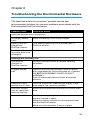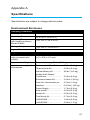
1
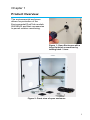
ENVIRONMENTAL DUSTTRAK™ ENVIRONMENTAL ENCLOSURE MODEL 854030 (FOR ENVIRONMENTAL DUSTTRAK™ AND DRX AEROSOL MONITOR MODELS 8540 AND 8543) OPERATION AND MAINTENANCE MANUAL P/N 6008410, REVISION A MAY 2015 Copyright© TSI Incorporated / 2015 / All rights reserved. Part Number 6008410 / Revision A / May 2015 Address TSI Incorporated / 500 Cardigan Road / Shoreview, MN 55126 / USA Fax No. (651) 490-3824 LIMITATION OF WARRANTY AND LIABILITY (effective February 2015) (For country-specific terms and conditions outside of the USA, please visit www.tsi.com.) Seller warrants the goods, excluding software sold hereunder, under normal use and service as described in the operator's manual, shall be free from defects in workmanship and material for twenty-four (24) months, or if less, the length of time specified in the operator's manual, from the date of shipment to the customer. This warranty period is inclusive of any statutory warranty. This limited warranty is subject to the following exclusions and exceptions: a. b. c. d. e. f. g. h. i. Hot-wire or hot-film sensors used with research anemometers, and certain other components when indicated in specifications, are warranted for 90 days from the date of shipment; DustTrak internal pump for Models 8530 and 8533 is warranted for two (2) years or 4000 hours, whichever comes first; DustTrak External pump for Models 8530EP and 8533EP is warranted for two (2) years or 8760 hours, whichever comes first: Environmental Dutra pump for Models 8540 and 8543 is warranted for two (2) years or 8760 hours, whichever comes first. Parts repaired or replaced as a result of repair services are warranted to be free from defects in workmanship and material, under normal use, for 90 days from the date of shipment; Seller does not provide any warranty on finished goods manufactured by others or on any fuses, batteries or other consumable materials. Only the original manufacturer's warranty applies; This warranty does not cover calibration requirements, and seller warrants only that the instrument or product is properly calibrated at the time of its manufacture. Instruments returned for calibration are not covered by this warranty; This warranty is VOID if the instrument is opened by anyone other than a factory authorized service center with the one exception where requirements set forth in the manual allow an operator to replace consumables or perform recommended cleaning; This warranty is VOID if the product has been misused, neglected, subjected to accidental or intentional damage, or is not properly installed, maintained, or cleaned according to the requirements of the manual. Unless specifically authorized in a separate writing by Seller, Seller makes no warranty with respect to, and shall have no liability in connection with, goods which are incorporated into other products or equipment, or which are modified by any person other than Seller. The foregoing is IN LIEU OF all other warranties and is subject to the LIMITATIONS stated herein. NO OTHER EXPRESS OR IMPLIED WARRANTY OF FITNESS FOR PARTICULAR PURPOSE OR MERCHANTABILITY IS MADE. WITH RESPECT TO SELLER’S BREACH OF THE IMPLIED WARRANTY AGAINST INFRINGEMENT, SAID WARRANTY IS LIMITED TO CLAIMS OF DIRECT INFRINGEMENT AND EXCLUDES CLAIMS OF CONTRIBUTORY OR INDUCED INFRINGEMENTS. BUYER’S EXCLUSIVE REMEDY SHALL BE THE RETURN OF THE PURCHASE PRICE DISCOUNTED FOR REASONABLE WEAR AND TEAR OR AT SELLER’S OPTION REPLACEMENT OF THE GOODS WITH NON-INFRINGING GOODS. i TO THE EXTENT PERMITTED BY LAW, THE EXCLUSIVE REMEDY OF THE USER OR BUYER, AND THE LIMIT OF SELLER'S LIABILITY FOR ANY AND ALL LOSSES, INJURIES, OR DAMAGES CONCERNING THE GOODS (INCLUDING CLAIMS BASED ON CONTRACT, NEGLIGENCE, TORT, STRICT LIABILITY OR OTHERWISE) SHALL BE THE RETURN OF GOODS TO SELLER AND THE REFUND OF THE PURCHASE PRICE, OR, AT THE OPTION OF SELLER, THE REPAIR OR REPLACEMENT OF THE GOODS. IN THE CASE OF SOFTWARE, SELLER WILL REPAIR OR REPLACE DEFECTIVE SOFTWARE OR IF UNABLE TO DO SO, WILL REFUND THE PURCHASE PRICE OF THE SOFTWARE. IN NO EVENT SHALL SELLER BE LIABLE FOR LOST PROFITS, BUSINESS INTERRUPTION, OR ANY SPECIAL, INDIRECT, CONSEQUENTIAL OR INCIDENTAL DAMAGES. SELLER SHALL NOT BE RESPONSIBLE FOR INSTALLATION, DISMANTLING OR REINSTALLATION COSTS OR CHARGES. No Action, regardless of form, may be brought against Seller more than 12 months after a cause of action has accrued. The goods returned under warranty to Seller's factory shall be at Buyer's risk of loss, and will be returned, if at all, at Seller's risk of loss. Buyer and all users are deemed to have accepted this LIMITATION OF WARRANTY AND LIABILITY, which contains the complete and exclusive limited warranty of Seller. This LIMITATION OF WARRANTY AND LIABILITY may not be amended, modified or its terms waived, except by writing signed by an Officer of Seller. Service Policy Knowing that inoperative or defective instruments are as detrimental to TSI as they are to our customers, our service policy is designed to give prompt attention to any problems. If any malfunction is discovered, please contact your nearest sales office or representative, or call TSI's Customer Service department at (800) 874-2811 (USA) or (001 651) 490-2811 (International) or visit www.tsi.com. Trademarks DustTrak™ and TrakPro™ are trademarks of TSI Incorporated. Netronix is a trademark of Netronix Inc. Velcro is a registered trademark of Velcro Industries B.V. ii Contents Contents............................................................................................. iii Safety Information ............................................................................. v Laser Safety ............................................................................................ vi Labels ..................................................................................................... vii Description of Caution/Warning Symbols ............................................... vii Caution and Warning Symbols .............................................................. viii Reusing and Recycling .......................................................................... viii Chapter 1 Product Overview ............................................................ 1 Chapter 2 Parts Identification and Unpacking ............................... 3 Parts Identification: Environmental Enclosure ......................................... 3 Unpacking the Model 854030 Environmental Enclosure ......................... 3 Model 854030 Environmental Enclosure Optional Accessories............... 5 Chapter 3 Setting Up ........................................................................ 9 Enclosure Assembly ................................................................................ 9 Tools Needed for Assembly..................................................................... 9 Equipment Needed for Maintenance ....................................................... 9 Overview ............................................................................................... 10 Cable Routing and Securing .................................................................. 10 Install Photometer.................................................................................. 11 Install the Padlock Adapter .................................................................... 11 Install the Door Vents and Screens ....................................................... 12 Install Handle Kit.................................................................................... 15 Solar Shield ........................................................................................... 16 Thiamis 1000 Node ............................................................................... 17 Configure Power Connection ................................................................. 17 DIN Rail and Phoenix Connectors ......................................................... 18 Mains Power Supply for Environmental DustTrak ................................. 19 Alternate DC Power Sources ................................................................. 22 Heated Inlet Accessory .......................................................................... 22 Enclosure Heater ................................................................................... 23 Install Photometer inside Environmental Enclosure ............................... 24 Assembly and Installation of Inlet Column ............................................. 25 Pole Mount Kit ....................................................................................... 28 Final Electrical Connection .................................................................... 28 iii Chapter 4 Operation........................................................................ 31 Overview ................................................................................................ 31 How to Properly Orient the Environmental Enclosure ............................ 31 Checklist for Sampling with the Environmental Enclosure ...................... 32 Transporting the Environmental Enclosure ............................................ 32 Removing Photometer from Environmental Enclosure ........................... 33 Chapter 5 Maintenance ................................................................... 35 Monthly Maintenance Checks ................................................................ 35 Cleaning the Aerosol Inlet ...................................................................... 35 Emptying the Water Trap ....................................................................... 36 Cleaning and Oiling Impactors ............................................................... 36 Chapter 6 Troubleshooting the Environmental Enclosure ......... 39 Appendix A Specifications ............................................................. 41 Environment Enclosure .......................................................................... 41 iv Safety Information WARNINGS The DustTrak™ 8540/8543 aerosol monitors are not rated for intrinsic safety. The DustTrak monitor, with the Environmental Enclosure, must never be operated under conditions where there is a risk of fire or explosion. Use of components other than those specified by TSI may impair the safety features provided by the equipment. The instrument has been design to be used with batteries supplied by TSI. Do not use a substitute. The TSI charger (P/N 801809) has been designed to be used with the battery packs supplied by TSI. Do not use a substitute charger to charge TSI battery packs. Old batteries must be properly recycled in accordance with the local environmental regulations. When mains power adapters are used, the equipment should be positioned so the mains plug will remain accessible for emergency disconnect. Do not use non-rechargeable batteries in this instrument. Fire, explosions, or other hazards may result. v Cautions The enclosure is designed to be water resistant to rain or spray. It has a NEMA rating of 3R and an ingress protection rating of IP44. It is not designed to be waterproof when immersed. Setting it in a pool of water will result in flooding the inner compartment with water. This will severely damage both your DustTrak II/DRX aerosol monitor and battery pack. Do NOT set the Environmental Enclosure in water! Any seal that is not properly installed could result in water intrusion inside the enclosure which can damage the instruments and batteries. Follow procedures outlined in this manual for proper installation and regular inspection of all seals. Note Prior to using the Battery Pack for the first time, a full recharge is recommended. Recharging Battery Pack(s) immediately after use (within one hour maximum) is critical to obtaining optimal recharge time, battery health, and battery life. Laser Safety The Model 8540/8543 DustTrak monitor is a Class I laser- based instrument During normal operation, you will not be exposed to laser radiation Precaution should be taken to avoid exposure to hazardous radiation in the form of intense, focused, visible light Exposure to this light may cause blindness Take these precautions: DO NOT remove any parts from the DustTrak monitor unless you are specifically told to do so in this manual. DO NOT remove the housing or covers. There are no serviceable components inside the housing. vi WARNING The use of controls, adjustments, or procedures other than those specified in this manual may result in exposure to hazardous optical radiation. W A R N I N G If the DustTrak monitor is used in a manner not specified by the manufacturer, the protection provided by the equipment may be impaired. When operated according to the manufacturer’s instruction, this device is a Class I laser product as defined by U.S. Department of Health and Human Services standards under the Radiation Control for Health and Safety Act of 1968. A certification and identification label like the one shown below is affixed to each instrument. Labels Advisory labels and identification labels are attached to the instrument. 1. European symbol for non-disposable item. Item must be recycled. Description of Caution/Warning Symbols Appropriate caution/warning statements are used throughout the manual and on the instrument that require you to take cautionary measures when working with the instrument. Caution Caution Failure to follow the procedures prescribed in this manual might result in irreparable equipment damage. Important information about the operation and maintenance of this instrument is included in this manual. vii Warning WARNING Warning means that unsafe use of the instrument could result in serious injury to you or cause damage to the instrument. Follow the procedures prescribed. Caution and Warning Symbols The following symbols may accompany cautions and warnings to indicate the nature and consequences of hazards: Warns that the instrument contains a laser and that important information about its safe operation and maintenance is included in the manual. Warns that the instrument is susceptible to electrostatic discharge (ESD) and ESD protection should be followed to avoid damage. Indicates the connector is connected to earth ground and cabinet ground. Reusing and Recycling As part of TSI Incorporated’s effort to have a minimal negative impact on the communities in which its products are manufactured and used: Do not dispose of used batteries in the trash. Follow local environmental requirements for battery recycling. If instrument becomes obsolete, return to TSI for disassembly and recycling. viii Chapter 1 Product Overview The environmental enclosure allows for protection of the Environmental DustTrak models 8540/8543 and their accessories to permit outdoor monitoring. Figure 1: Open Enclosure with a large flat head screwdriver by turning latch ¼ turn Figure 2: Front view of open enclosure 1 (This page intentionally left blank) 2 Chapter 1 Chapter 2 Parts Identification and Unpacking Carefully unpack the Model 854030 Environmental DustTrak™ Environmental Enclosure from the shipping container. Use the tables and illustrations below to make certain that there are no missing components. Contact TSI immediately if anything is missing or damaged. Parts Identification: Environmental Enclosure Identify the parts of the Model 854030 DustTrak Aerosol Monitor Environmental Enclosure (Error! Reference source not found. and Figure 4). Please become familiar with these components before proceeding. Unpacking the Model 854030 Environmental Enclosure Compare all the components you received with those listed in the table below. If any parts are missing, contact TSI. Item Qty Part Number Description 2 N/A Door Vents, screens, screws (4) 1 N/A Door Padlock pair 854035 Lift Handles for Enclosure 3 Item Qty Part Number Description Spare Parts available from suppliers by manufacturer part number listed below 4 www.phoenixcontact.com 4 www.phoenixcontact.com 3 www.phoenixcontact.com 5 Spring cage ground terminal block (Green) Power Connector Ground (Green) Large – P/N 3042733 (1) large – incoming power Small – P/N 304002 (3) small – power distribution Feed-through terminal block (Gray) Power Connector Supply (Gray) Large – P/N 3042719 (1) large – incoming power Small – P/N 3040012 (3) small – power distribution Plug-in Bridge Power Jumper Large, 22.7 mm x 9 mm, two-position P/N 3030161 (1) large – incoming power to distribution terminal blocks Small, 22.7 mm x 14.2 mm, three-position P/N 3030174 (2) small – to connect terminal block to terminal block Small plug Plug for 0.5” holes for handle bolts and wireless antenna Heyco® Nylon 0.5” dia Hole Plug, KOS LT 500 P/N 3830 https://octopart.com/ 1 Washer, ½ INT tooth lock 7/8 OD ZN Tooth lock washer to hold antenna plug in place 4 Large Plug Plug for 1.093” holes for power and communication connections ® https://octopart.com/ 4 Heyco -molded break-thru plug, 1.093” dia, LTGP 1093-063 P/N C2024 Chapter 2 Item Qty Part Number Description 2 Cable Gland Creates weatherproof seal for cable penetrations ® Heyco Series35 liquid tight cordgrips, LTF ¾, P/N 3234 https://octopart.com/ 2 Jam nut for cable gland Secures cable gland to enclosure. Heyco® Nylon Locknuts, NLN ¾ NPT P/N 8465 https://octopart.com/ 1 DC/DC CONVERTER 12V 30W Power to the DustTrak monitor Model 854030 Environmental Enclosure Optional Accessories Listed below are optional accessory items for the Model 854030 Environmental Enclosure. Contact TSI for purchase info. Item Parts Identification and Unpacking Part Number Description 854031 Pole Mount Kit for 854030 Enclosure 854032 Solar Shield for 854030 Enclosure 854033 Enclosure Heater for 854030 Enclosure 5 Item 6 Part Number Description 854034 Power supply for Environmental DustTrak 854041 Heated Inlet Sample Conditioner 801905 Thiamis 1000 GSM/GPS Node 854020 PM10 Impactor 854021 PM2.5 Impactor 854022 PM1.0 Impactor 854050 Lufft WS300 Metrology Station (Temp, Rh, air pressure) 854051 Lufft WS500 Metrology Station (Temp, Rh, air pressure, wind speed, wind direction) 854060 Solar Power System Chapter 2 Item Parts Identification and Unpacking Part Number Description 854036 Internal Battery System: Two (2) 22Ah Batteries* (801808), charger** (801809), plastic tray, and custom cable. 801808* 12 VDC Battery Pack* 801809** 12 VDC Battery Pack Charger 7 (This page intentionally left blank) 8 Chapter 2 Chapter 3 Setting Up The setup of the Environmental Enclosure is important to reliable and accurate sampling of aerosols in a wide range of conditions. TSI cannot ensure accurate measurements if any of the components are set up incorrectly. Failure to follow these procedures could result in damage to the enclosure or its components. Enclosure Assembly These assembly steps are organized to incorporate all available optional accessories at the time of assembly. Optional accessories can easily be added after assembly; however some components may need to be temporarily removed to facilitate installation and connection of some accessories. Tools Needed for Assembly (varies by accessory) Large flat-blade screwdriver Small flat-blade screwdriver Medium Phillips screwdriver 5 3 ½” wrench or socket 9 9 5 16” wrench 8” wrench 16” wrench 16” deep well socket 32” ball driver or Allen wrench Equipment Needed for Maintenance Compressed air or canned compressed air Teflon pipe tape 9 Overview The manual follows the order of the steps listed below with reference to applicable Quick Start Guides for optional accessories. 1. Start by opening door using large flat blade screw driver to turn latch ¼ turn. 2. Install padlock adaptors. 3. Install door vents and screens. 4. Install Thiamis Node antenna (use extender if solar shield will be installed). 5. Install handles and solar shield (optional accessories). 6. Install RH/Temp. Sensor if Heated Inlet Sample Conditioner module will be used (optional accessory). 7. Connect internal power supply connections (AC Power Supply, DC Power Connection Battery or Solar). 8. Connect heater, thermostat, and phoenix connector for Enclosure Heater (optional accessory) to DIN rail. 9. Install Thiamis Node on photometer service panel. 10. Install Heated Inlet Control Module (optional accessory) on photometer. Cable Routing and Securing Adhesive backed cable tie anchors are provided to help secure cables inside the enclosure. Securing cables to specific locations on the photometer and enclosure can prevent damage to cables during installation and removal of the photometer and help reduce confusion and mistakes during set up. Securing the cables to the enclosure is much easier to accomplish before the various accessories and photometer are mounted in the enclosure. Follow the Quick Start Guide steps included with the accessories for securing cables for any optional accessories to be used. 10 Chapter 3 Install Photometer 1. Insert photometer into enclosure and secure with retaining ring. 2. Build inlet column with Heated Inlet Sample Conditioner (optional accessory), impactors (optional choice), water trap, and 360° omni-directional inlet. 3. Thread Heated Inlet Cable (optional accessory) through opening in connector ring. 4. Place inlet column on top of photometer ring and rotate until alignment pin engages. Tighten down column ring to secure inlet column to photometer. 5. Connect cables for Photometer, Netronix Node, and any optional accessories (Heated Inlet, Enclosure Heater) as directed in the Quick Start Guides. 6. Connect batteries or connect to external power source. Install the Padlock Adapter The Padlock adapter allows for the case to be locked. The following steps describe how to install the Padlock Adapter. Tools needed: 1 8” Ball Driver or Allen wrench 3 8” Wrench Figure 3: Door Padlock 1. Place the Padlock adapter on the front door and push the mounting screws through the pre-drilled holes as shown in Figure 4. Figure 4: Mount Padlock Adapter Setting Up 11 2. Secure the Padlock adapter to the door using washers and screws as shown in Figure 5. Sealing surface on washers face enclosure. #10 Screws Sealing washer Lock nut Figure 5: Secure Padlock Adapter Install the Door Vents and Screens Install the Vents and Screens to the front door. Retainer Ring Vent Screen and Frame Figure 6: Install Door Vents and Screens Tools needed: Phillips screwdriver 12 Chapter 3 1. Remove retainer ring from back of vent assembly. Push the vent through the front door in two places with opening oriented down (as shown in Figure 7) and O-ring on the outside of the enclosure (not shown). When properly installed, the O-ring will cause a slight gap between the vent and the enclosure door. The O-ring provides the weather proof seal. 2. Attach retainer ring to vent cover thread by twisting with hand. Figure 7: Place vent cover through front door, twist retainer ring into place Setting Up 13 3. Orientate frame to ensure screen is held in place against the retainer ring. 4. Using a Phillips head screwdriver, attach screen and frame to retainer ring. Figure 8: Attach filter screen to retainer ring 14 Chapter 3 Install Handle Kit 1. Remove the ½” plugs (qty. 4) included with the 854030 enclosure. Figure 9: Install handle kit 2. Remove the star washer included with the handles. Figure 10: Remove star washers 3. Position the 38” washers on the exterior of the enclosure. Install the sealing washers on the interior with the rubber side of the sealing washer facing the enclosure surface. Figure 11: Position washers Setting Up 15 4. Handles install through the same holes with the same hardware used to attach the solar shield. The optional Solar Shield (854032) can be installed at the same time the handles are installed. Figure 12: Install optional solar shield (854032) Refer to the Quick Start Guides supplied with the optional accessories for installation instructions: Solar Shield (optional accessory P/N 854032) See Quick Start Guide 6008675 included with accessory. Figure 13: Solar shield (854032) 16 Chapter 3 Thiamis 1000 Node (optional accessory P/N 801905) See Quick Start Guide 6008413 included with accessory. Figure 14: Thiamis 1000 Node (801905) Configure Power Connection The 8540/8543 Environmental DustTrak may be powered with: 1. AC mains power (part number 854034) 2. Battery Pack Kit (part number 854036) 3. DC input for Solar Power (part number 854060). The power connections and set up within the enclosure are much easier to manage before the photometer is installed. External connection to the power supply should not occur until the photometer and associated accessories are connected inside the enclosure. Note The power supply included with the Enclosure Heater Accessory (P/N 854033) requires AC Mains Power. Setting Up 17 DIN Rail and Phoenix Connectors Power supplied to the Instruments is fed through an assembly of Phoenix Connectors snapped onto the DIN rail. Additional Phoenix Connectors can be purchased directly from www.phoenixcontact.com. Green connectors are the “DC ground” connection. Gray connectors are the “positive DC voltage” connection. The pair of larger connectors (size 4) on the far left bring power into the DIN rail from Main Line Power, Batteries, Solar Power System, or Wind Power system. The smaller pairs of connectors (size 2.5) are used to supply power to various instruments in the enclosure. Additional connectors can be added to power additional instruments as needed. The red plug-in bridge clips distribute power from a Gray connector to the adjacent or the next Gray connector. Note the different sizes of red jumper clips. Notes: Larger red jumper (with center tang removed) distributes power to the next connector. Incoming Power Power Distribution Small red jumper distributes Incoming power to adjacent distribution connector. Figure 15: DIN rail and Phoenix connectors 18 Chapter 3 Replacement connectors can be purchased directly from the manufacturer as follows: www.phoenixcontact.com Connector Part Number Adjacent jumper (to distribute power from large gray connector to adjacent small gray connector) 3030161 Regular jumper (to distribute power from a small gray connector to another small gray connector) 3030174 Large, Incoming Power Connector: Green (DC ground) 3042722 Gray (positive DC voltage) 3042719 Small, Distribution Power Connectors: Green (DC Ground) 3040025 Gray (positive DC voltage) 3040012 Mains Power Supply for Environmental DustTrak (optional accessory P/N 854034) See Quick Start Guide 6008574 included with Power Supply. Attach mains power cable to power supply and attach to power rail. Connect DC Power Cable to DIN DC Input. Figure 16: Mains power supply (854034) Setting Up 19 WARNING When mains power adapters are used, the equipment should be positioned so the mains plug will remain accessible for emergency disconnect. Environmental DustTrak Battery Kit (Optional Accessory P/N 854036) See Quick Start Guide 6008712 included with accessory The internal battery system consists of two rechargeable lead acid batteries with a specially designed charger. A wiring harness draws power from both batteries, doubling the run time. No connection through the outside of the enclosure is required for using the internal battery system. There is a 5.0AT 5x20mm fuse built in to the cable. Figure 17: Battery kit (854036) 20 Chapter 3 Notes To integrate the battery into the environmental enclosure, the battery will need to be purchased as an optional accessory. Part number 854036 includes: two (2) 22Ahr batteries; battery charger, battery tray, and dual wiring harness. Additional battery (part number 801808). Additional battery charger (part number 801809) Prior to using the Battery Pack for the first time, a full recharge is recommended. Recharging Battery Pack(s) immediately after use (within one hour maximum) is critical to obtaining optimal recharge time, battery health, and battery life. Use of components other than those specified by TSI may impair the safety features provided by the equipment. WARNING The instrument has been design to be used with batteries supplied by TSI. Do not use a substitute. The TSI charger (P/N 801809) has been designed to be used with the battery packs supplied by TSI. Do not use a substitute charger to charge TSI battery packs. Old batteries must be properly recycled in accordance with the local environmental regulations. Setting Up 21 Alternate DC Power Sources Solar Power System for Environmental DustTrak (optional accessory P/N 854060) See Quick Start Guide 6008416 included with accessory. Figure 18: Solar power system (854060) Heated Inlet Accessory (optional accessory P/N 854041) See Quick Start Guide 6008577 included with accessory. Heated Inlet Column Cable Gland RH/Temp Sensor Control Board Figure 19: Heated inlet accessory (854041) 22 Chapter 3 Enclosure Heater (optional accessory 854033) See Quick Start Guide 6008412 included with accessory. Laser Power Supply Thermostat Controller Heater Phoenix Connectors Figure 20: Enclosure Heater (854033) WARNING Ensure AC cable and all communication cables are routed away from direct contact with the heater module to prevent shorting and damage due to potential melted cable insulation. Setting Up 23 Install Photometer inside Environmental Enclosure 1. Remove the Mounting Ring from bottom of inlet column and attach to top of photometer using four (4) screws provided. Note: Ensure keyhole opening is orientated to the front of the photometer. 2. Add O-ring to mounting ring attached to photometer. 3. Lift photometer up through enclosure, guiding the attached mounting ring through the opening. 4. Place plastic glide ring around mounting ring protruding through top of enclosure. 5. Use the retainer ring to secure the photometer to the enclosure. Hand-tighten retainer ring to mounting ring. Do not use tools for additional leverage. Retainer Ring (threaded end up) Plastic Glide Ring O-Ring Mounting Ring (keyhole orientated forward) Figure 21: Install DustTrak Monitor – insert inlet ring up through opening WARNINGS 24 Retainer ring and O-ring must be properly orientated to ensure a good seal to prevent water leakage. Care must be taken to hold the photometer while tightening or loosening the retaining ring to prevent damage to the photometer from an unexpected drop. Chapter 3 Assembly and Installation of Inlet Column 360 Inlet Mounting Ring Water Bottle Retainer Ring (secures DustTrak to Enclosure) Plastic Spacer and O-ring Column Retainer Ring (secures inlet column to DustTrak mounting ring) Inlet Base Figure 22: Inlet column parts 1. Build inlet column starting from the bottom with the Inlet base or Heated Inlet sample conditioning module (optional accessory). 2. Set inlet column on top of mounted photometer, rotate slowly until alignment pin drops column into proper orientation. 3. Hand-tighten base retainer ring to secure inlet column to enclosure. 4. Slide retainer ring down to inlet base or optional heated inlet column. Base Retainer Ring Inlet Base O-ring Retainer Ring Plastic Glide Ring Figure 23: Assembly and installation of inlet column Setting Up 25 5. Add any optional size selective impactors (not shown). See Quick Start Guide 6008674 Installing Impactor onto the Omnidirectional inlet. Figure 24: Assembly and installation of inlet column 6. Add the water trap. 7. Add the 360° omni-directional inlet. WARNING Inspect all O-rings for damage and contamination during installation to ensure a good seal to prevent water leakage. 360° inlet and water trap. Inlet Base or Heated Inlet Sample Conditioner (optional accessory 854041) Figure 25: Final configurations of inlet column 26 Chapter 3 After water trap is threaded into inlet column, unscrew glass jar by hand to empty and replace. Size selective impactors insert here. Figure 26: Removal of glass jar from flow stack WARNING Care must be taken when attaching or removing the omni-directional inlet column from the enclosure and/or photometer to prevent breaking the glass water trap jar due to mishandling or dropping the column. Setting Up 27 Pole Mount Kit (optional accessory 854031) See Quick Guide 6008411 included with accessory. Figure 27: Pole mount kit (854031) Final Electrical Connection After completing all internal connections from the Instrument and accessories to the DIN Rail, make final connection of DustTrak power connector to DIN Rail mounted power supply. Then plug external power cord into enclosure connection. Figure 28: DustTrak Power Connection (left). Final connection to exterior AC power source (DC power source will use 2-pin connector on left side of enclosure – right) 28 Chapter 3 Line cord plug l must be connected to electrical power inside a water resistant/waterproof outdoor receptacle enclosure. Figure 29: Water resistant / waterproof outdoor receptacle enclosure Check instruments to verify power is working before closing and locking enclosure. WARNING Improper outdoor installation could result in equipment damage and/or electrical shock due to improper grounding. Installation must follow local electrical codes. Electrical connections should be completed by a licensed electrician. Setting Up 29 (This page intentionally left blank) 30 Chapter 3 Chapter 4 Operation Overview The Environmental Enclosure can be used in conjunction with the 8540 or 8543 Environmental DustTrak aerosol monitor for many different applications. Its primary use is in outdoor applications to give the DustTrak monitor protection from the elements and the ability to sample efficiently in different wind speeds. How to Properly Orient the Environmental Enclosure Set up the Environmental Enclosure in a location where it can sample the particles of interest. It should be placed “out in the open,” away from obstructions which may affect wind currents. For example, do not place it at the corner of a building, which would cause swirling wind currents and result in poor particle sampling. Use the Environmental Enclosure in wind conditions with speeds of 22 mph or less to obtain the most accurate readings. An increase in wind speed over 22 mph can decrease the sampling efficiency of the inlet to under the efficiency specified by PM-10 standards. If wind gusts of over 22 mph are present, the data collected is still valid, but be aware that the readings will be slightly lower than the actual mass concentration of aerosol present. If the Environmental Enclosure is exposed to direct sunlight, causing the temperature inside to approach the operating limit of 50°C, the Solar Shield should be used. The Solar Shield blocks the direct sunlight, keeping the temperature inside the Environmental Enclosure cooler than it would otherwise be. Orient the Environmental Enclosure with Solar Shield such that the Solar Shield faces the sun directly when the sun is at its highest point in the sky. This will maximize the effectiveness of the Solar Shield. 31 Checklist for Sampling with the Environmental Enclosure Before beginning a sample, check to see that all of the following conditions are satisfied: All components are properly installed into the enclosure as described in the Setup section. The Environmental DustTrak monitor (8540/8543) has been zeroed at the temperature at which it will be sampling (if possible). The Environmental Enclosure has been put in a place clear of any obstructions that will affect the flow around the enclosure. The Enclosure is not resting directly on the ground (no standing water). The Environmental DustTrak monitor (8540/8543) has been set to the appropriate survey or logging mode. The Enclosure is locked shut to prevent theft or vandalism to instrument. Transporting the Environmental Enclosure When transporting the Environmental Enclosure it is important to store its components correctly. To ensure that no damage is done to the enclosure or its components during transportation, the following steps should be taken: Attention The Environmental Enclosure is designed to protect equipment during stationary sampling only. Do not transport or ship equipment inside the Environmental Enclosure. 1. Unscrew the aerosol inlet from the top of the case. 2. Empty any water from the water trap. 3. Remove antenna and extender for GSM/GPS modem accessory if in use. 4. Remove RH/Temp sensor for heated inlet accessory (if applicable). 5. Remove Environmental DustTrak aerosol monitor. 6. Remove batteries (if applicable). 32 Chapter 4 7. Remove power supply (if applicable). 8. Remove Enclosure Heater (if applicable). 9. Package enclosure to prevent damage. 10. Package accessories to prevent damage. Removing Photometer from Environmental Enclosure When the photometer is removed from the enclosure, the top of the enclosure will have an opening unless the inlet is reinstalled. Follow the steps below to install the column to the mounting ring from the DustTrak monitor to ensure a waterproof seal on the enclosure. WARNING Disconnect all cables before removing photometer from Environmental Enclosure to prevent damage. 1. Remove the mounting ring from the photometer. Save the screws for reinstallation. Figure 30: Remove mounting ring from photometer 33 2. Hold Mounting Ring in opening inside enclosure and secure with retainer ring on top of enclosure. Figure 31: Secure retainer ring WARNINGS Retainer ring and O-ring must be properly orientated to ensure a good seal to prevent water leakage. Inspect all O-rings for damage and contamination during installation to ensure a good seal to prevent water leakage. 3. Place inlet column into place, turning until pin fit into hole. 4. Twist Base Retainer Ring to secure inlet column to Retainer Ring in enclosure. Figure 32: Secure inlet column to retainer ring 34 Chapter 4 Chapter 5 Maintenance Monthly Maintenance Checks No te: Extreme conditions may require more frequent maintenance. 1. Check the gasket around the door for proper seal. 2. Check the door vents for tightness and filters in place. 3. Ensure the photometer is secured to the enclosure with the retainer ring. 4. Ensure the Omni-directional inlet column is secured to the photometer by the base retainer ring. 5. Empty the water trap if needed. 6. Open the impactor (if used) clean and re-oil the impactor. 7. Ensure all cable grommets and hole plugs through environmental enclosure are snug and weather tight. 8. Ensure all internal wiring and cable routing tie wraps are properly secured to the enclosure. 9. Inspect internal wiring and cables for loose connections and damaged wires and cables. 10. Ensure wires and cables are not routed on top of heater at risk of melting (if used). 11. Ensure enclosure is securely mounted to Pole Mounting Kit or other fixture and any attachment point. 12. Ensure enclosure is securely locked to prevent theft. Cleaning the Aerosol Inlet Under normal operating conditions, the external aerosol inlet will remain clean and unobstructed. Under very dirty conditions; however, the inlet may become obstructed with vegetative debris or insects. To ensure the inside of the aerosol inlet is clean, periodically remove 35 omni-directional inlet and blow compressed air through the bottom of the inlet. Caution Do not disassemble the Environmental Enclosure aerosol inlet for any reason. It is not designed for field service and reassembly. Emptying the Water Trap If any water or moisture has accumulated in the water trap, unscrew the water trap from the omni-directional inlet and empty it. The bottle must be securely hand tightened to seal against the O-ring to prevent leaking. Make sure the tightly secured bottle is oriented in the position shown in Figure 33. If water trap top is removed from fitting, re-apply Teflon pipe tape to fitting before installing cap to ensure a good seal is maintained. Teflon Pipe Tape Figure 33: Water trap orientation on inlet column Cleaning and Oiling Impactors The PM2.5 impactor is used to perform a Standard Calibration (size correction) on the Environmental DustTrak DRX instrument, as described in the Operations section of the Photometer manual. The calibration impactor should be cleaned prior to every use as follows. Follow recommended impactor cleaning interval for size selective impactors used with model 8540 Environmental DustTrak instrument. 36 Chapter 5 1. Unscrew Impactor. Check O-ring on the impactor base. 2. Clean outside and inside of Impactor and the impactor plate using a clean brush and a light solvent. Dry impactor parts by blowing it out with compressed air, or let it air-dry thoroughly. 3. Apply two drops of oil (included) to the impactor plate. Do not over-fill impaction plate. Apply 2 Drops of Oil Figure 34: Apply 2 Drops of Oil to Impactor Plate 4. Screw (hand-tighten) impactor back together. Maintenance 37 (This page intentionally left blank) 38 Chapter 5 Chapter 6 Troubleshooting the Environmental Enclosure The table below lists the symptoms, possible causes and recommended solutions for common problems encountered with the Environmental DustTrak Enclosure. Possible Cause Corrective Action DustTrak monitor does not turn on. Uncharged Battery Pack. Make sure Battery Pack is fully charged. Battery Pack not plugged into DustTrak monitor. Plug battery power plug into the power jack in DustTrak monitor. Bad Battery Pack (no longer able to be recharged). Replace with new Battery Pack. Readings are unusually low. Zero was not checked on DustTrak monitor. Re-zero DustTrak monitor at desired sampling conditions. Plugged external inlet. Remove inlet from the Enclosure; blow out debris with compressed air. Rinse with clean air, if needed. DO NOT DISASSEMBLE COVER ON INLET ASSEMBLY. Take off water trap bottle and clean all exposed surfaces. Sampling in wind speeds over 22 mph. DustTrak monitor will under-sample slightly in high wind speeds. No correction possible. Enclosure located near an object that obstructs the flow. Move the Environmental Enclosure into a more open area. Leak in the inlet. Make sure the upper inlet assembly and the water trap are screwed in tightly. Make sure tubing is secured on the enclosure barb and the DustTrak monitor. Make sure inlet assembly O-ring is in place. 39 (This page intentionally left blank) 40 Chapter 6 Appendix A Specifications Specifications are subject to change without notice. Environment Enclosure Sampling Conditions Wind Speed 0 to 22 mph (0 to 36 kph) Operating Temperature 32 to 120F (0 to 50C) Operating Temperature with Heater accessory Model 854034 -4 to 120F (-20 to 50C) Storage Temperature -4 to 140F (–20 to 60C) Ingress Protection IP44 Physical External dimensions with no sample inlet (HWD) 16 x 12 x 12.25 in. (411 x 305 x 311 mm) Approximate Weight Enclosure (empty) 20 lbs (9.07 kg) Approximate weight of accessories Environmental DustTrak...... 5.3 lbs (2.4 kg) Thiamis Node Kit ................. 0.8 lbs (0.4 kg) Internal Battery Kit .............. 30 lbs (13.6 kg) Heated Inlet Sample Conditioner.......................... 2.0 lbs (0.9 kg) Enclosure Heater Kit ........... 3.4 lbs (1.54 kg) Omni-dir. inlet w/water jar ... 2.2 lbs (1.0 kg) Impactor .............................. 0.23 lbs (.105 kg) Power Supply ...................... 1.7 lbs (0.8 kg) Solar shield ......................... 2.0 lbs (0.9 kg) Handle kit ............................ 0.6 lbs (0.3 kg) Pole Mount Kit..................... 6.7 lbs (3.0 kg) Lufft WS300 ........................ 1.8 lbs (0.8 kg) Lufft WS500 ........................ 2.9 lbs (1.3 kg) 41 Maintenance Requirement Maintenance Check/ Clean omnidirectional inlet Average Dust Concentrations 35 ug/m3 50 ug/m3 100 ug/m3 42 days 30 days 16 days Internal Battery System Internal Battery Pack 12 VDC, 22 Ah Battery Run-time Environmental DustTrak/DRX monitor: Single battery ......................21 to 24 hours (typical) Dual batteries .....................42 to 48 hours (typical) Environmental DustTrak/DRX monitor: With heated inlet accessory: Single Battery .....................15 hours (typical) Dual Batteries .....................30 hours (typical) Battery Charge Time 8 to 9 hours at 72F (22C) (New battery, deep discharge to 95% charge) AC and DC Power Requirements AC Power 100 to 240 VAC, 50/60 Hz, 120 W Maximum (300 W Max for power supply included with Enclosure Heater) DC Power (solar option) 12 VDC, 50 W Maximum 42 Appendix A TSI Incorporated – Visit our website www.tsi.com for more information. USA UK France Germany Tel: +1 800 874 2811 Tel: +44 149 4 459200 Tel: +33 1 41 19 21 99 Tel: +49 241 523030 P/N 6008410 Rev. A India Tel: +91 80 67877200 China Tel: +86 10 8219 7688 Singapore Tel: +65 6595 6388 ©2015 TSI Incorporated Printed in U.S.A.