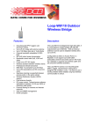
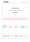
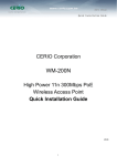
1
ENGLISH
UHF RFID Reader
2.4 GHz Uni-directional Reader
BG-245/W
BGC-04
BGC-K
BGC-S
Table of Contents:
1. Overview …………………………………………………………………………. 1
1.1 LED status of the BG-245/W UHF RFID Reader
1.2 Audio Signal of the BG-245/W UHF RFID Reader
2. Connecting your 2.4G UHF RFID System ……………………………………... 2
2.1 Wire Definitions
2.2 Adjust Reading Ranges
2.3 Upload Data Filter
2.4 Networking your 2.4G UHF RFID System
3. Example: Installation for Automatic Vehicle Identification …………………..3
4. Repair and Maintenance ……...……………………………………………….... 3
4.1 Top Tips to Keep the Device Working
4.2 Troubleshooting
5. Battery Replacement Instructions for Tags ……………………………………. 4
5.1 BGC-03 Battery Change Procedures
5.2 BGC-K Battery Change Procedures
5.3 BGC-S Battery Change Procedures
Reference: BG-245/W Reader Specifications. …………………………………... 10
Chart: BG-245/W Reader Specifications
Document: BG-245 UHF Reader Physical Installation Instruction.pdf
1. Overview
2.4G Hz long distance reading system employs the ISM microwave. The reflection of
radio waves can be helpful in transmitting a radio signal over long distances in high
speed. Active RFID tags have their own internal power source, which is used to power
the integrated circuits and broadcast the signal to the reader. If the reader has received
the signal from tag, the reader will send the data to the server computer for data
processing.
1.1 LED status of the BG-245/W UHF RFID Reader
Green LED: Flashing once per second: the reader is working properly.
Red LED: Flashing once per 2 seconds: a tag has been read.
1.2 Audio Signal of the BG-245/W UHF RFID Reader
1 beep: a new tag has been read by the reader.
Note: when a tag has been read once, if it remains in its reading distance, the tag will
not trigger the buzzer again; if the tag is moved beyond its reading distance and then
moved within its reading distance later on, the reader considers it is a new tag and will
emit 1 beep.
2. Connecting your 2.4G UHF RFID System
2.1 Wire Definitions
The 6-core wire for external connection has the following color in sequences: red,
black, white, green, yellow, and blue. The red and black wires are for power source.
When the power source is DC, the black wire is ground wire; when the power source
is AC, there is no sequence for the red and black wires.
BG-245/W Reader Wire Definitions
Color
Red
Black
White
Green
Blue
Yellow
Definition
Power (+)
Power (-) / GND
Control Signal Input
Control Signal Input (GND)
Wiegand Output DATA 1
Wiegand Output DATA 0
-1-
Notes:
a. The black wire of the BG-245/W must connect with the GND port of the
Wiegand controller; otherwise, the reader would not upload data to the controller.
b. By default, the white wire and green lines are welded together to enable the reader
to read tag.
c. To enable reader to work in a trigger mode, i.e. begin to read only when a car
arrives, user can set apart the white and green lines, and connects them separately to
the N/O and COMMON ports of the same channel in a loop detector.
2.2 Adjust Reading Ranges
The reading range is adjustable from 1 to 170 meters and depends on the types of tags.
This can be done by adjusting the potentiometer at the bottom of the antenna (refer to
the picture).
Potentiometer
2.3 Upload Data Filter
Encoder
By default, BG-245/w reader should transfer every tag ID immediately once it reads a
tag. In some cases the system needs to avoid repeated tag IDs, so as to ensure the
operation of the system. BG-245/w can be set to meet the requirements.
There is an embedded encoder in the bottom of the reader. Clients can shift the
decoder to define a specific interval, so that within the interval the reader would only
transfer unique tag IDs they read.
The encoder provides ten options of intervals. Standard options are from the shortest
0.8s, to the longest 70s. Details of the options are as below:
Option
Interval
0
0.8S
1
5S
2
10S
3
15S
-2-
4
20S
5
30S
6
40S
7
50S
8
60S
9
70S
2.4 Networking your 2.4G UHF RFID System
Wiegand Controller
3. Example: Installation for Automatic Vehicle Identification
Automatic vehicle identification, e.g. parking access control is a major application of
Bluecard’s BG-245 reader. You may refer to the following steps to install our
products to benefit such systems.
1. Dispatches 2.4GHz active RFID tags to car owners/drivers. Each tag has a unique
ID no., which can be associated with certain information of the tag holder such as the
vehicle number, driver’s age and contacts, etc., which are stored in the server
computer.
2. Connects the BG-245/w reader to wiegand controller. (Since the power supply is
8~20V DC, please use an appropriate adaptor or wiegand controller as a power
source.)
3. Adjusts the potentiometer in the BG-245/w readers to get an appropriate reading
distance.
4. Installs BG-245/w readers to poles or walls following the BG-245 UHF Reader
Physical Installation Instruction.pdf.
-3-
After the installation and configuration processes, the readers would automatically
detect active tags held by the car owner, and upload tag IDs to the Wiegand controller
immediately.
4. Repair and Maintenance
4.1 Top Tips to Keep the Device Working
1. Do not sabotage the 2.4G active tag by beating it or having a strong impact on it.
2. Do not disassemble the 2.4G tag, unless for changing batteries following the
procedures as instructed in this manual.
3. Once a reader has been fixed, please do not to move its position unless it is
malfunctioned. Otherwise the stability of the whole system could be affected.
4. As to BGC-01/BGC-03 tag, the labels on the tags help to protect the tags against
water or moisture, please do not tear them down unless for battery changing.
4.2 Troubleshooting
1) If the reader is powered on (the green LED is on and flashing), but does not read
tags (the green LED never switches to the Red LED, and there is no beep sound from
the buzzer), please check and make sure the green wire has been connected to the
white wire.
2) If the reader works properly, but the controller could receive no data, please check
the wiring sequence of the yellow and the blue wires to the wiegand ports. If the
sequence were wrong, please cut off the power supply and then swap the yellow and
blue wires to the correct connection.
5. Battery Replacement Instructions for Tags
5.1 BGC-03 Battery Change Procedures
-4-
Step 1: Lift up the cover sticker by using the tweezers.
Step 2: Remove the cover sticker (spare cover stickers for each tag will be supplied).
Step 3:
Lift up the battery by using a non-conductive stick (e.g. a plastic stick).
-5-
Step 4: Take out the battery.
Step 5: Put back with a new battery and a new cover sticker.
5.2 BGC-K Battery Change Procedures
Step 1: Remove the screws by using a proper screwdriver.
Step 2: Open the covers of the card.
-6-
Step 3: Remove the battery from the battery case.
Step 4: Put back with a new battery and reassemble the covers.
5.3 BGC-S Battery Change Procedures
Step 1: Place a card on the table with the no label side face-up.
Step 2: Insert a tweezer to the narrow groove at the right bottom of the card, and push
-7-
the groove slightly (in a direction as shown by the arrow in the picture), so that the
battery case can pop out.
Step 3: Take out of the battery case completely, and replace the batteries. Please note
that the positive terminal of the battery should face towards the no label side of the tag.
Step 4: Insert the batteries (with the case) back from the left bottom of the tag, and
then push the right end of the battery case to reassemble it.
-8-
Reference:
Chart: BG-245/W Reader Specifications
Dimension
220mm×220mm×40mm
Weight
1500g
Tag Recognize Speed
150 Km/h
Power Supply
8 ~ 20V DC
Antenna Gain
8dBi
Antenna Horizontal Beamwidth 120°
Antenna Vertical Beamwidth
90°
Modulation
GFSK
Communication Port
Wiegand (26/34), factory defined
Reading Range
Uni-directional
Reading Distance
1-170M adjustable, and depending on tags
Tag Recognize Speed
200 tags in 4 seconds
Operating Temperature
-20℃~+70℃
Storage Temperature
-40℃~+85℃
Document: BG-245 UHF Reader Physical Installation Instruction.pdf
-9-