1
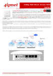
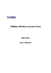
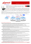
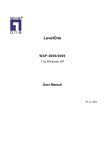
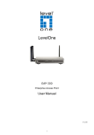
User’s Manual Quick Installation Guide CERIO Corporation WM-200N High Power 11n 300Mbps PoE Wireless Access Point Quick Installation Guide V2.0 1 User’s Manual Quick Installation Guide Introduction Overview Aspiring to provide the best performance/price ratio for both SMB and industrial applications, CERIO WM-200N is uniquely designed for Wall Mount with metal case and IP50 rating for a fast, robust, secure and business class access point perfect for installation in factories, warehouses, hotels marinas, hospitals, large homes, hotspot and more. CERIO WM-200N is compliant to the latest wireless standards that are required in highly secured enterprise networking environments. Its Wireless Distribution System (WDS) feature allows for flexible extension of wireless coverage. It can be power via three alternative methods from either the Single LAN port for Power over Ethernet (PoE), DC jack providing the ability to back up each other with fail-over redundancy function, giving WM-200N reliable connectivity in mission critical situations. The antenna diversity design enhances the connection reliability to improve data transmission capability. WM-200N High Power AP Support to pure output power to 300mW and has two detachable 8dBi high-gain antennas for optimal wireless coverage. CERIO WM-200N is easy-to-use and install with web-based administrative interface making configuration and client management simple and easy. In addition, management interfaces such as CLI and SNMP are also supported by WM-200N Support Multiple-SSID capability is to use just one AP to simultaneously emulate up to 8 APs with different ESSIDs by separate their packets by using different VLAN IDs. Hence, using one AP is able to act as if there are actually 8 different APs deployed in the same area. Client isolation is also supported by WM-200N that clients under an AP are isolated with each other. Package Contents WM-200N (main unit) Power Adapter 8dBi Dipole SMA Omin Antenna Ground Cable RJ-45 Ethernet Cable Mounting Screw pack Rubber Gasket Warranty Card CD Manual x1 x1 x2 x1 x1 x1 x1 x1 x1 2 User’s Manual Quick Installation Guide Features Key Feature 300mW Pure Output Power for 11n Mode , Provide best WiFi coverage Operation Modes : Access Point, WDS (Repeater) Maxmum Security with 802.1x, WPA, and AES Integragted IEEE 802.3af Power over Ethernet (PoE) Dual PoE Power redundancy Include High Gain 8 dBi detachable antenna for optimal wireless coverage. Support 8 Multiple-BSSIDs. Enclosed in an IP50 compliant metal chassis . Access Point Feature Number of ESSID: 8. Number of associated clients per ESSID: 32. WDS Mode support to extend wireless coverage by connecting wirelessly to another WDS capable AP up to 8 WDS links. Beacon interval: adjustable to best adapt to the deployment environment. IAPP: to facilitate faster roaming for the stations among different APs nearby. Support Adjustable transmission power: 7 Levels. Support Tag VLAN function. Authentication/Encryption (Wireless Security) WEP (64/128/152-bits) , WPA/WPA2 with TKIP or AES-CCMP, IEEE802.1X,WPA-PSK, WPA-Enterprise. Setting for TKIP/CCMP/AES key’s refreshing period Hidden SSID broadcast support. Access Control list (ACL) by MAC Address. Support WEP and AES data encryption over WDS link. Management Support SNMP V2c, V3 Web-Based management interface. Upgradeable firmware. Software one-button-click to reset back to factory defaults. Configuration backup & restore. Support use Static IP and DHCP client. Support Event log. 3 User’s Manual Quick Installation Guide Panel Function Description There are several LED indicators and button on the front of the WM-200N. Please refer to the definitons below : Front Panel Real Panel LED Panel 4 User’s Manual Quick Installation Guide 1. 12V DC Injector : Attach the power cable here. 2. Reset Button ( Reboot ) :Press and hold the Reset button for 2 seconds to restart system. The LED except Power indicator ( this button only for quickly Reboot ) 3. LAN1(PoE)/ LAN2/ LAN3 :The LAN1/LAN2 /LAN3 port are for connection to external network or POE switch. 4. Console : The Serial RS-232 DB9 cable attaches here. 5. Scan Button : → Press and hold the Reset button for 3 seconds and release to Scan New AP's Channel. The STATUS LED will be FLASH → Press and hold the Reset button for more than 10 seconds to reset the system to default configurations. The SYSTEM LED will be FLASH ( Reset factory default ) 6. Antenna : WM-200N supports 1 RF Interface with 2 SMA connectors for Antenna connection. 7. STATUS: LED ON indicates System up, OFF indicates down, FLASH indicates Scan button activated. 8. SYSTEM: LED ON indicates Flash busy, OFF indicates Flash Idle 9. WLAN : Green LED FLASH indicates Wireless ON, and FLASH quickly indicates Wireless Transmit quickly. 10.LAN1/LAN2 /LAN3: Green LED ON indicates connection, OFF indicates no connection, and FLASH indicates The Port Transmit 11.PWR : Green LED ON indicates power on, and OFF indicates power off. 5 User’s Manual Quick Installation Guide First-Time Installation and Configuration This chapter describes how to setup your WM-200N eXtreme PoE High-End Wireless Access Point for wireless connectivity to your LAN. Please Follow below setup 1. Place the WM-200N at a best location. The best location for WM-200N is usually at the center of your wireless network. 2. Connect WM-200N to your external network device. Connect one end of the Ethernet cable to the LAN1 port of WM-200N on the front panel. On your environment, connect the other end of the cable to the external Internet. The LAN1 LED indicator should be ON to indicate a proper connection. 3. Connect WM-200N to your network device. Connect one end of the Ethernet cable the LAN2 port of WM-200N on the front panel. Connect the other end of cable to a PC for configuring the system. The LAN2 LED indicator should be ON to indicate a proper connection. 4. There are two ways to supply power over to WM-200N I. Connect the DC power adapter to the WM-200N power socket one the front panel. Please only use the power adapter supplied with the WM-200N package. Using a different Power adapter may damage this system II.WM-200N is capable of transmitting DC current via its LAN PoE port. Connect an IEEE802.3af-compliant PSE device, e.g. A PoE Switch, to the LAN1 port of WM-200N with the Ethernet cable. Now, the hardware installation is completed. Software Configuration WM-200N supports web-based configuration. Upon the completion of hardware installation, WM-200N can be configured through a PC/NB by using its web browser such as Internet Explorer 6.0 or later. Default IP Address: 192.168.2.254 Default Subnet Mask: 255.255.255.0 6 User’s Manual Quick Installation Guide Default Username and Password for “root”: root / default IP Segment Set-up for Administrator's PC/NB Set the IP segment of the administrator's computer to be in the same range as WM-200N for accessing the system. Do not duplicate the IP Address used here with IP Address of WM-200N or any other device within the network. Example of Segment: (Windows XP) 1. Click Start -> Settings -> Control Panel, and then “Control Panel” window appears. Click on “Network Connections”, and then “Network Connections” window appears. 2. Click right on “Local Area Connection”, and select Properties. 3. In “Local Area Connection Properties” window, select “Internet Protocol (TCP/IP)” and click on Properties button. 7 User’s Manual Quick Installation Guide 4. Select “Use the following IP address”, and type in IP Address : 192.168.2.100 Subnet mask : 255.255.255.0 Launch Web Browser Launch as web browser to access the web management interface of system by entering the default IP Address, http://192.168.2.254, in the URL field, and then press Enter. 8 User’s Manual Quick Installation Guide System Login The system manager Login Page then appears. Enter “root” as User name and “default” as Password, and then click OK to login to the system. System Overview page will appear after successful login. Notice: WM-200N for the convenience of the administrator to change settings without affecting the user connectivity. Please make sure all the changes in the settings are completed and saved before restarting the WM-200N. Quick Configuration WM-200N is a two mode system which can be configured either as a access point or an WDS as desired. This section provides a step-by-step configuration procedure for basic installation on AP Mode and WDS Mode. 9 User’s Manual Quick Installation Guide AP Mode Ensure the Operating Mode is currently at AP mode; the web management UI can be viewed at the Status section under the System Overview page. (default operating mode is in AP Mode) Mode Confirmation Ensure the Operating Mode is currently at AP mode; the web management UI can be viewed at the Status section under the System Overview page. 10 User’s Manual Quick Installation Guide Change Password 1. Click System -> Management and then Admin Configuration page appears. 2. Enter a new password, and verify it again in the new password and check new password field respectively. 3. By default, the password for “root” user is “default”, if you login as “root” user that means you had granted an administrator privilege, an administrator has the right to modify anything on WM-200N. 4. Click Save button, and process with steps followed. 11 User’s Manual Quick Installation Guide LAN Setup 1. Click System -> LAN, and then Network Setup page appears. 2. For the reason to management the WM-200N with an easy way, we recommend you to use “Static IP” for WM-200N, you must assign an “IP address”, “IP Netmask” and “IP Gateway” in the related fields, please notice that, if you enter a wrong information in this page, the WM-200N will not work properly, please make sure the whole IP information is suitable for your network. 12 User’s Manual Quick Installation Guide 3. Enable “Static IP” and “Specify DNS Server IP” option, and enter the related informations in the field. Click Save button to save the settings. 13 User’s Manual Quick Installation Guide Time Server Setup 1. Click System -> Time Server, and then Time Server Setup page appears. 2. Enable “Setup Time Use NTP”, and then enter the related information. Click Save button to save the settings. 14 User’s Manual Quick Installation Guide ESSID Settings 1. Click Wireless -> Virtual AP Setup, and then VAP Setup page appears. 2. By default, the WM-200N will only enable one Virtual AP, click “Edit” and then VAP0 Configuration page appears. 3. Setup the broadcasting ESSID for easily identifying the system when device is trying to associate the service. Click Save button to save settings. 15 User’s Manual Quick Installation Guide Wireless Security Settings 16 User’s Manual Quick Installation Guide 1. For the security reason, we recommend you use the “WPA2-PSK” to protect your wireless network. In this page. 2. In VAP0 Configuration page, select “WPA2-PSK” in “Security Type“ pull down menu. The WPA-PSK setting field will show up immediately. 3. The WPA2-PSK wireless security method is a very easy way to encrypted and transfer your data through wireless, all you have to do is enter the WPA2 key information required in the Pre-shared Key field, and the same information will also be used to set up devices which will then be using WM-200N services. 17 User’s Manual Quick Installation Guide 4. Click “Save” and “Reboot” to activate all settings configured so far. Congratulation! The AP mode is now successfully configured. 18