1
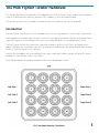
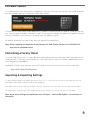
Midi Fighter Twister
User
Guide
Ver 1.01
DJTECHTOOLS.COM
Introduction
This user guide is split in two parts, first covering the Midi Fighter Twister hardware, then the second covering the Midi Fighter Utility and all relevant device settings.
If you are simply looking to learn how to set up and use an existing mapping in either Traktor or Ableton,
please refer to the quick start guides, these are both available here.
djtechtools.com/midifighterhelp
Nomenclature
The Musical Instrument Device Interface (MIDI) protocol at its most basic level describes 16 channels,
each consisiting of 128 Notes, and 128 Control Change (CC) messages.
This user guide and the Midi Fighter Utility refers to these 16 channels as channels 0 through 15, the notes
as notes 0 through 127, and the control change messages as CC’s 0 through 127.
2
The Midi Fighter Twister Hardware
This section describes the hardware & MIDI operation of the Midi Fighter Twister in detail and should be
used as a reference when creating your own MIDI mapping in your software of choice.
This section assumes that the reader is already familiar with the basics of the MIDI protocol.
Introduction
The Midi Fighter Twister consists of 16 encoders each with an integrated push switch, and 6 side buttons.
Each encoder has a display consisting of 11 white LEDs to indicate the current control value or position, a
large RGB segment which indicates the switch state, and a red/blue LED to indicate detent state.
The Midi Fighter Twister firmware makes it possible to access up four virtual ‘Banks’ or ‘groups’ of encoders. To access the virtual banks ensure that some of the side buttons are configured for bank change
actions in the Midi Fighter Utility Software.
Each of the 16 encoders will send a different message in each bank, allowing access of up to 64 unique
encoder & switch controls across the 4 banks.
For a full description of the bank operation refer to the virtual bank section.
3
Encoders
Each encoder sends a CC, note, or relative encoder messgae depending on its configuration, with the
current value indicated on its 11 LED display. There are a variety of user configurable display types, these
are covered in the Midi Fighter Utility section of this user guide.
It is possible to sync the display value of the CC or note to the parameter it is controlling in your software
of choice. Simply map the MIDI OUT for that parameter to the same MIDI number on channel 0.
Using the Midi Fighter Utility it is possible to remap the MIDI channel and number for each encoder.
Please note that the MIDI OUT display controls are not able to be remapped.
Encoders Push Switches
Each encoder also has an integrated push switch, this will send a CC (default), a Note message, or perform some special action depending on its configuration.
Please refer to the Midi Fighter Utility section of the manual for a full desription of the various available
switch actions.
The large RGB segment at the 6 o’clock position of each encoder display is used to indicate the state of
the switch control, using the Midi Fighter Utility it is possible to set the color for both the inactive (not
pressed) and the active (pressed) switch state.
It is also possible to overide the color of the RGB segment by sending a MIDI message (Note or CC) of
the same MIDI number, on channel 1. Sending a message of value 0 will force it to its inactive color state,
while sending a message of value 127 will force it to is active color state. Any value between 0 and 127 will
set it to a color as shown in the scale below.
1
126
4
Setting RGB Segment Animation State
By sending MIDI message of a particular value it is also possible to set a variety of animation states for
each ring, these animations modify the current color state of the ring illumination.
The available animation states are,
Strobe | Value 1 - 8
Allows the user to gate (flash) the current color at one of 7 different rates. If a MIDI clock signal is present the timing is derived from that, otherwise the timing is based on a half second interval which is the equivalent of 120 BPM. This is useful for creating warnings, for example in Traktor you could map the Track End Warning output to flash an LED when the track is nearing its end.
Pulse | Value 9 - 17
Similar to the Gate animation this allows the user to pulse the current color at one of 8 different rates. If a MIDI clock is present the timing is derrived from that otherwise the timing is based on a half second interval which is the equivalent of 120 BPM. This animation is useful for creating sub
tle alerts, for example in Traktor you could map the Loop On output to control the pulse rate to reflect that the loop is active, and what length it is set to.
Rainbow | Value 127
Forces the LED to display a rainbow animation.
To set the animation state of a given encoder send a CC or Note On message of the same number, but
on channel 2.
ie To set the animation state of the first encoder to Gate 1/4 send a Ch2 CC 0 of value 5.
It is important to note that the MIDI color setting and MIDI animation setting can be used in conjunction.
ie. To set the first encoder to yellow flashing at a rate of 1/2 first send the color information with a Ch1 CC0 of value 64, then the animation setting with a Ch2 CC0 of value 4.
If the encoder switch MIDI channel or number settings are changed from default the color and animation
controls do NOT change, ie if you change Encoder 1 in Bank 1 from channel 1 number 0 to channel 5 number 8 it will send MIDI on channel 5 number 8, but its color and animation controls will stay at channel 1
number 0 and channel 2 number 0 respectivley.
5
Side Buttons
Using the utility the 6 side buttons can be configured to send notes, CCs, or perform certain internal
functions like changing the bank selection.
If a side button is set for MIDI function the pitch of the note or CC number will be unique in each virtual
bank. This can be disabled by unchecking the “Bank Side Button” check box in the Utility.
Side button MIDI messages are sent on Channel 3.
Please refer to the utility section of this user manual for a complete description of the various side button
functions.
In Appendix 1 you will find a complete list of MIDI data for each side button in each bank.
6
Virtual Bank Operation
The Midi Fighter Twister makes it possible to access up to four virtual banks. In each bank the encoders,
encoder switches and side buttons* will send different MIDI Notes or CC’s.
To switch between virtual bank the side buttons must be configured to allow bank switching. By default
the middle left side button decrements the bank selection, and the middle right side button increments
the bank selection. Please refer to the side button section of this manual for further information.
*Side buttons can be set to not change with bank by disabling the “Bank Side Buttons” option in the Utility.
Advanced Bank Control
It is also possible to use MIDI to read and set the currently selected bank.
When the virtual bank selection changes the Midi Fighter Twister sends a Note On to indicate a new bank
has been selected. It will also send a Note Off to indicate the previously selected bank is no longer active.
By default the bank selection notes are sent on MIDI Channel 3.
ie When changing from Bank 1 to Bank 2 the Midi Fighter Twister will send a Ch3 C-1 Note Off followed by a Ch3 C#-1 Note On.
By sending Note On messages to the Midi Fighter Twister it is also possible to force it to automatically
change to a specific bank.
ie To force a change to Bank 2 send a Ch3 C-1 Note on
Bank Change Notes
Bank 1
Bank 2
Bank 3
Bank 4
|
|
|
|
Ch3 C-1
Ch3 C#-1
Ch3 D-1
Ch3 D#-1
7
The Midi Fighter Utility Software
This section covers the Midi Fighter Utility software. This is an application for PC & Mac that can be used
to control, configure, and update your Midi Fighter Twister.
Getting Started
The Midi Fighter Utility software can be downloaded using the following links.
Download For Mac
Download For PC
Once this has been installed you will find a shortcut on your desktop if using PC, or you can find the utility in your Applications folder if using Mac.
To get started launch the application and connect your Midi Fighter Twister to a spare USB port.
Note: If the Midi Fighter Utility does not detect the Midi Fighter Twister please make sure all other MIDI software has been shut down, then restart the utility and reconnect the device.
8
Firmware Update
It is important to ensure your device is loaded with the latest firmware. You can tell if you need to update
your firmware by looking at the device information section.
If the device firmware needs to be updated the “Update Firmware” button will display in orange, and the
text “new firmware available” will display in red. If the firmware is already up to date the ‘Update Firmware’
button will display in grey and the text “up to date” will appear in green.
To update the device firmware simply click the update firmware button.
Note: When updating the firmware do not connect the Midi Fighter Twister via a USB HUB, this may lead to a bricked device.
Performing a Factory Reset
Using the Midi Fighter Utility it is possible to restore all device settings and color information back to the
factory defaults. If you are having trouble with your Midi Fighter Twister this can be a good place to start
when diagnosing the problem.
To perform a factory reset connect your Midi Fighter Twister to the Utility and in the menu bar click,
Tools>Midi Fighter>Factory Reset
Importing & Exporting Settings
It is possible to import and export device settings, this is useful for saving and sharing device settings
and color information used for a particular mappings.
To export your settings click File>Export Settings and enter the name you wish to save the file under.
To import your settings click File>Import Settings and select the settings file you wish to load.
Note: Once these settings are loaded you must still press “Send to Midi Fighter” to save them to
the device.
9
Configuring your Midi Fighter Twister
There are two different types of settings for the Midi Fighter Twister, global settings and encoder settings.
Global settings are not related to any particular encoder, while the encoder settings are unique for each
of the 16 encoders in each of the 4 virtual banks.
The global settings are found under the “Global Settings” tab in the left hand pane of the utility, while the
encoder settings for the currently selected encoder are displayed in the “Encoder Settings” tab.
Any edits you make must be saved to the device by clicking the large blue ‘Send To Midi Fighter’ button.
Editing Encoder Settings
The Encoder Settings can be found under the “Encoder Settings” tab in the left hand pane of the utility
and are unique to each encoder in each bank.
To select an encoder for editing first select its bank by clicking one of the bank buttons, and then select
the encoder by clicking on it, the circular blue cursor indicates the currently selected encoder.
Editing Encoder Color Settings
Each encoder has two different color settings types, On Color (switch is pressed) and Off Color (switch is
released). The color pallete at the top right of the window is used to set the color of the currently selected encoder, and color setting type. To change which color setting type is being edited use the buttons at
the bottom right of the window.
Editing Multiple Encoders
It is possible to set certain settings for multiple encoders at the same time, this is called ‘Multiple Edit”
mode. To access this mode click the ‘Multiple’ button in the lower right hand side of the utilty. You can
now select multiple encoders (in the same bank only) and modify the available settings in the “Multiple
Edit” tab on the left hand pane of the utility.
To save any edits made in Multiple Edit mode you must press the ‘Send to Midi Fighter’ button, to cancel
with out applying any changes just click ‘Cancel’ and it will discard the changes and return to single edit
mode.
10
The Encoder Settings
The following is a description of all available encoder settings.
Enable Detent
If enabled the encoder will behave like a potentiometer with a center detent. Commonly used for controling EQ or filter settings. In this mode it’s LED display will start from the middle rather than the left hand side, and when its value is 50% (a MIDI Value of 64) the LED will change color to indicate this.
Detent Color
This can be used to change the color of the detent indicator, which is a red blue LED. A value of 0 will select red, while a value of 127 will select blue, and any value between will be a mix of the two.
Sensitivity
There are two sensitivity settings, ‘Responsive’ for which 270 degrees of rotation changes the CC by the full MIDI range of 127, or ‘High Resolution’ which gives the highest resolution control.
Indicator Type
The indicator type setting changes how the encoder value is displayed on the LED ring. There are three options; Dot which is a single LED, Bar which is a bar graph style display, and Blended Bar where the leading LED changes in brightness as the position changes, this gives the most de
tailed indication of position.
11
Enable Super Knob
If enabled the encoder will send a secondary CC over the range specified by the Super Knob Start & End points in the Global Options.
Encoder Switch Action Type
Each encoder switch can be set to perform one of a range of actions.
CC Hold
The switch will send a CC of value 127 when pressed and a CC of value 0 when released.
CC Toggle
The switch will alternate between sending a CC of value 127 and a CC of value 0 each time it is pressed.
Note Hold
The switch will send a Note On of velocity 127 when pressed and a Note Off of velocity 0 when released.
Note Toggle
The switch will alternate between sending a Note On and a Note Off each time it is pressed.
Reset Encoder Value
When pressed the switch will reset the encoder value to 0, or 64 if Detent is enabled. In this mode the switch also sends a MIDI message as if it where configured for CC hold.
Encoder Fine Adjust
When pressed the encoder sensitivity is reduced allowing fine adjustment.
Shift Encoder Hold
While the switch is pressed the encoder sends a secondary value, allowing one encoder to control two knobs independantly.
Shift Encoder Toggle
When pressed the switch toggles between primary and secodary (shift) encoder values.
12
Encoder MIDI Type
Each encoder can be configured to send either of the following MIDI messages
Note
The encoder sends Note On messages where the velocity corresponds to the Encoder Value.
CC
The encoder send Control Change messages with a value corresponding to the Encoder Value.
Enc 3FH/41H
The encoder sends relative Control Change messages, a value of 65 is sent for each clock
wise step, and a value of 63 is sent for each anti-clockwise step.
Encoder & Encoder Switch MIDI Number & Channel
You can set the MIDI number (pitch if configured as a Note) and Channel for each encoder and encoder switch in each bank. Be aware that if you change from the defaults it could conflict with other MIDI sent by the Twister. Check the appendix for a full listing of all the default MIDI messag
es for the Twister. Please note that this only effects MIDI OUT from the Twister, MIDI IN cannot be modified.
13
Global Settings
The global settings can be found under the “Global Settings” tab in the left hand pane of the utiltiy. This
section of this user guide contains a complete description of the available global settings.
Super Knob Start & End Point
If an encoder is enabled as a ‘Super Knob’ it will send a secondary CC over a range defined by the super knob start and end point values.
The start and end point values are global setting and will apply to all encoders which have ‘Super Knob’ enabled.
Bank Side Buttons
If the ‘Bank Side Buttons’ option is enabled then the side buttons will send unique MIDI for each bank. If it is disabled then the side buttons will send the same MIDI regardless of which bank is selected.
Side Button Functions
Each of the 6 side buttons can be set to perform one of a variety of actions.
CC Hold
The button will send a CC of value 127 when pressed and a CC of value 0 when released.
CC Toggle
The button will alternate between sending a CC of value 127 and a CC of value 0 each time it is pressed.
Note Hold
The button will send a Note On of velocity 127 when pressed and a Note Off of velocity 0 when released.
Note Toggle
The button will alternate between sending a Note On and a Note Off each time it is pressed.
Shift Page A or B
When held the button the MIDI sent by the encoder switches is modified, effectivley giving you instant access to an extra bank of buttons. In the shift state the encoder ring LEDs are used to indicate the switch state, you can control these LEDs by mapping a MIDI output to the same note and channel sent by the switch. There are two of these ‘Shift Pages’, A & B.
14
Next Bank
When pressed the bank selection will increase by one. If the device is in bank four it will have no action.
Previous Bank
When pressed the bank selection will decrease by one. If the device is in bank 1 it will have no action.
Cycle Bank
When pressed the bank selection will increase by one. If the device is in bank 4 it will select bank 1.
Bank 1, 2, 3, or 4
When pressed the bank selection will change to the specified bank.
15
Appendix 1
Bank 1 MIDI
Control
Ch
CC #
Note
LH Side Switch 1*
LH Side Switch 2*
LH Side Switch 3*
RH Side Switch 1*
RH Side Switch 2*
Rh SIde Switch 3*
3
3
3
3
3
3
8
9
10
11
12
13
G#-1
A-1
A#-1
B-1
C0
C#0
* Side Switch MIDI only changes with bank when the “Bank Side Button” option is enabled.
Control
Enc Ch
Enc CC #
Switch Ch
Switch CC
Switch Note*
Encoder 1
Encoder 2
Encoder 3
Encoder 4
Encoder 5
Encoder 6
Encoder 7
Encoder 8
Encoder 9
Encoder 10
Encoder 11
Encoder 12
Encoder 13
Encoder 14
Encoder 15
Encoder 16
0
0
0
0
0
0
0
0
0
0
0
0
0
0
0
0
0
1
2
3
4
5
6
7
8
9
10
11
12
13
14
15
1
1
1
1
1
1
1
1
1
1
1
1
1
1
1
1
0
1
2
3
4
5
6
7
8
9
10
11
12
13
14
15
C-1
C#-1
D-1
D#-1
E-1
F-1
F#-1
G-1
G#-1
A-1
A#-1
B-1
C0
C#0
D0
D#0
* Encoder Switch MIDI type defaults to CC
16
Appendix 1 contd...
Bank 2 MIDI
Control
Ch
CC #
Note
LH Side Switch 1*
LH Side Switch 2*
LH Side Switch 3*
RH Side Switch 1*
RH Side Switch 2*
Rh SIde Switch 3*
3
3
3
3
3
3
14
15
16
17
18
19
D0
D#0
E0
F0
F#0
G0
* Side Switch MIDI only changes with bank when the “Bank Side Button” option is enabled.
Control
Enc Ch
Enc CC #
Switch Ch
Switch CC
Switch Note*
Encoder 1
Encoder 2
Encoder 3
Encoder 4
Encoder 5
Encoder 6
Encoder 7
Encoder 8
Encoder 9
Encoder 10
Encoder 11
Encoder 12
Encoder 13
Encoder 14
Encoder 15
Encoder 16
0
0
0
0
0
0
0
0
0
0
0
0
0
0
0
0
16
17
18
19
20
21
22
23
24
25
26
27
28
29
30
31
1
1
1
1
1
1
1
1
1
1
1
1
1
1
1
1
16
17
18
19
20
21
22
23
24
25
26
27
28
29
30
31
E0
F0
F#0
G0
G#0
A0
A#0
B0
C1
C#1
D1
D#1
E1
F1
F#1
G1
* Encoder Switch MIDI type defaults to CC
17
Appendix 1 contd...
Bank 3 MIDI
Control
Ch
CC #
Note
LH Side Switch 1*
LH Side Switch 2*
LH Side Switch 3*
RH Side Switch 1*
RH Side Switch 2*
Rh SIde Switch 3*
3
3
3
3
3
3
20
21
22
23
24
25
G#0
A0
A#0
B0
C1
C#1
* Side Switch MIDI only changes with bank when the “Bank Side Button” option is enabled.
Control
Enc Ch
Enc CC #
Switch Ch
Switch CC
Switch Note*
Encoder 1
Encoder 2
Encoder 3
Encoder 4
Encoder 5
Encoder 6
Encoder 7
Encoder 8
Encoder 9
Encoder 10
Encoder 11
Encoder 12
Encoder 13
Encoder 14
Encoder 15
Encoder 16
0
0
0
0
0
0
0
0
0
0
0
0
0
0
0
0
32
33
34
35
36
37
38
39
40
41
42
43
44
45
46
47
1
1
1
1
1
1
1
1
1
1
1
1
1
1
1
1
32
33
34
35
36
38
39
40
41
42
43
44
45
46
47
48
G#1
A1
A#1
B1
C2
C#2
D2
D#2
E2
F2
F#2
G2
G#2
A2
A#2
B2
* Encoder Switch MIDI type defaults to CC
18
Appendix 1 contd...
Bank 4 MIDI
Control
Ch
CC #
Note
LH Side Switch 1*
LH Side Switch 2*
LH Side Switch 3*
RH Side Switch 1*
RH Side Switch 2*
Rh SIde Switch 3*
3
3
3
3
3
3
26
27
28
29
30
31
D1
D#1
E1
F1
F#1
G1
* Side Switch MIDI only changes with bank when the “Bank Side Button” option is enabled
Control
Enc Ch
Enc CC #
Switch Ch
Switch CC
Switch Note*
Encoder 1
Encoder 2
Encoder 3
Encoder 4
Encoder 5
Encoder 6
Encoder 7
Encoder 8
Encoder 9
Encoder 10
Encoder 11
Encoder 12
Encoder 13
Encoder 14
Encoder 15
Encoder 16
0
0
0
0
0
0
0
0
0
0
0
0
0
0
0
0
48
49
50
51
52
53
54
55
56
57
58
59
60
61
62
63
1
1
1
1
1
1
1
1
1
1
1
1
1
1
1
1
48
49
50
51
52
53
54
55
56
57
58
59
60
61
62
63
C3
C#3
D3
D#3
E3
F3
F#3
G3
G#3
A3
A#3
B3
C4
C#4
D4
D#4
* Encoder Switch MIDI type defaults to CC
19
Appendix 2
Animation Settings
Velocity / CC Value
Animation
Setting
0
None
-
1
Gate
Toggles on every 4 Beats
2
Gate
Toggles on every 2 Beats
3
Gate
Toggles on every Beat
4
Gate
Toggles every 1/2 Beat
5
Gate
Toggles every 1/4 Beat
6
Gate
Toggles every 1/8 Beat
7
Gate
Toggles every 1/16 Beat
8
Gate
Toggles every 1/32 Beat
9
Pulse
Brightness cycles over 16 Beats
10
Pulse
Brightness cycles over 8 Beats
11
Pulse
Brightness cycles over 4 Beats
12
Pulse
Brightness cycles over 2 Beats
13
Pulse
Brightness cycles every Beats
14
Pulse
Brightness cycles every 1/2 Beat
15
Pulse
Brightness cycles every 1/4 Beat
16
Pulse
Brightness cycles every 1/8 Beat
127
Rainbow Cycle
Fixed at 4 beat cycle rate
20