1
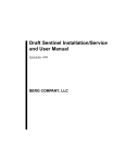
The Pinball Interface Gadget (PIG) – User Manual
The Pinball Interface Gadget
[PIG]
User Manual
Read this entire product manual before proceeding!
** Disclaimer: The Pinball Interface Gadget (PIG) is an advanced skill level
product made to be used by people who have knowledge of how electricity
flows and how electronics work. To use this device safely you must possess
basic electrical knowledge and technical skills. Soldering, wire cutting, wire
stripping, wire crimping, putting screws into wood, and identifying sources of
electrical signal are among the skills required to use the PIG safely. If you do
not have the requisite electronics knowledge and skills, find a qualified
technician to install the PIG! **
** Refer to your manufacturer’s warranty. Any modification to the original
game may void your warranty. Even if it’s really cool.
1|Page
The Pinball Interface Gadget (PIG) – User Manual
2|Page
The Pinball Interface Gadget (PIG) – User Manual
Table of Contents
The PIG Layout .............................................................................................................................................. 4
Power-In ........................................................................................................................................................ 5
Power-Out ..................................................................................................................................................... 6
Power Output Connector .......................................................................................................................... 6
Molex Power IN and Power OUT Kit ......................................................................................................... 7
Control .......................................................................................................................................................... 8
Power Outputs .......................................................................................................................................... 8
Signal Inputs .............................................................................................................................................. 8
Inverting Switch ........................................................................................................................................ 8
Signal Inputs ................................................................................................................................................ 10
Example Signal Connection Photos ......................................................................................................... 11
OUT1 – DIMMED: Detailed Explanation ..................................................................................................... 12
Inverting Switches: Detailed Explanation ................................................................................................... 12
Advanced – Building the POWER INPUT connector.................................................................................... 13
Advanced – Splicing into power connections ............................................................................................. 14
Advanced – POWER INPUT Connector for WPC Games ............................................................................. 15
Advanced – POWER INPUT Connector for Williams System 7 through System 11 games and Data East
games .......................................................................................................................................................... 16
Advanced – External Power Source ............................................................................................................ 17
Advanced – Connecting a Microcontroller ................................................................................................. 18
3|Page
The Pinball Interface Gadget (PIG) – User Manual
The PIG Layout
The PIG, put simply, distributes and controls power going to your electronic
pinball mods.
1: Signal Inputs 1-4
2: 5v Dimmer – Only affects Output 1 “DIMMED”
3: 12v Dimmer – Only affects Output 1 “DIMMED”
4: Power Input
5: Pass Through Output (Straight through, no PIG effects)
6: Output 1 – Controlled by Input 1
7: Output 1 DIMMED – Controlled by Input 1 and is dimmable with [2] and [3]
8: Output 2 – Controlled by Input 2
9: Output 3 – Controlled by Input 3
10: Output 4 – Controlled by Input 4
11: AUX – This is where you can connect your Microcontroller.
See: Advanced – Connecting a Microcontroller
12: Logic Inverting Switches
13: 5v circuit fuse – 2A Fast Blow
14: 12v circuit fuse – 2A Fast Blow
4|Page
The Pinball Interface Gadget (PIG) – User Manual
Power-In
First, we have to start with getting power to the PIG. There are a few ways to accomplish this.
There is a single power input on the PIG. To be specific, it is a .093 molex 3 circuit “plug”. There are
three male pins in the plug. Pin 1 is Ground, Pin 2 is +5v, and Pin 3 is +12v. (Pin 1 is on the “pointed
end” of the plug)
If you have a modern Stern pinball machine, getting power is
easy. Just inside the coin door, on the right side of the cabinet,
you will find a matching power receptacle. You can connect
this directly to your PIG and you will have the power that you
need.
If you are using the PIG in a machine that does not have this
plug, then you will need a power adapter cable for your
machine. See the “Advanced: Building the POWER INPUT
connector” section of this manual.
** Important ** While working with your PIG, it is VERY IMPORTANT not to rest your PIG on anything
made of metal while it is powered on. The coin box inside most games has a metal lid and unfortunately
is a convenient place to rest your PIG. Do not put the PIG on the coin box or anything else made of metal
while it is powered on! **
5|Page
The Pinball Interface Gadget (PIG) – User Manual
Power-Out
Now that you have your PIG powered, you can begin using it to power your mods. There are 6 power
receptacles. (Molex manufactures the connectors. They call the “female” plastic connector a “PLUG”
and the male plastic connector a “RECEPTACLE”.)
The pins on the outputs correspond to the pins on the input. Pin 1 is ground, Pin 2 is +5v, and Pin 3 is
+12V. (Pin 1 is on the “pointed” end).
Many pinball mods for Stern games, like DK Custom Pinball’s FLYNN’S sign, have been produced with
this connector. You may find that your mod will connect directly to the PIG without modification.
Otherwise, you will have to “build” a connector for your mod.
For each mod you want to power, you will need:
Power Output Connector
QTY 1 - Molex Part #03-09-2032
This is the plastic connector. (Note: This part number doesn’t have the little plastic wings. Having the
wings doesn’t hurt anything; they’re just annoying if you don’t actually need them.)
QTY 3 – Molex Part #39-00-0302
This is the metal pin.
You can order these parts from just about any electronics distributor.
OR … See next page
6|Page
The Pinball Interface Gadget (PIG) – User Manual
Molex Power IN and Power OUT Kit
Molex also sells a kit (Part#1396PRT) that you can find at many vendors like Mouser Electronics, Fry’s,
DigiKey, etc.
This kit contains all the parts you need to make 3 mod connectors and a power connector. You will
have parts left over because the kit contains enough parts to make both male and female connectors.
Crimping
If you are only making a few connectors, you can get away with using needle nose pliers and a soldering
iron to make a good connection to your wires with the metal pin.
If you plan on making a lot of connectors, I recommend getting the proper crimping tool. A decent tool
can be found at http://greatplainselectronics.com. The part number is 1026-CT. You can also buy the
official Molex tool (Part#63819-1200), which is very nice but also 10x the cost of the tool from Great
Plains Electronics.
7|Page
The Pinball Interface Gadget (PIG) – User Manual
Control
Power Outputs
The PIG has 6 Power outputs labeled, OUT 1, OUT 1 DIMMED, OUT 2, OUT 3, OUT4, and PASS THROUGH.
The PASS THROUGH output is always on as long as there is power to the POWER IN. If you have mods
that need constant power as long as the game is on, this is the output that you should use.
Signal Inputs
The PIG has 4 signal inputs that correspond to the power outputs. They are labeled IN1,
IN2, IN3, IN4.
IN1 controls OUT 1, and OUT1 DIMMED
IN2 controls OUT 2
IN3 controls OUT 3
IN4 controls OUT 4
Supplied with your PIG are 4 interface wires with alligator clips on one end and a 2 pin .100 connector
on the other end.
Inverting Switch
On each output channel, there is also a switch. This switch inverts the logic.
Input is normally off, then this switch will make the output normally on. If the
input is normally on, then this switch will make the output normally off.
8|Page
The Pinball Interface Gadget (PIG) – User Manual
This is where it all comes together.
-
With the power to your game switched OFF, connect the POWER IN to your power supply.
Connect your mod to OUT 1 on the PIG.
Make sure the switch on OUT 1 is switched toward the outside edge of the board.
Be certain that the PIG is either permanently mounted to the cabinet using the provided screws
and spacers or it is sitting securely in a place where it cannot make contact with any metal parts
such as the coin box.
Turn on your game.
Nothing Happens. This is because there is no signal going to IN 1. As long as there is no signal to IN1,
the power will remain OFF.
If you now move the OUT 1 switch toward the inside of the board, your mod will turn on and it will stay
on. This is because the switch inverts the logic. As long as there is NO signal to IN1, the mod will stay
ON.
-
Slide the switch back to the off position (toward the outside edge of the board)
Turn your game off, and connect the white .100 connector to IN1 on the PIG. The connector has a
locking ramp to help prevent you from connecting it incorrectly.
9|Page
The Pinball Interface Gadget (PIG) – User Manual
Signal Inputs
It’s now time to choose a signal source. Before you proceed, the disclaimer bears repeating:
** Disclaimer: The Pinball Interface Gadget (PIG) is an advanced level product made to be used by
people who have knowledge of how electricity flows and how electronics work. To use this device safely
you must possess basic electrical knowledge and technical skills. Soldering, wire cutting, wire stripping,
and wire crimping among the skills required to use the PIG safely. If you do not have the requisite
electronics knowledge and skills, find a qualified technician to install the PIG! **
You need to know what a short circuit is and why it is bad. The PIG was built with some isolation and
protection in mind, but connecting the signal wire improperly can still cause damage. It is possible for
you to bridge the positive and negative electrical leads going to a lamp, switch, or other electrical source
with a single alligator clip. If this happens then your game could act unpredictably and/or serious
damage could occur to your machine.
Be very careful connecting your signal wires to signal sources!!
Signal sources that have been tested and approved with the PIG are:
Insert Lights
General Illumination
Switches on the Switch Matrix
Flashers
DO NOT CONNECT THE SIGNAL WIRES TO:
Power sources rated over 20v.
Coils
Motors
The PIG has been made using an isolating chip that is rated for AC or DC. You do not need to worry
which clip goes on the power or ground of the source.
Lights and Switches that are on a matrix have a Diode. The diode is not connected the same way on
every game, so you may need to experiment with which side of the diode you clip the lead. If the signal
does not work as expected, move the lead connected to the diode to the other side of the “stripe”.
See the next page for example photos
10 | P a g e
The Pinball Interface Gadget (PIG) – User Manual
Example Signal Connection Photos
Signal Clips connected to GI
Signal Clips connected to an Insert Lamp
Signal Clips connected to a Switch
Signal Clips connected to a flasher
11 | P a g e
The Pinball Interface Gadget (PIG) – User Manual
Once you have chosen a signal source and have connected your IN1 signal lead to it, use zip straps to
securely fasten the wire to points on the wiring harness in a path back to the PIG. This will mitigate the
risk of the clips coming off when raising and lowering the playfield. The signal wires were intentionally
made long to accommodate properly fastening the wire to wiring harness and routing the cable safely
back to the PIG.
…. And that’s it. Your mod is now incorporated with your game. You have the freedom to try a few
different signal sources before settling on one. Once you decide, I would recommend removing the
alligator clips and soldering the wires to the signal source in order to make sure you have a reliable
electrical connection that will last for years.
You can now add other mods to the other channels.
OUT1 – DIMMED: Detailed Explanation
OUT1 uses the signal from IN1 to turn on and off. There is another option. If you connect your mod to
OUT1 DIMMED.
OUT 1 DIMMED can also be controlled by the two potentiometers (volume
controls) on the PIG. One control corresponds to the 5v pin on OUT1
DIMMED, the other control corresponds to the 12v pin on OUT1 DIMMED.
This is not dynamic. It’s a set and forget type option. You may find that the
light being turned on and off is too bright, and you can use this output to
dim the light. This is the only output on which you can make this
adjustment.
Inverting Switches: Detailed Explanation
The four out channels each have a logic switch. By default, when the
signal (light, GI, flasher) is off, then the output is off. However, there is an
exception –Switches. When a switch (a switch that is NO – Normally Open)
is closed, it’s essentially a short. Measuring voltage across a closed switch
will show 0v.
When the switch is open, there is now a difference in voltage between one side and the other. So with
the switch open, you will then show a voltage. Somewhere around 5v.
A normally closed switch will do the opposite. It can get a little confusing. The simple answer is that the
switch is there to make your mod do what you want it to do. If you want the light ON when another
light is on, or a switch it pressed, or a flasher is flashing, then you move the switch to the position that
works for that mod.
12 | P a g e
The Pinball Interface Gadget (PIG) – User Manual
Advanced – Building the POWER INPUT connector
** Disclaimer: The Pinball Interface Gadget (PIG) is an advanced level product made to be used by
people who have knowledge of how electricity flows and how electronics work. To use this device safely
you must possess basic electrical knowledge and technical skills. Soldering, wire cutting, wire stripping,
and wire crimping among the skills required to use the PIG safely. If you do not have the requisite
electronics knowledge and skills, find a qualified technician to install the PIG! **
** All work should be done with the power off and the game unplugged!
I recommend that you start by purchasing a Molex 3 Circuit .093 series kit as shown on Page 5 of this
manual. Or you can order individual parts listed below.
To make the connector you require:
QTY 1 Molex Part Number – 03-09-1033
This is the plastic connector. (Note: This part number doesn’t have the little plastic wings. Having the
wings doesn’t hurt anything; they’re just annoying if you don’t actually need them.)
QTY 3 – Molex Part #02-09-1119
This is the metal pin.
You can order these parts from just about any electronics distributor.
Use 18 Gague stranded wire. Three different colors, Black for Ground, Red for +5, and Yellow for +12 is
my preference, but the color does not affect the function of the connector. The following pages will
explain some methods and places to get power from your game.
13 | P a g e
The Pinball Interface Gadget (PIG) – User Manual
Advanced – Splicing into power connections
** Disclaimer: The Pinball Interface Gadget (PIG) is an advanced level product made to be used by
people who have knowledge of how electricity flows and how electronics work. To use this device safely
you must possess basic electrical knowledge and technical skills. Soldering, wire cutting, wire stripping,
and wire crimping among the skills required to use the PIG safely. If you do not have the requisite
electronics knowledge and skills, find a qualified technician to install the PIG! **
** All work should be done with the power off and the game unplugged!
The easiest way to tap into a wire is to use a 3M Scotchlok connector. They can be found at most auto
parts stores because they’re often used for installing car stereos and trailer lights.
Here is an excerpt from the 3M™ Scotchloc™ Insulation Displacement Electrical Tap Connector 560B
Data Sheet. In the past, I have used a pair of pliers (the kind with jaws that hinge to grab bigger things)
to push down the metal tab (U-contact).
14 | P a g e
The Pinball Interface Gadget (PIG) – User Manual
Advanced – POWER INPUT Connector for WPC Games
** Disclaimer: The Pinball Interface Gadget (PIG) is an advanced level product made to be used by
people who have knowledge of how electricity flows and how electronics work. To use this device safely
you must possess basic electrical knowledge and technical skills. Soldering, wire cutting, wire stripping,
and wire crimping among the skills required to use the PIG safely. If you do not have the requisite
electronics knowledge and skills, find a qualified technician to install the PIG! **
** This is meant to be used as a guide, not a definitive resource for power connections on Williams
pinball machines.
** All work should be done with the power off and the game unplugged!
Families of pinball games and boards tend to stay the same year after year. Williams / Bally games, post
System 11, have a fairly consistant layout, and power can be taken from the same place on many of
these games.
Before you tap into these power sources, you should verify that the pins and voltages match the
schematics for the game with a multi-meter. ** If you don’t know how to use a multi-meter, you should
hire a technician to do this for you!
This example comes from a Williams / Bally Twilight Zone. I have found that the locations are the same
on Road Show, Johnny Mnemonic, No Fear, and other games. If you have a 90’s era WPC game, this is a
good place to start looking.
On the Power Driver Assembly board, (located in the lower right hand side of the back box) locate the
connector labeled J114. It is a 7 pin connector with pin 6 removed.
Pin 1 – Gray/Green wire, +12v DC
Pin 2 – Not Used
Pin 3 – Gray, +5v DC
Pin 4 – Not Used
Pin 5 – Not Used
Pin 6 - Removed
Pin 7 – Black – Ground
Connect wire on Pin 7 to PIN 1 on the PIG Power Input
Connect wire on Pin 3 to PIN 2 on the PIG Power Input
Connect wire on Pin 1 to PIN 3 on the PIG Power Input
15 | P a g e
The Pinball Interface Gadget (PIG) – User Manual
Advanced – POWER INPUT Connector for Williams System 7 through
System 11 games and Data East games
** Disclaimer: The Pinball Interface Gadget (PIG) is an advanced level product made to be used by
people who have knowledge of how electricity flows and how electronics work. To use this device safely
you must possess basic electrical knowledge and technical skills. Soldering, wire cutting, wire stripping,
and wire crimping among the skills required to use the PIG safely. If you do not have the requisite
electronics knowledge and skills, find a qualified technician to install the PIG! **
** This is meant to be used as a guide, not a definitive resource for power connections on Williams or
Data East pinball machines.
** All work should be done with the power off and the game unplugged!
Going over schematics and testing in various machines, I have found that Williams System 7 through
System 11 games (the same may be true of older Williams Solid State games, I have not explored back
that far) have a consistent power source.
In most Williams games, the Power Supply board is in the upper right hand side of the back box. Data
East games, the power supply is on the upper left hand side.
There is a 15 pin logic power connector on these boards. Using F-14 Tomcat as an example, it is labeled
3J6. On Data East Tales from the Crypt, it is labeled CN6.
Pin 1 – Not Used
Pin 2 - -12v (This is negative 12v, don’t use this one)
Pin 3 - Unused
Pin 4 - Unused
Pin 5 - Unused
Pin 6 - +12v DC
Pin 7 - +5v DC
Pin 8 - +5v DC
Pin 9 - +5v DC
Pin 10 - +5v DC
Pin 11 – GND
Pin 12 – GND
Pin 13 – GND
Pin 14 – GND
Pin 15 - Unused
Connect wire on Pin 11 to Pin 1 on the PIG Power Input
Connect wire on Pin 10 to Pin 2 on the PIG Power Input
Connect wire on Pin 6 to Pin 3 on the PIG Power Input
16 | P a g e
The Pinball Interface Gadget (PIG) – User Manual
Advanced – External Power Source
** Disclaimer: The Pinball Interface Gadget (PIG) is an advanced level product made to be used by
people who have knowledge of how electricity flows and how electronics work. To use this device safely
you must possess basic electrical knowledge and technical skills. Soldering, wire cutting, wire stripping,
and wire crimping among the skills required to use the PIG safely. If you do not have the requisite
electronics knowledge and skills, find a qualified technician to install the PIG! **
A PC power supply can be connected to your service outlet or an external power strip. The down side of
this solution is that the power will remain on with the game off. There are modifications that you can
make to the service outlet to make it switch with the game which are documented on the internet. I
recommend you find those instructions online as they are beyond the scope of this document.
You can buy a regular PC power supply, or this product is available through Amazon.com.
Coolerguys 110v AC to 12v / 5v DC 4 Pin Molex 2A Power Adapter. This connector is essentially an
external IDE CD ROM/Hard Drive/Fan power supply.
An adapter can be made by using the power connector on Page 11 of this manual and these parts
Pin 1 +12v / Pin 2 GND / Pin 3 GND / Pin 4 +5v
Kobiconn Power Connector 163-4012-EX
QTY 4 of Molex pin Part #39-00-0302
With this power adapter and a PIG, with the exception of the signal lines (which are isolated using an
optocoupler) you would have the greatest isolation of your mods from your game. It is the least
intrusive option next to using the plug available on Stern machines.
17 | P a g e
The Pinball Interface Gadget (PIG) – User Manual
Advanced – Connecting a Microcontroller
All of the possible applications for the microcontroller interface are beyond the scope of this document.
I will put it plainly. When working on this board, I imagined ways that it could be connected to a
microcontroller to make even more advanced modifications.
You may want to connect your microcontroller to a signal in the game, and then do power switching on
an external mod. Rather than having to replicate the input and output portions of my circuit each time
you want to make a mod involving a microcontroller, you can insert the inputs and outputs into the PIG
circuitry.
Pictured here, you can see 2 rows of 4 pins with
jumpers on them. The bottom row of pins will provide
a clean 0 or 5v signal based on what the “IN#”
connectors are connected to.
The top row of pins will turn on or off the power to
OUT1 – OUT4 based on a 0v (off) or 5V (on) logic signal.
You can choose to remove one, or all of the jumpers to
insert your Arduino or other microcontroller into the
circuit. (Using the proper connector .100 connector).
Connect the bottom row of pins to INPUT pins on the
microcontroller and connect the top row of pins to the OUTPUT pins on the microcontroller. Then the
coding is up to you and your imagination.
Proper Connector
FCI Part#71600-108LF
2 rows of 4 – Available at Mouser
Possible Uses
I can imagine where you might use the input signal on a switch to have the microcontroller turn on a
light for 10 seconds.
You could have a switch trigger the microcontroller to start a light slowly pulsing and then speeding up
over 10 seconds until the light turns off.
Another suggestion would be to use the microcontroller to create AND/OR logic. If an insert light is on,
AND a switch is pressed, then flash a series of lights on the outputs.
The microcontroller could decouple the IN and OUT. One in could control 3 outs, or vice versa.
18 | P a g e