1
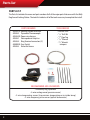
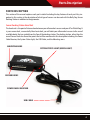
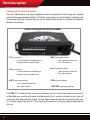
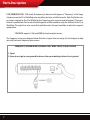
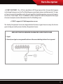
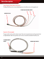
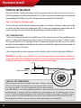
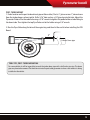
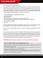
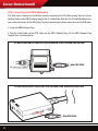
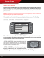
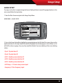
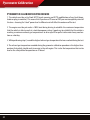
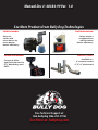
USER MANUAL: SENSOR DOCKING STATION W/ PYRO
Part #
Bully Dog Sensor Docking Station with
Pyrometer
40384
Works with the following products
40420 Triple Dog GT Diesel
40425 Triple Dog GT Diesel (50 state legal version)
40410 Triple Dog GT Gas
40400 Watch Dog (white)
40402 Watch Dog (black)
(Units must be at software version 1.1.4.0 or later)
Table of Contents
TABLE OF CONTENTS
INTRODUCTION....................................................................................PG. 2
PARTS LIST...........................................................................................PG. 3
PARTS DESCRIPTION..........................................................................PG. 4-9
Sensor Docking Station Head Unit................................................................. pgs. 4
Sensor Docking Station Docks (ports)......................................................... pgs. 5-8
Power Wire Harness..................................................................................... pgs. 9
Pyrometer (Thermocouple).......................................................................... pgs. 9
PRE VS. POST TURBO PYROMETER INSTALLATION.................................PG. 10
PHYSICAL INSTALLATION.............................................................. PGS. 11-15
Step 1: Installing the Pyrometer............................................................ pgs. 11-12
Pre-turbo installation..................................................................................................................................... 11
Post-turbo installation.................................................................................................................................... 12
Step 2: Installing the Sensor Docking Station...........................................pg. 13-14
Step 3: Connecting to the OBDII Adapter Plug................................................pg.15
SYSTEM STATUS CHECK........................................................................PG. 16
CALIBRATING SENSORS IN THE GT SOFTWARE.................................. PG. 17-19
Pyrometer Setup..........................................................................................pg. 17
Analog Sensor Calibration.............................................................................pg.18
Frequency Sensor Calibration........................................................................pg.19
GAUGE SETUP (DISPLAY SENSOR VALUES ON SCREEN)...........................PG. 20
PYROMETER CALIBRATION PROCEDURE...............................................PG. 21
NOTES................................................................................................PG. 22
1
Introduction
INTRODUCTION
The Bully Dog Sensor Docking Station accommodates the installation of aftermarket sensors on a vehicle
by receiving those sensor inputs and then sending the input signals to the Bully Dog GT diesel, GT gas,
and WatchDog. Go to our sensor information page within this manual to review the different types of
sensors and input types that the Sensor Docking Station can accept. The Sensor Docking Station does not
work with monitoring or tuning products other than Bully dog products.
Software version 1.1.4.0 or later required?
All GTs and WatchDogs must be updated to version 1.1.4.0 or later to work properly with the Bully Dog
Sensor Docking Station.
Installation Difficulty
This installation can be difficult depending on the level of knowledge of the installer. This installation
does require the exhaust manifold or the post turbo exhaust down pipe to be drilled and tapped. It is
recommended that professional assistance is utilized if the installer does not have experience with drilling and tapping.
2
Parts List
PARTS LIST
The Parts list includes the name and part numbers of all of the major parts that come with the Bully
Dog Sensor Docking Station. The tools list indicates all of the tools necessary to complete the install.
PARTS INCLUDED
40383-10 Docking Station Head Unit
40383-2 Pyrometer Thermocouple
40383-20 Power wire harness
40383-1 Velcro pad and 6 zip ties
40383-4 Ring Terminal connectors (2)
40400-20 Fuse Tap kit
40383-3 Dielectric Grease
TOOLS NEEDED
• Electric Drill
• 5/16” Drill Bit
• 1/8” Pipe Tap
• 9/16” Wrench
• 5/8” Wrench
• crimpers
RECOMMENDED ADD-ON SENSORS
• Extra Bully Dog Pyrometer
• 3-wire analog sensor (pressure sensor)
• 2-wire temperature sensor (transmission temperature or air intake temp)
• 2-wire frequency pulse sensor (optical tachometer)
3
Parts Description
PARTS DESCRIPTION
This section of the manual explores each part in detail including the key features of each part. Very important in this section is the description of what type of sensors can be used with the Bully Dog Sensor
Docking Station in addition to the pyrometer.
Sensor Docking Station Head Unit
The head unit is the point of intersection between your aftermarket sensors and your GT or WatchDog. It
is your sensor dock, so essentially like a boat dock, you will dock your aftermarket sensors to the row of
available docks that are available on the face of the docking station. The docking station, other than the
row of Sensor Docks has four other points that will be mentioned in this description including: the Power
Cable Receiver, the System Status Light, the USB Cable, and the Mounting arms.
MOUNTING ARMS
SYSTEM STATUS LIGHT (GREEN LIGHT)
SENSOR DOCKS
POWER CABLE RECEIVER
USB CABLE
4
Parts Description
Docking Stations (ports) Descriptions
There are 12 docks (ports) that accept stripped bare wire that can be from 22 to 12 gauge wire. Exposed
wire length for proper docking should be 3/8”. Below is a description of each of the docks, including what
they are and what type of sensors they can receive. Before the descriptions is a diagram that properly
identifies the locations.
DOCK LOCATION IDENTIFICATION DIAGRAM
• P1: Pyro location #1
• AN 2: Analog input location 2
Y+: Positive yellow wire on Bully Dog Pyro
+ AN 2: signal wire in from sensor
R-: Negative red wire on Bully dog Pyro
- AN 2: optional ground
• P2: Pyro location #2
• AN 3: Analog input location 3
Y+: Positive yellow wire on Bully Dog Pyro
+ AN 3: signal wire in from sensor
R-: Negative red wire on Bully Dog Pyro
- AN 3: optional ground
• AN 1: Analog input location 1
+ AN 1: signal wire in from sensor
- AN 1: optional ground
• F/IN: Frequency Signal IN
• +5V/ OUT: 5 volt supply/ Signal Out
P1 (PYRO 1): P1 stands for Pyro 1 because it will appear as Pyro 1 in the Gauge Setup menu on the GT
or WatchDog once everything has been installed correctly. Pyro 1 contains two docks or ports that will
accept only Bully Dog pyrometer signals. The two docks include the dock for the positive yellow wire
(Y+) and the negative red wire (R-). Bully Dog Type K Pyrometers are the only approved pyrometer for
this unit.
5
Parts Description
P2 (PYRO 2): P2 stands for Pyro 2 because it will appear as Pyro 2 in the Gauge Setup menu on the GT
or WatchDog once everything has been installed correctly. Pyro 2 contains two docks or ports that will
accept only Bully Dog pyrometer signals. The two docks include the dock for the positive yellow wire
(Y+) and the negative red wire (R-). Bully Dog Type K Pyrometers are the only approved pyrometer for
this unit.
AN 1 - AN 3 (ANALOG 1-3): AN 1-3 will appear in the AUX 1-3 gauge location in the Gauge Setup menu
on the GT or WatchDog once everything has been installed correctly. Note that further sensor setup is
required on the GT or WatchDog for Analog sensors to read out properly. Sensor manufactures specifications for sensor input and output will be required for proper setup. The typical three wire sensor that
could be used in this application would include a Manifold Pressure Sensor, or an Oil Pressure Sensor.
AN + DOCK: supports a 0-5 Volt signal wire from analog sensors.
AN - DOCK: acts as an optional ground, but should not be used in substitute
for a chassis ground, it is recommended that sensors needing a ground share the
same ground as the PWR Cable for the Sensor Docking Station head unit.
The analog sensor wiring diagram illustrates a typical three wire setup. Use this diagram to help you
install your own analog sensors into any of the three analog sensor docks.
ANALOG SENSOR WIRING DIAGRAM FOR 3 WIRE 0-5 VOLT ANALOG SENSOR
1. Power in (5-12 VDC depending on sensor), key on power only.
2. Signal out (0-5 VDC only)
3. Ground, must go to the same ground location as the sensor docking station chassis ground.
6
Parts Description
F/IN (FREQUENCY IN): F/IN stands for Frequency in because it will appear as “Frequency,” in the Gauge
Setup menu on the GT or WatchDog once everything has been installed correctly. Note that further sensor setup is required on the GT or WatchDog for a frequency pulse sensor to read out properly. The manufacturer’s specifications for the rate of incoming pulses will be needed to setup the software in the GT or
WatchDog. The typical two wire sensor that could be used in this port would be an optical or magnetic
speed sensor.
F IN DOCK: supports 5 Volt and 5000 Hertz pulse output sensors
The Frequency sensor wire diagram below illustrates a typical two wire setup. Use this diagram to help
you install your own frequency pulse sensors.
FREQUENCY SENSOR WIRE DIAGRAM FOR 2 WIRE PULSE SIGNAL SENSOR
1. Signal
2. Ground, must go to same ground location as the sensor docking station chassis ground.
7
Parts Description
+ 5V OUT (AUX TEMP): The +5V Out is identified as AUX Temp. because that is the way that it appears
in the Gauge Setup menu on the GT or WatchDog once everything has been installed correctly. The typical two wire sensor that could be used in this port would be a liquid temperature sensor or air temperature sensor (2 wire Delphi). There is no additional software setup that needs to take place for these types
of sensors to output accurate information to the GT or WatchDog screen.
+ 5V OUT: supports 0-5 Volt temperature sensors
The Auxiliary Temperature Sensor wire diagram below illustrates a typical two wire setup. Use this diagram to help you install your own Auxiliary Temperature Sensors.
AUXILIARY TEMP SENSOR WIRE DIAGRAM FOR 2 WIRE TEMP SENSOR
1. Signal
2. Ground, must go to same ground location as the sensor docking station chassis ground.
8
Parts Description
Sensor Docking Station Power wire harness
The Power Wire Harness has a sensor dock plug on one end and three wires on the opposite end.
POWER AND GROUND WIRES
HARNESS PLUG
Pyrometer (Thermocouple)
The pyro installs into the vehicle’s exhaust system. There are two important parts on the pyrometer that
are depicted below. Note that a pyrometer such as this one cannot be extended with ordinary wire.
THERMOCOUPLE
BUNG
9
SENSOR DOCK WIRES
Pyro: Pre Vs. Post
PYROMETER MOUNTING: PRE-TURBO VS. POST-TURBO
What are the determining factors in deciding whether to install the pyrometer probe in a preturbo location or a post-turbo location?
The location of the pyrometer probe along the stream of exhaust gas will make a considerable difference
in the temperatures that will display on the GT or WatchDog. An incorrect interpretation of the readings
can lead to vehicle damage, so it is very important to have a clear understanding of the differences between Pre-turbo and Post-turbo. Consider the following:
1. DIFFICULTY OF THE INSTALL: Before installing, inspect the exhaust manifold and the turbo down
pipe of the vehicle and determine which location will make for the easiest install. Many vehicles will have
an obviously easier position for installation. Despite the thermocouple location, the Pyrometer Calibration Procedure can always be used to determine a safe range of operation.
2. ENGINE CONFIGURATION: If the vehicle is a V8 and the intention is to install a pre-turbo pyrometer,
then really two pyrometers should be installed, one pyrometer in each exhaust manifold bank to detect
any difference between each bank of cylinders. If the vehicle engine is a straight six like the Dodge Cummins, then installing pre-turbo or post turbo can be done easily and mounting in both locations is also
very possible.
3. HORSEPOWER OUTPUT: If the vehicle is running significantly more horsepower than stock (100+
horsepower), it is strongly advised that both a pre-turbo pyro probe and post-turbo pyro probe be installed. Both pyrometers should be installed within the recommended distances from the turbo charger.
4. DETERMINING A SAFE OPERATING RANGE: The pyrometer calibration procedure allows the driver
to see the maximum temperatures achievable with a stock vehicle and from there helps determine a safe
range of temperatures to use while the vehicle has performance enhancing tunes installed. The pyrometer calibration procedure would also be used to determine where to set safety defueling points if using
the pyrometer on a GT diesel or PMT.
5. PREFERABLE MOUNTING LOCATION: Mounting the pyrometer probe pre-turbo is generally recommended because it provides more accurate EGT readings. Mounting the pyrometer probe preturbo actually provides closer to real time temperatures and more accurate temperatures because it
is closer to the actual combustion event taking place inside the engine. Pre-turbo temperatures will
display the intensity of the heat coming out of the engine and will indicate the temperature of the
exhaust gas that is entering the turbo charger. A post turbo pyrometer probe will only indicate the
temperature of gas exiting the turbo charger.
10
Pyrometer Install
PHYSICAL INSTALLATION
Physical installation should always begin with the pyrometer and any other sensors that are to be installed. The purpose of installing the pyrometer first is that it is limited on its cable length so installing the
Sensor Docking Station first may result in the pyrometer not reaching the Sensor Dock.
Step 1: Installing the Pyrometer probe
In this section you will drill and tap the pyrometer probe in the exhaust, either pre-turbo or post-turbo
as a means to collect exhaust gas temperatures (EGT). Exhaust gas temperatures indicate how hot the
engine is getting and can be used to set safety defueling parameters for diesel vehicles.
PRE-TURBO MOUNTING:
1. Drill a 5/16” hole into the exhaust manifold where all the exhaust runners of the manifold come together, 3” in front of the turbo charger exhaust inlet. Try to be with in plus or minus 1” of the 3” target.
Then tap the hole with a 1/8” pipe tap and mount the pyrometer probe in the hole. Use a 9/16” wrench
to tighten the probe holder or tube fitting to the exhaust manifold. Then tighten the top pyro probe nut
to the holder using a 5/8” wrench.
2. Run the pyro cable up to the engine bay; let the end of the cable sit while installing the PCH Board.
WARNING: If any debris such as drill bits and metal shavings drop inside the exhaust manifold, it is
strongly advised that the manifold be removed from the vehicle so that the debris can be removed before
starting the vehicle again. Such debris can cause damage to a turbo charger.
3”
Exhaust Manifold
TOOL TIPS, PRE-TURBO MOUNT
When drilling into the exhaust manifold, metal spews, shavings, and broken
drill bits can fall inside. Try following these steps to prevent debris from falling into the manifold: 1. Use a high quality twist bit and a slow speed drill,
about 500-800 rpm. 2. Start with a small pilot bit about 1/8”, then use the full 5/16” bit after the smaller one has
punched through. 3. Grease your drill bit in addition to the normal lubricant, this will catch flying spews as they
are cut. 4. Just prior to punching through into the inside of the manifold, start the engine and build up exhaust
pressure on the inside of the manifold (blows spews outside the manifold instead of letting them fall inside). 5.
Also magnetize the drill bit so any excess shavings will be magnetically drawn to the drill bit.
11
Pyrometer Install
POST-TURBO MOUNT
1. Find a location on the post turbo exhaust pipe or “down tube,” that is 3”, plus or minus 1”, downstream
from the turbo charger exhaust outlet. Drill a 5/16” hole and run a 1/8” pipe tap into the hole. Mount the
Pyrometer Probe in the threaded hole using a 9/16” wrench to tighten the probe holder or tube fitting to
the down tube. Then tighten the top Pyro Probe nut to the holder using a 5/8” wrench.
2. Run the Pyro Cable along the brim of the engine bay, and then let the end sit when installing the PCH
Board.
3”
Exhaust Down pipe
TOOL TIPS, POST-TURBO MOUNTING
For some vehicles it will be impossible to reach the turbo down pipe with a drill and a pipe tap. The down
pipe may have to be removed. The ideal time to install a post turbo pyrometer is when a new exhaust is being
installed on the vehicle.
12
Sensor Station Install
Step 2: Installing the Sensor docking station
In this step the Sensor Docking Station needs to be mounted in a secure location within the reach of the
end of the pyrometer cable. The power wire harness plug will be plugged into the Power Cable receiver
and the power and ground wires will need to be connected. Next, connect the pyro cable along with any
other sensors that have been installed to the sensor dock. The final step will include running the USB
cable into the cab of the vehicle and then securing any and all loose wires.
1. Gather the following parts in preparation for installation:
• Sensor Docking Station
• Power wire harness
• Ring Terminal Connectors for ground wires(18-22 AWG with 3/8” ring)
• Fuse Tap and Spade connector for key on power (spade should have a 18-22 AWG end)
• Velcro with adhesive (optional)
• Zip Ties (6)
2. The Sensor Docking Station needs to be mounted in a location that is secure (away from extreme heat
and moving parts), and in a location that the end of the Pyrometer Cable(s) can easily reach.
3.Use the zip ties or Velcro, or both to securely attach the PCH Board to a safe location within the
engine bay.
4.Connect the power wire harness to the Sensor Docking Station by simply inserting the plug end of the
power wire harness into the PWR receiver on the Sensor Docking Station face. Next, connect the three
wires on the end of the harness according to the wiring diagram on the next page below. Please read the
warning below before proceeding with the installation of the power wire harness. Use the ring terminal
connectors for the ground wires and the fuse tap kit for the key on power wire.
IMPORTANT Connect the ground wires of the power wire harness before connecting the power wire.
TOOL TIPS, HOW TO IDENTIFY A KEY ON POWER SOURCE (FUSE)
This requires two people. Your key on power source will most likely exist inside the vehicle fuse box, however some
vehicles do have accessory wires that are made especially for this purpose. This tool tip however will explore the
traditional key on fuse power source.
1. Have one person touch the end of a simple voltage detector to the small exposed part of a fuse. If the fuse
provides power with the key off, it is not a key on power source.
2. Repeat that step but look for a fuse that does not immediately provide power. Once one is found then have the
second person turn the key to the on/run position. If the fuse provides power only while the key is on then this is a
key on power source and will work for this installation.
13
Sensor Station Install
POWER WIRE HARNESS INSTALLATION DIAGRAM
5. Connecting the Pyro Cable or any other sensor: first remove the sheathing from the end of the red and
yellow leads. Then apply a dielectric grease to the exposed wire on the end of each lead. The dielectric
grease will protect the bare wire. To secure the leads in the docks, simply press the leads straight into
the docks below. An internal mechanism will clamp down on the leads to hold them in place. See the
photos below.
6. Run the end of the USB Cable through the fire wall. It will need to be connected to the OBDII Adapter
Plug. Use zip ties to secure all remaining cable left inside the engine bay.
14
Sensor Station Install
STEP 3: Connecting to the OBDII Adapter plug
This final step in the physical installation involves connecting the USB cable coming from the Sensor
Docking Station to the OBD ll Adapter plug for the GT or WatchDog. Note that the GT and Watchdog have a
new and an old version of the OBD ll plug. The illustrations below indicate where to insert the USB cable.
1. Locate the OBDII Adapter Plug.
2. Plug the Cradle Cable and the PCH Cable into the OBD II Adapter Plug. See the OBD II Adapter Plug
Diagram for a visual description.
GT/WATCHDOG OBD II ADAPTER PLUG DIAGRAM (FIRST GENERATION DESIGN)
Mini USB PLUG
Main Harness Support
From GT/WatchdogCradle
GT/WATCHDOG OBD II ADAPTER PLUG DIAGRAM (2ND GENERATION DESIGN)
←
15
Mini USB PLUG
System Status Check
SYSTEM STATUS CHECK (THE GREEN LIGHT)
The system operating check allows you to quickly check to see that the system is hooked up properly and
that the Sensor Docking Station is communicating with the GT or WatchDog.
1. Locate the green LED on the face of the Sensor Docking Station.
2. Turn the key to the run position and observe the status of the green LED.
3. The green LED should behave in one of three different ways:
STATUS 1: Solid Green Light indicates that the system is working properly and that the unit is communicating properly with the GT or WatchDog.
STATUS 2: Blinking Green light indicates that the Sensor Docking Station is powered up correctly and
that it is trying to establish communication with the GT or WatchDog. If it never establishes communication with the GT or WatchDog, check the connection to the OBD ll port and also check to make sure that
the GT or WatchDog is installed correctly and working properly. If problem persists then call technical
support.
STATUS 3: No light indicates that the sensor docking station is not getting proper power. Be certain that
all of the wires on the power wire harness are hooked up properly and that the power wire harness plug
is plugged in correctly.
16
Sensor Setup
SENSOR SETUP AND CALIBRATION OF THE SENSORS
The Following Sensor types require some kind of setup and or Calibration in the GT software:
• Pyro 1 and 2 (Pyrometers)
• Analog Gauge Locations
• Frequency
Reminder: the sensor docking station will not work with the GT or WatchDog unless they are updated to
software version 1.1.4.0 or later.
The following three sections will describe how to perform the initial setup for the above sensor types so
they will display properly on your GT or WatchDog. After setup has been performed properly, the sensor
must be selected from the Gauge Setup menu to display them on the screen.
Pyrometer Setup
The default pyrometer setting for any GT or WatchDog is to display an OEM installed pyrometer. This section will show you how to change the GT or WatchDog so that they will display the Bullydog pyrometer.
1. Navigate to the select pyro source screen in GT or WatchDog:
MAIN MENU > VEHICLE SETUP > SELECT PYRO SOURCE
Go Back
PYRO SOURCE
Choose to display Factory Pyro data or data from
your Bully Dog Pyro Kit.
Factory Pyro
Bully Dog Pyro Kit
2. The diagram shows the screen shot from the product. Select the pyro source that says Bully Dog pyro.
Once selected, simply exit that screen and the pyro source has now been changed. Now if pyro 1 or pyro
2 is selected from the gauge setup menu, the value that is displayed will be the value that is collected
from the Bully Dog pyrometer.
17
Sensor Setup
Analog Sensor Calibration
Every analog sensor should have information regarding the manufacturer’s voltage output and display
value range. If not, this information must be gathered from the manufacturer of the sensor. The GT and
WatchDog will not be able to interpret the sensor signals unless the manufacturer’s specs are correctly
entered. Calibration for each of analog sensor input on the Sensor Docking Station is the same, so the
calibration procedure will not vary, regardless of the sensor location (1,2, or 3).
Manufacturer’s sensor specs: The manufacturer should have a voltage output range (inputs on GT or
WatchDog) and display range values. The voltage outputrange (this manual refers to this as “high and
low inputs”) will vary between 0-5 volts. The display range values are those values that make up the total
range for the information displayed on your GT or WatchDog screen.
1. Once the inputs and outputs have been gathered, navigate to the Set Sensor Settings screen in GT or
WatchDog and then select the desired analog sensor to be setup:
MAIN MENU > USER OPTIONS > SET SENSOR SETTINGS >ANALOG 1,2, OR 3
2. Go through each of the input screens and enter the OEM
spec inputs and outputs in each of the input and output
screens. Read the input and output entry notes below for help
with understanding how to properly enter those values.
Go Back
ANALOG 1
to sensor menu
Set Input Low
Set Input High
Set Output Low
• ENTERING INPUTS: The input low and the input high values
will range from 0-5 Volts. The OEM may label this as voltage
output rather than inputs as is described in this manual. Enter
in the exact OEM specification for the sensor voltage range.
Enter the low range value in the low input field and the high
range value in the high input field.
Set Output Hight
Cancel
ANALOG 1
Set Input Low
Sensor output at lowest input
Use the Up/Down arrows to change.
5.0
• ENTERING OUTPUTS: The Output low and high values, or
display values, can range between many different values. The
GT or WatchDog contains an allowable range of 0 - 1000 in 10
unit increments. If smaller increments are required simply act
as if the final zero has been dropped and use the 0-1000 range
as a 0-100 scale. Enter the low range value in the low output
field and the high range value in the high output field.
(range:0-1000 units)
Save
Cancel
ANALOG 1
Set Output High
Sensor output at highest input
Use the Up/Down arrows to change.
1000
(range:0-1000 units)
Save
18
Sensor Setup
Frequency Sensor Calibration
A frequency sensor will send out pulses that are then received by the Sensor Docking Station and get sent
to the GT or WatchDog in a 1:1 ratio. Available in the GT and WatchDog is a multiplier and a divisor menu
to adjust that 1:1 ratio into a more desired and familiar rate of output like pulses per minute rather than
pulses per second.
EXAMPLE: A typical optical sensor would output pulses per second. If pulses per minute was the desired
output then the pulse input could be multiplied by 60.
1. To modify the signal: navigate to the frequency multiplier and divisor screen in GT or WatchDog:
MAIN MENU > USER OPTIONS > SET SENSOR SETTINGS >FREQUENCY
Go Back
to sensor menu
FREQUENCY
Set Frequency Multiplier
Set Frequency Divisor
2. Once in the Frequency Sensor Menu there will be a Multiplier menu option and a divisor menu option
as seen in the diagram above. Read the notes below on the Multiplier screen and the Divisor Screen to aid
in understanding how those affect the pulse input signal.
• SETTING A MULTIPLIER: Once in the multiplier screen, the
signal multiplier can be adjusted from 1-60. The selected multiplier value will multiply the signal value by itself and display
the product on the GT or WatchDog Screen.
FREQUENCY
Cancel
Set Frequency Divisor
Use the Up/Down arrows to change
1
(range:1-60)
Save
• SETTING A DIVISOR: Once in the Divisor screen, the signal
divisor can be adjusted from 1-60. The selected divisor value
will divide the signal value by itself and display the quotient on the GT or WatchDog Screen.
19
Gauge Setup
GAUGE SETUP
To assign a value that is acquired using the Sensor Docking Station to one of the gauge locations in the
main screen follow the steps below.
1. From the Main Screen navigate to the Gauge Setup Menu.
MAIN MENU > GAUGE SETUP
Go Back
AUX Temp.
Setup Gauge 1
RPM
Setup Gauge 2
Throttle
Setup Gauge 3
GAGUE SETUP
GAUGE 1
Use the Up & Down Arrows to
Change the Gauge Function
AUX 3
AUX Temp.
Frequency
Load
Setup Gauge 4
2. Once in the Gauge Setup Menu highlight any gauge location on the left side of the screen, then use the
up/down buttons on the right side of the device to highlight the desired gauge or value. Below is a list
of all of the values or gauges, they way they would be labeled, if you were looking at the sensor docking
station:
• Pyro 1: Pyro location #1
• Pyro 2: Pyro location #2
• AUX 1: Auxiliary sensor location #1
• AUX 2: Auxiliary sensor location #2
• AUX 3: Auxiliary sensor location #3
• AUX Temp: + 5V out or temp sensor input
• Frequency: F IN or Frequency input
20
Pyrometer Calibration
PYROMETER CALIBRATION PROCEDURE
1. The vehicle must be set to Stock HP/TQ levels-meaning no HP/TQ modifications of any kind (downloader or plug-in modules). This means that if you have a GT tuner or PMT you must completely uninstall
the tune - choosing the “stock” power level is different and will affect the outcome of the test.
2. The engine must be put under a 100% load during driving to establish the maximum temperature
that the vehicle is able to reach at a stock horsepower rating. A good way to establish that the vehicle is
reaching a maximum exhaust gas temperature is to drive up a hill or pull a trailer under heavy acceleration on a hot day.
3. While performing step 2, record the highest exhaust gas temperature that was reached during the test.
4. The exhaust gas temperature recorded during the pyrometer calibration procedure is the highest temperature that vehicle should reach to remain in the safe region. This is also the temperature that can be
used as the safety defuel temperature on GT diesel.
21
Notes
22
Manual Doc #: 40384-99 Ver. 1.0
See More Products from Bully Dog Technologies
Cold Air Intakes
Fuel Reformulator
More air,
colder and
more dense air,
more power,
better efficiency.
Helps create a
complete burn
which creates
better efficiency.
Custom Pod Mounts
Exhaust Systems
Custom A-pillar
and Dash mounts for
GTs, Watchdogs and
PMTs.
Available in :
4” ceramic coated
4”, 5”, 6” aluminized
Free Technical Support at:
866-bullydog (866-285-5936)
See More at: bullydog.com


![The Pinball Interface Gadget [PIG] User Manual](http://vs1.manualzilla.com/store/data/005778998_1-4ef7b51c0feccb7069db304928e0e19c-150x150.png)