1
No. CP-SP-1153E
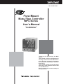
Panel Mount
Mass Flow Controller
MPC Series
User's Manual
"Installation"
Thank you for purchasing the MPC
Series.
This manual contains information for
ensuring correct use of the MPC Series.
It also provides necessary information
for installation, maintenance, and troubleshooting.
This manual should be read by those
who design and maintain devices that
use the MPC Series.
Be sure to keep this manual nearby for
handy reference.
RESTRICTIONS ON USE
This product has been designed, developed and manufactured for general-purpose
application in machinery and equipment.
Accordingly, when used in applications outlined below, special care should be taken to
implement a fail-safe and/or redundant design concept as well as a periodic
maintenance program.
• Safety devices for plant worker protection
• Start/stop control devices for transportation and material handling machines
• Aeronautical/aerospace machines
• Control devices for nuclear reactors
Never use this product in applications where human safety may be put at risk.
REQUEST
Ensure that this User's Manual is handed over to the user before the
product is used.
Copying or duplicating this User's Manual in part or in whole is forbidden. The information and specifications in this User's Manual are subject to change without notice.
Considerable effort has been made to ensure that this User's Manual is
free from inaccuracies and omissions.
If you should find any inaccuracies or omissions, please contact
Yamatake Corporation.
In no event is Yamatake Corporation liable to anyone for any indirect,
special or consequential damages as a result of using this product.
©2004 Yamatake Corporation ALL RIGHTS RESERVED
The µF logo is a trademark of Yamatake Corporation.
Micro Flow Sensor and MPC are trademarks of Yamatake Corporation.
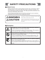
SAFETY PRECAUTIONS
■ About Icons
Safety precautions are for ensuring safe and correct use of this product, and for
preventing injury to the operator and other people or damage to property. You
must observe these safety precautions. The safety precautions described in this
manual are indicated by various icons.
As the following describes the icons and their meanings, be sure to read and
understand the descriptions before reading this manual:
WARNING
CAUTION
Warnings are indicated when mishandling this product might
result in death or serious injury to the user.
Cautions are indicated when mishandling this product might
result in minor injury to the user, or only physical damage to
this product.
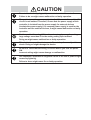
■ Examples
Triangles warn the user of a possible danger that may be caused by
wrongful operation or misuse of this product.
These icons graphically represent the actual danger. (The example on
the left warns the user of the danger of electric shock.)
White circles with a diagonal bar notify the user that specific actions are
prohibited to prevent possible danger.
These icons graphically represent the actual prohibited action. (The
example on the left notifies the user that disassembly is prohibited.)
Black filled-in circles instruct the user to carry out a specific obligatory
action to prevent possible danger.
These icons graphically represent the actual action to be carried out.
(The example on the left instructs the user to remove the plug from the
outlet.)
i
WARNING
Never allow gases that are within explosive limits to pass through this
controller.
Doing so might result in explosion accidents.
Do not use this controller for gases other than standard compatible gas
types (nitrogen/air, argon and carbon dioxide).
Do not use this controller for medical instruments.
CAUTION
Prevent foreign matter from entering the controller.
If the rust, water droplet, oil mist or dust in the piping flows into the
controller, measurement error might occur and result in damaging the
controller. If there is a possibility that are any foreign matter flows into
the controller, provide a filter or mist trap capable of eliminating more
than 0.1µ m foreign matter at the upstream, and periodically inspect
and replace the filter
Use this controller within the operating differential pressure range.
Also, do not apply pressure outside the pressure resistance range.
Doing so might damage this controller.
This controller is not provided with the capability of completely closing
the valve.
If the valve must be completely closed, provide a shutoff valve
separately. When an external valve is closed, must make the valve
standby by fully closing with either of the following methods:
• Make the flowrate to zero.
• Set the operation mode to the fully closed mode.
If this valve is maintained in control mode despite of closing the
external shutoff valve (zero flowrate), large excess flowrate will instantly
flow when the external shutoff valve is opened.
In the case of the MPC0020, if the external shutoff valve is closed for
more than 5 minutes under control mode or valve forced fully open the
AL7 1) operated and the valve driving current is
valve over-heat limit (A
forcibly limited. If this status exists for more than 30 minutes, the valve
is forced to full close condition.
When this controller is mounted on a panel, use piping which does not
give stress to the controller case during and after the piping work. If a
metal piping is directly connected to the pipe connection port of this
controller, the case might be deformed or damaged.
ii
CAUTION
Do not allow lead clippings, chips or water to enter this controller case.
Failure to do so might cause malfunction or faulty operation.
The part between the power supply circuit of this controller and the I/O
circuit is not isolated. Therefore, ensure that the power supply of this
controller is isolated from the power supply for external devices
(insulate the power supply). If a common power supply is used for the
controller and the external devices, it might cause malfunction or faulty
operation.
For the model with analog I/O function, do not apply a negative-voltage or
large voltage more than 5V to the analog setting input terminal.
Doing so might cause malfunction or faulty operation.
This device is a precision instrument. Do not drop it nor subject it to
shock. Doing so might damage the device.
Be sure to check that the wiring is correct before you turn the power
ON.
Incorrect wiring might cause damage or malfunction.
Use Yamatake Corporation's SurgeNon if there is the risk of power surges
caused by lightning.
Failure to do so might cause fire or faulty operation.
iii
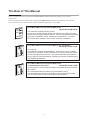
The Role of This Manual
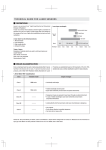
In all, 3 manuals have been prepared for the MPC Series. Read the manual according to your specific
requirements.
The following lists all the manuals that accompany the MPC Series and gives a brief outline of the manual:
If you do not have the required manual, contact Yamatake Corporation or your dealer.
C P - UM
U
-0123E
nual
ser's Ma
G
WARNIN
CAUTION
WARN
ING
N
CAU TIO
Panel Mount Mass Flow Controller MPC Series
Manual No.CP-UM-5317E
This manual is supplied with the product.
Personnel in charge of design and/or manufacture of a system using this
device must thoroughly read this manual. This manual describes the safety
precautions, installation, wiring, and primary specifications. For further
information about operation, refer to other manuals, "Installation".
Panel Mount Mass Flow Controller MPC Series "Installation"
Manual No.CP-SP-1153E
This manual.
This manual is optional (sold separately). Personnel in charge of design,
manufacture, operation, and/or maintenance of a system using this device
must thoroughly read this manual. This manual describes the installation,
wiring, major functions and settings, operating procedures, troubleshooting,
and detailed specifications.
Panel Mount Mass Flow Controller MPC Series
"Communications Functions"
Manual No.CP-SP-1154E
Those using the communications functions of the MPC series should read
this manual.
This manual describes an outline of communications, wiring,
communications procedures, a list of MPC series communications data,
how to remedy trouble, and communications specifications.
iv
Organization of This User's Manual
This manual is organized as follows:
Chapter 1. INTRODUCTION
This chapter briefly describes this device, its features and the model selection
guide.
Chapter 2. NAMES AND FUNCTIONS OF PARTS
This chapter describes the Names and functions of parts on this device.
Chapter 3. MOUNTING AND WIRING
This chapter describes installation, mounting, wiring and initial settings on this
device.
Chapter 4. BASIC OPERATION
This chapter describes the basic operations for using this device.
Chapter 5. APPLICATION OPERATION
This chapter describes how to set the functions and parameters on this device.
Chapter 6. TROUBLESHOOTING
This chapter describes how to investigate and remedy trouble that may occur
during operation of this device.
Chapter 7. SPECIFICATIONS
This chapter describes the specifications and external dimensions of this device.
v
Contents
SAFETY PRECAUTIONS
The Role of This Manual
Organization of This User's Manual
Conventions Used in This Manual
Chapter 1.
INTRODUCTION
■ Introduction • • • • • • • • • • • • • • • • • • • • • • • • • • • • • • • • • • • • • • • • • • • • • • • • • • • • • • • • • • • • 1-1
■ Functions • • • • • • • • • • • • • • • • • • • • • • • • • • • • • • • • • • • • • • • • • • • • • • • • • • • • • • • • • • • • • • 1-1
■ Model selection guide • • • • • • • • • • • • • • • • • • • • • • • • • • • • • • • • • • • • • • • • • • • • • • • • • • 1-4
Chapter 2.
NAMES AND FUNCTIONS OF PARTS
Chapter 3.
MOUNTING AND WIRING
■ Mounting • • • • • • • • • • • • • • • • • • • • • • • • • • • • • • • • • • • • • • • • • • • • • • • • • • • • • • • • • • • • • • • 3-2
■ Wiring • • • • • • • • • • • • • • • • • • • • • • • • • • • • • • • • • • • • • • • • • • • • • • • • • • • • • • • • • • • • • • • • • • 3-6
Chapter 4.
BASIC OPERATION
4-1 Switching Displays • • • • • • • • • • • • • • • • • • • • • • • • • • • • • • • • • • • • • • • • • • • • • • • • • • • • • • • • 4-1
4-2 Setting the Flowrate • • • • • • • • • • • • • • • • • • • • • • • • • • • • • • • • • • • • • • • • • • • • • • • • • • • • • • • 4-3
■ Procedure for changing flowrate in digital setting • • • • • • • • • • • • • • • • • • • • • 4-3
■ Procedure for changing flowrate in analog setting• • • • • • • • • • • • • • • • • • • • • 4-5
(a model with analog input / output function)
4-3 Selecting the Operating Mode • • • • • • • • • • • • • • • • • • • • • • • • • • • • • • • • • • • • • • • • • • • • • 4-6
Chapter 5.
APPLICATION OPERATION
5-1 Function Setup • • • • • • • • • • • • • • • • • • • • • • • • • • • • • • • • • • • • • • • • • • • • • • • • • • • • • • • • • • • • 5-2
■ Function setup item list • • • • • • • • • • • • • • • • • • • • • • • • • • • • • • • • • • • • • • • • • • • • • • • • 5-3
5-2 Parameter Setup • • • • • • • • • • • • • • • • • • • • • • • • • • • • • • • • • • • • • • • • • • • • • • • • • • • • • • • • • • • 5-6
Chapter 6.
TROUBLESHOOTING
■ Alarm code display • • • • • • • • • • • • • • • • • • • • • • • • • • • • • • • • • • • • • • • • • • • • • • • • • • • • 6-1
■ Other troubles • • • • • • • • • • • • • • • • • • • • • • • • • • • • • • • • • • • • • • • • • • • • • • • • • • • • • • • • • 6-2
Chapter 7.
SPECIFICATIONS
■ Specifications • • • • • • • • • • • • • • • • • • • • • • • • • • • • • • • • • • • • • • • • • • • • • • • • • • • • • • • • • • 7-1
■ Relationship between flowrate when valve is fully open and• • • • • • • • • • • 7-6
differential pressure (in air)
vi
Conventions Used in This Manual
The following conventions are used in this manual:
Handling Precautions
: Handling Precautions indicate items that the user should pay attention to
when handling the MPC Series.
Note
: Notes indicate useful information that the user might benefit by knowing.
: This indicates the item or page that the user is requested to refer to.
(1), (2), (3)
: The numbers with the parenthesis indicate steps in a sequence or
indicate corresponding parts in an explanation.
>>
: This indicates the contents shown on the personal computer or unit as a
result of operation or unit status after completion of operation.
0FF
: This indicates 7-segment indication on the setup display.
"OK" lamp
: This indicates an LED lamp on the setup display.
[ENT] key
: This indicates a key on the setup display.
vii
Chapter 1.
INTRODUCTION
■ Introduction
The MPC series high performance digital mass flow controller has been developed
for the general industrial market featuring high speed and wide range flowrate
control, the following features are offered:
• The MPC series integrates the advanced technologies of an ultra high speed
response flow velocity sensor, the µF (Micro Flow) sensor made using
Yamatake proprietary technology, an ultra compact proportional solenoid valve,
a new flow channel structure and advanced actuator control technology
achieves the realization of the mass flow controller, which can be mounted on
the panel of the equipments.
• This is a compact (48 X 48mm mask size) and light weight (approx. 300g) mass
flow controller.
• Easy operation and easy mounting can be realized in good harmony when
replacing from a float type flow meter. In addition, the automatic control of
mass flow rate and remote flow setting change can be performed.
• There is almost no influence of temperature and pressure fluctuations by
integrating a µF sensor.
• A wide variety of functions are provided as a standard function to respond to
the various needs of the users.
• In case of a float type flow meter, the pressure and temperature compensation is
inevitable. In addition, if the design conditions (gas specific gravity, secondary
back pressure, etc.) are different from the conditions for use, the reading value
is required to convert by a specific calculation formula. However, these
inconvenient operation is no more required with the mass flow control.
■ Functions
• Multi-setup function
Up to four preset flowrate settings can be instantaneously switched to by key
operation or external switching input.
• Gas type switching function
The gas type to be used can be selected from the standard compatible gases by
key operation.
• Gas type setting function
The user can set any gas type conversion factors to accommodate the gases
other than standard compatible gases or mixed gases.
• Valve forced open/close function (selecting the operation mode)
The valve can be forcibly fully opened or fully closed by key operation or
external switching input.
• Slow start function
Sudden changes in the control flowrate, when control is started or when the
flowrate setting value is changed, can be suppressed.
The control speed can be changed in eight stages within the range from about
1 to 6 seconds.
1-1
Chapter 1. INTRODUCTION
• Flowrate integration function
The fowrate can be integrated up to eight digits (99,999,999 count).
(The display is switched in four digits at a time.)
MPC9500:
0.01L in unit
MPC0002/0005: 0.1L in unit
MPC0020:
1L in unit
The count can be reset by key operation or external switching input.
Integration start/stop/reset can be remote-controlled by external switching
input.
After a reset by key operation, the integration calculation is started
automatically. However, if a reset (contact ON) is carried out by external
switching input, integration is resumed by the contact turning OFF.
• Valve drive output display
The valve drive output value can be displayed in the unit of 0.0 to 100.0%.
The increase or decrease of supply pressure and the choking of piping can be
detected.
• Alarm display/output/shut-off
The flowrate deviation alarm can be output by detecting the deviation between
setting flowrate and control flowrate. The alarm judgment delay time can also
be set. When a flowrate alarm occurs or an alarm occurs during controller selfdiagnostics, the event signal is output, the valve can be forcibly fully closed or
fully opened at your choise also.
• Event lamp lighting/output
Two of the following event types can be output:
• Alarm output (When the flowrate deviation alarm or self-diagnostics
occurs.)
• Flowrate upper/lower limit output (Output by comparison to the optional
upper/lower flowrate limit setting value.)
• Integration count up output (When the integration setting flowrate is
exceeded.)
• Integration pulse output (Pulse can be output for each integration display
unit.)
• OK output (When the control flowrate is within the range of "set point ±
allowable range".)
• The operating mode can be identified and output externally as an event.
The output ON delay time can also be set. However, the delay cannot be set to
integration pulse output. In addition, the output logic can be reversed (At
regular time: ON, at event occurrence: OFF). However, the output is always
OFF during power OFF.
• "OK" lamp lighting / output
The "OK" lamp can be made to light when the control flowrate is within the
“setting value ± allowable range”. This function is very handy for verifying at
a glance whether or not the new setting value is being followed properly when
a setting value is changed. "OK" lamp output can also be used as an interlock
signal for subsequent processes by assigning it to event output and loading it
to a sequence program.
1-2
Chapter 1. INTRODUCTION
• Automatic shut-off function
The valve can be shut off automatically under the following conditions:
However, the valve of this device does not have a capability of complete shutoff.
When the complete shut-off is required, provide a separate shut-off valve
externally.
(1) When the integration count value reaches the setting value.
(2) When one of the alarms, including flowrate alarms, occurs.
• Automatic reset of integration count at start of control function
Start of control and integration count reset can be carried out simultaneously
by a single action (key operation or external switching input). Combining this
function with the automatic shut-off function described above is handy for
shutting the valve off when a fixed number of integration values have been
counted repeatedly.
• Direct setup function
This function allows users to easily change the flowrate setup.
This function is useful when you frequently change setting values, for
example, when you adjust the preset flowrate during trial operation.
• Loader communication function
The connection of a dedicated loader cable (sold separately) to the loader jack
at the rear side of this device enables direct communication with a personal
computer in the form of one to one using the communication program made
by user. By using this loader communication, various settings in the function
setup and the flowrate setup can be configured from a personal computer, and
the control flowrate or alarm status can be read out with the personal
computer.
1-3
Chapter 1. INTRODUCTION
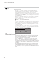
■ Model selection guide
Basic
Control
Dismodel No. flow range play
MPC
9500
0002
0005
0020
B
Mate- Connec- Gas No Option Option Option Option Code
rial
tion
type use
1
2
3
4
B
R
N
0
0
1
2
0
0
0
D
Y
0
Description
Panel mount mass flow controller
0.020 to 0.500 L/min(standard) *1
0.08 to 2.00 L/min(standard) *1
0.10 to 5.00 L/min(standard) *1
0.4 to 20.0 L/min(standard) *1
Model with integrated display
Brass
Rc1/8
Nitrogen / air *2
None
With analog input/output function
(without RS-485 communication function)
With RS-485 communication function
(without analog input/output function)
Without optional function
Without optional function
Without optional function
Inspection certificate provided
Complying with traceability certification
Product version
*1: L/min(standard) indicates the volume flowrate per minute (L/min) converted to 20°C, and 1
atmospheric pressure.
The reference temperature can also be changed to 0°C, 25°C and 35°C
*2: The nitrogen/air is set as a factory setting.
The MPC can be used for argon and carbon dioxide gases by setup change.
1-4
Chapter 2.
NAMES AND FUNCTIONS OF PARTS
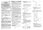
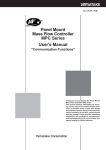
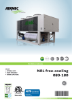
● Display
Upper display: Displays the instantaneous flowrate value
(7-segment display).
When the display is switched, it also displays the
integrated flowrate value (upper 4 digits),
parameter setup item, function setup item or alarm details.
MPC
PV
Lower display: Displays the set flowrate
(7-segment display).
When the display is switched, it also
displays the operation mode,
SP
integrated flowrate values (lower 4 digits),
value drive output, parameter setup values,
DISP
[DISP] key: Used when switching
function setup values.
the details of display.
Operation lamp
L
SP1
SP2
SP3
EV1
EV2
OK
L:
Indicates that the integrated flowrate is
displayed.
ENT
Flashes when an integration event occurs.
OK:
Lights when the control flowrate is within
the "setting value ± allowable range".
Flashes when the operating mode is valve
[<], [V], [ ]keys:
fully-open.
Used when incrementing/decrementing
SP1 to SP3: The lamp corresponding to the SP No.
the digit or moving to a desired digit.
which is used at multi-setup is lit.
EV1, EV2: Lights when the event output is ON.
[ENT] key:
Used when setting the SP value and storing
the value. It also can be used for the
integrated flowrate resetting and alarm
resetting.
Note
• The definition of the terms used in this manual is as follows:
SP (Set Point): Set flowrate value
PV (Process Variable): Instantaneous flowrate value (control flowrate)
Operation mode: 3 mode of "valve fully-closed / valve control / valve fully-open"
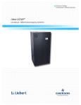
● Rear view
Loader jack:
Connects to a personal computer by
using a dedicated loader cable sold separately.
1 2
3 4
5 6 7 8 9
Connector:
Pipe connection outlet port:
This is the out flow side port.
Pipe connection inlet port:
This is the in flow side port.
2-1
Chapter 3.
MOUNTING AND WIRING
WARNING
Never allow gases that are within explosive limits to pass through this controller.
Doing so might result in explosion accidents.
Do not use this controller for gases other than standard compatible gas types
(nitrogen/air, argon and carbon dioxide).
CAUTION
Prevent foreign matter from entering the controller.
If the rust, water droplet, oil mist or dust in the piping flows into the controller,
measurement error might occur and result in damaging the controller. If there
is a possibility that are any foreign matter flows into the controller, provide a
filter or mist trap capable of eliminating more than 0.1µ m foreign matter at
the upstream, and periodically inspect and replace the filter.
Use this controller within the operating differential pressure range. Also, do
not apply pressure outside the pressure resistance range.
Doing so might damage this controller.
This controller is not provided with the capability of completely closing the
valve.
If the valve must be completely closed, provide a shutoff valve separately.
When an external valve is closed, must make the valve standby by fully
closing with either of the following methods:
• Make the flowrate to zero.
• Set the operation mode to the fully closed mode.
If this valve is maintained in control mode despite of closing the external
shutoff valve (zero flowrate), large excess flowrate will instantly flow when the
external shutoff valve is opened.
In the case of the MPC0020, the external shutoff valve is closed for more than
5 minutes under control mode or valve forced fully open the valve over-heat
limit (AL7 1) operated and the valve driving current is forcibly limited. If this
status exists for more than 30 minutes, the valve is forced to full close
condition.
When this controller is mounted on a panel, use piping which does not give
stress to the controller case during and after the piping work. If a metal piping
is directly connected to the pipe connection port of this controller, the case
might be deformed or damaged.
Do not allow lead clippings, chips or water to enter this controller case.
Failure to do so might cause malfunction or faulty operation.
The part between the power supply circuit of this controller and the I/O circuit
is not isolated. Therefore, ensure that the power supply of this controller is
isolated from the power supply for external devices (insulate the power
supply). If a common power supply is used for the controller and the external
devices, it might cause malfunction or faulty operation.
3-1
Chapter 3. MOUNTING AND WIRING
CAUTION
For the model with analog I/O function, do not apply a negative-voltage or large
voltage more than 5V to the analog setting input terminal.
Doing so might cause malfunction or faulty operation.
This device is a precision instrument. Do not drop it nor subject it to shock.
Doing so might damage the device.
Be sure to check that the wiring is correct before you turn the power ON.
Incorrect wiring might cause damage or malfunction..
Use Yamatake Corporation's SurgeNon if there is the risk of power surges
caused by lightning.
Failure to do so might cause fire or faulty operation.
■ Mounting
Avoid mounting this controller in the following locations:
• Locations subject to high and low temperature and humidity
• Locations subject to sudden changes in temperature and condensation
• Locations subject to be filled with corrosive gases and flammable gases
• Locations whose atmospheres contain large amounts of dirt and dust, salt,
conductive substances such as iron powder, water droplets, oil mist and organic
solvents
• Locations directly subject to mechanical vibration or shock
• Locations subject to direct sunlight and rain
• Locations subject to splashing of oil or chemicals
• Locations close to sources of electrical noise
• Locations where strong magnetic or electrical fields are generated
3-2
Chapter 3. MOUNTING AND WIRING
● Joint connection
• Connect the joint by holding the hexagonal section of the pipe connection port
of the body with a spanner (or wrench).
Handling Precautions
• Do not hold the case of the controller with your hand when screwing
the joint into the connection port. Doing so might deform the body.
• Screw the joint with an appropriate torque as recommended by the
joint manufacturer. Exceeding the torque limits will cause damage the
connection port.
• Apply appropriate amount of sealant. Do not coat the top most thread of the
screw. Remove any dirt or burrs from inside the joint.
Good example
Bad example
Sealant
Sealant
3-3
Chapter 3. MOUNTING AND WIRING
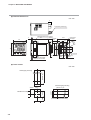
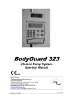
● External dimensions
unit: mm
9
Connector (accessory)
Mounting bracket (accessory)
61
12.7
Loader
jack
No.1
2
Connection
port OUT
3.5
EX
2-H
48
44.8
14
MPC
DISP
L
9.5
SP
OK
SP1
SP2
SP3
EV1
12
44.8
10
48
PV
EV2
ENT
2-Rc1/8
No.9
13.5
10
Connection
port IN
Applicable panel plate
thickness is 2 to 9mm
● Panel cutout
unit: mm
(48 X N -3)+0.5
0
Vertical gang-mounting
45 +0.5
0
20min.
3-4
45 +0.5
0
Individual mounting
(48 X N -3) +0.5
0
45 +0.5
0
45 +0.5
0
20min.
Horizontal gang-mounting
(N: Number of mounted units)
Chapter 3. MOUNTING AND WIRING
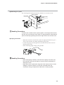
● Mounting on a panel
The mounting panel should be used with a thickness of 2 to 9mm of steel.
Mounting bracket
Panel cutout
Mounting bracket
screws
Hook
MPC
mm.
2 to 9
e thic
l plat
Pane
s is
knes
Panel
Handling Precautions
To fasten this controller onto the panel, tighten a mounting bracket screws,
and turn one more half turn when there is no play between the bracket and
panel. Excessively tightening the screws might deform the controller case.
● Piping connection
• When this controller is mounted on a panel, use piping which does not give a
stress to the controller case during and after the piping work.
• Connect the piping so that the gas flows in the direction from IN to OUT as
indicated on the body.
• After connecting piping, check for any gas leaks.
OUT
IN
Handling Precautions
• When metal piping is directly connected to the piping connection port,
this controller cannot be mounted on a panel. Doing so will deform or
damage the case.
• When leak check is performed using leak check liquid, ensure to avoid
spillage or contact of liquid on to the case, electrical wires and
connectors. Doing so mightcause malfunction or faulty operation.
3-5
Chapter 3. MOUNTING AND WIRING
■ Wiring
CAUTION
Be sure to check that the wiring is correct before you turn the power ON.
Incorrect wiring might cause damage or malfunction.
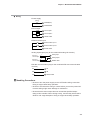
● Connector specifications
• Part No.: MCVW1.5 / 9-STF-3.5 (Phoenix Contact Mfg.)
• Wire type: Either of single core wire or stranded wire applicable.
• Compatible cable: 0.08 to 1.5mm2 (AWG#28 to #16)
• Appropriate length of stripped wire: 7mm
7mm
• Compatible screw driver: Tip size 2.5 x 0.4mm (a flat-head driver)
● Connector signal names
Pin number
3-6
Signal name
Description
Remarks
1
POWER(24V) Power+ (24Vdc)
2
POWER GND Power supply ground
3
EV1
Event output 1
4
EV2
Event output 2
5
DI1
External switch input 1
6
DI2
External switch input 2
7
(1)AI
(2)DA
(1)Analog setting voltage input (1)for the model with analog I/O function
(2)RS-485 Communications DA
(0 to 5V or 1 to 5V)
8
(1)AO
(2)DB
(1)Analog flowrate voltage output (2)for the model with RS-485 communication
(2)RS-485 Communications DB
function
9
SIGNAL GND Signal ground
Open collector non-insulated output
Switching input (OPEN / GND)
Input / output signal common
Signal ground is connected with power
supply ground inside this device.
Chapter 3. MOUNTING AND WIRING
● Wiring
• Power supply
24Vdc
+
1 POWER(24V)
2 POWER GND
• Event output
+
Load
3 Event output 1
Load
4 Event output 2
-
9 SIGNAL GND
• External switch input
5 External switch input 1
6 External switch input 2
9 SIGNAL GND
• Analog input/output (only for the model with analog I/O function)
0 to 5V or
1 to 5V input
+
-
0 to 5V or
1 to 5V output
+
-
7 Analog input
8 Analog output
9 SIGNAL GND
• RS-485 communication (only for the model with RS-485 communication
function)
DA
7 DA
DB
8 DB
SG
9 SIGNAL GND
Handling Precautions
• Be sure to turn the power supply source OFF before wiring connection.
Doing so might cause faulty operation.
• Be sure to check that the wiring is correct before you turn the power ON.
Incorrect wiring might cause damage or malfunction.
• Be sure that the event output does not exceed the specified output
rating of this controller. When driving a relay, use the relay with a built-in
diode for coil surge absorption. Doing so might cause faulty operation.
3-7
Chapter 3. MOUNTING AND WIRING
● Example of wiring
24Vdc
+
Event output 1
Event output 2
(Output common)
POWER (24V) 1
+
POWER GND 2
-
EV1 3
EV2 4
DI1 5
DI2 6
Analog setting voltage input / DA
Analog flowrate voltage output / DB
Analog input/output common / SG
3-8
AI / DA 7
AO / DB 8
SIGNAL GND 9
Chapter 4.
4 - 1
BASIC OPERATION
Switching Displays
Each press of the [DISP] key switches the display as shown below. The display shown below is an example.
Power ON
Multi-setting
flowrate display
Instantaneous
flowrate display
Press[DISP]key(1 second or longer)
Instantaneous
flowrate
Press[DISP]key or any key is not
pressed for 10 seconds or longer.
Setting flowrate
Any key is not pressed
for 10 seconds or
longer
*4, *5
Setting flowrate
No. (SP No.)
Setting flowrate
(SP value)
Press[DISP]key(less than 1 second)
Operation mode
display *1, *2
Instantaneous
flowrate
Operation mode
Press[DISP]key
Integrated
flowrate display *3
Integrated flowrate
Valve drive
output display
Press[V]key
(3 seconds or longer)
Instantaneous
flowrate
Valve drive output
Integrated flowrate
L
Lights
Press[DISP]key
Blinking
Press[DISP]key
*1: The operation mode display is not displayed when the "0: no operation mode selection by key setting" is
selected at the operation mode selection C-02 in function setup.
*2: If any key is not pressed while the operation mode is displayed, the display is automatically returned to the
instantaneous flowrate display after approx. 10 seconds.
*3: When the [ENT]key is pressed for 3 seconds or longer while the integrated flowrate is displayed, the
integrated flowrate value is reset.
*4: The multi-setting flowrate is displayed only when the multi-setting (1 to 3) is selected at flowrate setup
number selection C-04 in function setup. For details on function setup method, refer to;
Chapter 5. APPLICATION OPERATION.
*5: If no setup-change is made while the multi-setting flowrate is displayed, the display will automatically return
to the instantaneous flowrate display after approx. 10 seconds.
● Instantaneous flowrate display (+ setting flowrate display)
When the power is turned ON, the instantaneous flowrate value is indicated on the
upper display and the setting flowrate value is indicated on the lower display.
(The number of effective digits which are displayed differs according to the
flowrate range.)
The operating mode is also indicated on the upper display when the operating
mode is changed. For details, refer to;
4-3 Selecting the Operating Mode (page 4-6).
4-1
Chapter 4. BASIC OPERATION
● Operating mode display (+ instantaneous flowrate display)
When the [DISP] key is pressed (for less than 1 second) while the instantaneous
flowrate is displayed, the upper display maintains the instantaneous flowrate and
the lower display indicates the operation mode. The table below shows the display
contents to each operation mode.
For the operating mode selection method, refer to;
4-3 Selecting the Operation Mode (page 4-6).
If any key not pressed while the operation mode is displayed, the display will
automatically return to the instantaneous flowrate display after approx. 10
seconds.
Operation mode
Lower display
Fully closed mode
0FF
Control mode
0M
Fully open mode
FULL
● Integrated flowrate display
When the [DISP] key is pressed while the operation mode is displayed, the "L"
lamp lights and the integrated flowrate value is indicated on the upper display and
lower display.
For instance, if the integrated flowrate is 1,234,567.8L, the "1234" is indicated on
the upper display and the "567.8" is indicated on the lower display.
Integrated flowrate reset operation: Keep the [ENT] key pressed for 3 seconds or
longer while the integrated flowrate is displayed.
● Valve drive output display (+ instantaneous flowrate display)
When the [V] key is pressed for 3 seconds or longer while the integrated flowrate
is displayed, the valve drive output value (indication range: 0.0 to 100.0%) is
indicated on the lower display. (The instantaneous flowrate is indicated on the
upper display.)
In order to distinguish from other indication, the decimal point indication blinks
while the valve drive output is displayed.
● Multi-setting flowrate display (only when the multi-setting is enabled)
When the [DISP] key is pressed for one second or longer while the instantaneous
flowrate display, the setting flowrate number (SP No.) currently being selected is
indicated on the upper display and the setting flowrate value (SP value) is
indicated on the lower display. If any key is not pressed for 10 seconds or longer
while the multi-setting flowrate is displayed, it is automatically returned to the
instantaneous flowrate display.
4-2
Chapter 4. BASIC OPERATION
4 - 2
Setting the Flowrate
■ Procedure for changing flowrate in digital setting
● Single SP setting mode (number of SPs=1 according to function setup C-04)
Follow the procedure below to change the SP value (setting flowrate).
(1) Press the [DISP] key.
>>The instantaneous flowrate value and SP value are displayed.
(Same as the display at power supply ON)
v
(2) Press the [ ] key or [v] key.
>>The digit currently being changed blinks. You can move to the digit to be
changed by pressing the [<] key.
(3) When the target value is displayed, press the [ENT] key.
>>The SP value is fixed. At this point, the SP value is updated.
Note
Direct setup function
• The control can be executed using the SP value currently being changed
(indicated by blinking display) when the "Direct setup function is enabled" is
selected at direct setup function switching C-2 1 in the function setup.
(The [ENT] key needs not to be pressed to fix the SP value. However, to switch
the display by pressing the [DISP] key, press the [ENT] key to fix the SP value,
and switch the display.)
This function is useful when changing the SP value little by little.
(The factory setting is set to "Direct setup function is enabled".) For the
function setup method, refer to;
Chapter 5. APPLICATION OPERATION.
● Multi-SP setting mode (number of SPs = 2 to 4 according to function setup C-04)
Up to four SP values (setting flowrate values) can be switched by key operation
and by external switch inputs.
Follow the procedure below to change the SP No. and SP value.
(1) Press the [DISP] key.
>>The instantaneous flowrate value and SP value are displayed.
(Same as the display at power supply ON)
(2) Keep the [DISP] key pressed for 1 second or longer.
>>The SP No. currently being selected (setting flowrate No.: SP-0 to SP-3) is
indicated on the upper display, and the SP value is indicated on the lower
display.
v
(3) Press the [ ] key or [V] key to change the SP No..
(4) When the target value is displayed, press the [ENT] key.
v
(5) Press the [ ] key or [V] key to change the SP value.
>>The digit being changed blinks. You can move to the digit to be changed by
pressing the [<] key.
(6) When the target value is displayed, press the [ENT] key.
>>The SP value is fixed. At this point, the SP value and SP No. are updated.
4-3
Chapter 4. BASIC OPERATION
Note
Direct setup function
• The control can be executed using the SP value currently being changed
(indicated by blinking display) when the "Direct setup function is enabled" is
selected at direct setup function switching C-2 1 in the function setup.
(The [ENT] key needs not to be pressed to fix the SP value. However, to switch
the display by pressing the [DISP] key, press the [ENT] key to fix the SP value,
and switch the display.)
This function is useful when changing the SP value frequently or little by little.
(The factory setting is set to "Direct setup function is enabled".) For the
function setup method, refer to;
Chapter 5. APPLICATION OPERATION
• As shown in the following table, up to 4 SP values can be switched according to
the ON/OFF state of the external switch inputs when the "3: Switching of SP
No." is assigned at the external switch input function assignments C- 10 and C1 1 in the function setup.
(If the number of SPs is two, set either one of C- 10 or C- 1 1 to “3: Switching
of SP No.”.) However, in this case, the SP No. cannot be updated using the [ ]
key or [V] key. Only the SP value can be updated.
v
External switch input state
Input 1 (DI1) Input 2 (DI2)
OFF
OFF
ON
OFF
OFF
ON
ON
ON
SP to be selected
SP-0
SP- 1
SP-2
SP-3
Handling Precautions
• If the [DISP] key is pressed during the operation on the previous page
(while the set point is blinking), the SP No. and SP value cannot be
stored and are returned to the previous value.
• When “1: Analog setting” is selected at the flowrate setup method
selection C-03 in the function setup, and the operation is carried out
using the SP value according to the analog setting voltage, the operation
to change the SP value and SP No. using the [ ] key or [V] key cannot
be accepted.
v
• If any key is not pressed for 10 seconds or longer after performing the
operation while the multi-setting flowrate is displayed on the previous
page, the display is automatically returned to the instantaneous flowrate
display.
4-4
Chapter 4. BASIC OPERATION
■ Procedure for changing flowrate in analog setting (a model with analog input /
output function)
To change the SP value (setting flowrate value) using an external setting voltage,
"1: Analog setting" is selected at the flowrate setup method selection C-03 in the
function setup.
For the function setup method, refer to;
Chapter 5. APPLICATION OPERATION.
The setting voltage range can be selected at the analog input voltage range
selection C-05 in the function setup.
The analog setting voltage value to the SP value can be calculated from the
calculation formulas in the following table:
C-05
Voltage range
How to calculate setting voltage
0
0 to 5V
Setting voltage [V]= Setting flowrate÷Full-scale flowrate X 5.00
1
1 to 5V
Setting voltage [V]= Setting flowrate÷Full-scale flowrate X 4.00+1.00
Note
• When the "1: Function enabled" is selected at the analog optional scaling
function C-28 in the function setup, the full-scale flowrate at analog setting can
be optionally changed.
In this case, the full-scale flowrate of analog flowrate output voltage (PV output
voltage) is also changed as same as input voltage. The scaling flowrate is set in
the parameter setup mode.
For the function setup and parameter setup method, refer to;
Chapter 5. APPLICATION OPERATION.
Handling Precautions
• Do not apply a negative voltage or a large voltage exceeding 5V to the
analog setting voltage input terminal. Doing so might cause faulty
operation or malfunction.
4-5
Chapter 4. BASIC OPERATION
4 - 3
Selecting the Operating Mode
When the [DISP] key is pressed for less than 1 second while the instantaneous flowrate is displayed (same as the
display at power supply ON), the instantaneous flowrate indication on the upper display is not changed, and the
lower display shows the operating mode, enabling the selection of operation mode.
Follow the procedure below to select the operation mode:
(1) Press the [DISP] key to display the operation mode.
v
(2) Press the [ ] key or [V] key.
>>The display is changed as shown below.
[ ]key
FULL
[ ]key
FULL: Fully open mode
[V]key
0M:
0M
[ ]key
Control mode
0FF: Fully closed mode
[V]key
0FF
[V]key
(3) Select the target operating mode.
>>Display blinks.
(4) Press the [ENT] key to fix the operating mode.
>>The operating mode is changed.
Handling Precautions
• When “0: The operating mode selection by key operation is disabled” is
selected at the operation mode selection C-02 in the function setup, the
operating mode is not displayed even if the [DISP] key is pressed.
• When the [DISP] key is pressed during the operation in step (3) (the
operating mode indicated by blinking display), the operating mode
selection is cancelled.
Note
• When the operating mode selection 5, 6 or 8 is selected at the external switch
input function assignment C- 10 and C- 1 1 in the function setup, the operating
mode selection (valve fully closed / fully open) by the ON/OFF operation of
external switch inputs can be performed.
For the function setup method, refer to;
Chapter 5. APPLICATION OPERATION.
• When each operation mode is entered ever while the instantaneous flowrate is
displayed, the operation mode is indicated on the upper display as shown
below. The "OK" lamp blinks in fully open mode.
Table of operation mode displays while the instantaneous flowrate is
displayed
Operating mode
Upper display [OK] lamp
Fully closed mode 0FF
4-6
Remarks
Off
[0FF] is displayed at all times after flowrate zero is
confirmed.
Control mode
0M
On or Off
[0M] is displayed for 1 second when the control mode
is entered.
Fully open mode
FULL
Blinking
[FULL] is displayed for 1 second when the fully open
mode is entered.
Chapter 5.
APPLICATION OPERATION
When the following operation is performed while the integrated flowrate is displayed, the parameter setup mode
and function setup mode are entered, and each setting value can be changed:
(")
"
+
"
# $ * $ !"
'
"
'
%
& ,
,
%! !
"" "
%! ! ""
-
& +
' "
*
'
!"
." "
-
& '
!"
-
& 5-1
Chapter 5. APPLICATION OPERATION
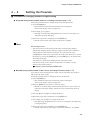
5 - 1
Function Setup
Follow the procedure below to set the functions such as event output type and external switch input assignments:
(1) Press the [DISP] key to display the integrated flowrate value.
>>"L" lamp lights.
(2) Keep the [<] key pressed for 3 seconds or longer.
>>"0.rMG" is indicated on the upper display. (Parameter setup mode)
(3) Keep the [<] key pressed for 3 seconds or longer.
>>The item No. C-0 1 is indicated on the upper display, and the function setup
mode is entered.
(4) Press the [ ] key or [V] key to select the target setup item No., and then press
the [ENT] key.
>>The current setting value being indicated on the display blinks.
(5) Press the [ ] key or [V] key to display the target setting value, and then press
the [ENT] key.
>>The setting value is stored.
v
v
If other items are required to set up, return to the step (4) and repeat the procedure.
Otherwise, proceed to the step (6).
(6) Press the [DISP] key.
>>The mode is returned to the instantaneous flowrate display.
Handling Precautions
• If any operation is not performed for one minute after entering the
function setup mode, the display automatically returns to the regular
display (instantaneous flowrate display).
• If the [DISP] key is pressed while the operation in step (5) is performed
(indicated by blinking display), the setting value remains at the previous
value without being updated.
5-2
Chapter 5. APPLICATION OPERATION
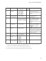
■ Function setup item list
Display Item
Item Description
Setup Item and
Description
Factory
Setting
Remarks
C-0 1
Key lock
0: Unlocked
1: Settings other than
flowrate setting are locked
2: All settings locked
0
The key lock can be canceled even
while it is enabled.
LOC is indicated on the display during
the key-locked setting.
C-02
Operating mode
selection (selection
by key operation)
0: Operating mode selection
by key operation is
disabled.
1: Operating mode selection
by key operation is
enabled.
1
The selection of whether operating
mode selection by key operation
(fully closed/control/fully open) is
"enabled" or "disabled", is available.
See 4-3 Selecting the Operating
Mode (page 4-6)
C-03
*1, *2
Instantaneous flow
-rate setup method
(instantaneous SP
setup method selection)
0: Digital setup (set by key
operation or RS-485
communications)
1: Analog setup (set by
external analog voltage
input)
0
C-04
Number of instanta- 0: Number of SPs = 1
neous flowrate setups
(SP-0 only)
selection (number
1: Number of SPs = 2
of SPs selection)
(SP-0, SP- 1)
2: Number of SPs = 3
(SP-0 to SP-2)
3: Number of SPs = 4
(SP-0 to SP-3)
0
C-05
*2
Input voltage range
selection, at analog
setting
(Analog SP input
range selection)
0: 0 to 5V input
1: 1 to 5V input
0
C-06
*2
Flowrate analog
output voltage
range selection
(PV analog output
range selection)
0: 0 to 5V output
1: 1 to 5V output
0
C-07
Event output 1 type
assignment
0: Not used (OFF at all times)
1: ON when alarm occurred
0
C-08
Event output 2 type
assignment
2: Integration pulse output
3: On when PV is in flowrate
OK judgement range
4: ON in control mode
5: ON in fully open mode
6: ON in control mode or
fully open mode
7: ON in fully closed mode
8: Instantaneous PV
upper limit event
9: Instantaneous PV
lower limit event 1
10:Instantaneous PV
lower limit event 2
11:Integrated flowrate event
-1 to -11: Reverse output of
1 to 11
(At no events: ON
At event occurred: OFF)
0
Flowrate OK judgment range,
upper/lower limit event flowrate,
integrated event flowrate and event
output delay time are set in the
parameter setup mode. See,
5-2 Parameter setup (page 5-7) for
the details. Note, the delay time
cannot be set to integration pulse
output.
9: Events are outputted even in
fully closed operation mode.
10:Events are not outputted in
fully closed operation mode.
-1 to -11: Always OFF during power
supply OFF.
5-3
Chapter 5. APPLICATION OPERATION
Display Item
Item Description
Setup Item and
Description
Factory
Setting
Remarks
C- 10
External switch input 1 0: Not used
function assignment 1: Reset integration
2: Stop integration count
operation
3: Switching of SP No.
0
3: To select an SP No. of 3 or more
setting, assign "3" both the C- 10
and C- 1 1.
4: The C-03 (analog / digital) setting
is reversed when the contact is
ON.
C- 1 1
External switch input 2 4: Switching of flowrate setup
function assignment
method
5: Valve fully closed
6: Valve fully open
7: Switching of slow start
operation
8: Switching of operating
mode
Contact ON: control mode
Contact OFF: fully closed
mode
0
7: “Slow start ON” must be selected
in C- 1 7.
5, 6, 8:
When the valve fully closed input
and the valve fully open input are
put in at the same time by two
contact, the both inputs are
disabled.
C- 13
Valve automatic
shut-off when the
integration event
occurred
0: Function disabled
1: Function enabled
0
When the integrated count value
reaches the integrated event setting
value, the valve is fully closed.
C- 14
Resetting the
integrated value
at start of control
0: Function disabled
1: Function enabled
0
When control is resumed from
the fully closed mode, the integrated
value is automatically reset.
C- 15
Flowrate alarm
setup type
0: Not used
1: Only upper limit alarm
used
2: Only lower limit alarm
used
3: Upper / lower limit alarm
used
3
Set the alarm flowrate in the
parameter setup mode.
See page 5-7.
C- 16
Operation selection
at alarm occurrence
0: Control continued
(alarm ignored)
1: Move to fully closed
2: Move to fully open
0
Alarm output turns ON even if “0”
is selected.
C- 1 7
Slow start setup
0: Slow start disabled
1 to 8: Slow start enabled
(equivalent to approx. 1
to 6 seconds settling time)
0
Slow start is enabled when the
external contact input turns ON,
in case of slow start operation
switching is selected at C- 10 to C- 1 1.
C- 18
Gas type selection
0: Conversion factor for
each gas type set by the
user
1: Air, nitrogen
3: Argon
4: Carbon dioxide (CO2)
1
If the flowrate range changes due to
a change in the gas type, the flowrate
OK range and flowrate alarm range in
the parameter setup must be changed.
When “0” is selected, set the
conversion factor in the parameter
setup mode.
C- 19
Flowrate display
0: Referenced to 20˚C,
1 atmosphere
1: Referenced to 0˚C,
1 atmosphere
2: Referenced to 25˚C,
1 atmosphere
3: Referenced to 35˚C,
1 atmosphere
0
5-4
Chapter 5. APPLICATION OPERATION
Display Item
Item Description
Setup Item and
Description
C-20
Inlet pressure
adjustment
0:
1:
2:
3:
4:
5:
C-2 1
Instantaneous
flowrate direct setup
function switching
C-23
0 to 0.1MPa
0.05 to 0.15MPa
0.15 to 0.25MPa
0.25 to 0.35MPa
0.35 to 0.45MPa
0.45 to 0.5MPa
Factory
Setting
Remarks
2
The accuracy drift caused by the
influence of pressure can be
compensated by adjusting the inlet
pressure setting to the actual inlet
pressure.
0: Function disabled
1: Function enabled
0
Can be controlled by
instantaneous SP being
change (blinking).
PV filter
0:
1:
2:
3:
0
If the PV filter is used in a
"2" or "3" setting, the operation
differential pressure must be lower
than the standard differential
pressure.
Do not change the setting under the
control.
C-28
*2
Analog optional
scaling function
0: Function disabled
1: Function enabled
0
The flowrate at analog input / output
100% (5V) can be optionally set.
The flowrate is set in parameter
setup mode.
See
page 5-7 for details.
C-29
PV forced zero
function
0: Function disabled
1: Function enabled
0
When the setting flowrate is zero, or
when the valve fully closed mode is
entered, the PV is forcibly made to
zero after delay time. The shifting of
PV by influence of pressure can be
cancelled. The delay time is set in the
parameter setup mode.
C-30
*3
Station address
setting
0: Communications
function disabled
1 to 127: Station address
0
C-3 1
*3
Transmission speed
selection
0:
1:
2:
3:
4:
0
C-32
*3
Communications
conditions selection
0: 8 data bits, even parity,
1 stop bit
1: 8 data bits, no parity,
2 stop bits
Without filter
Sampling 2 times moving-average
Sampling 4 times moving-average
Sampling 8 times moving-average
38400bps
19200bps
9600bps
4800bps
2400bps
0
*1: When "4: Switching of flowrate setup method" is selected at the external switch input function assignment
C- 10 or C- 1 1, the switching by external switch input takes precedence.
*2: These items can be set only on the models with analog input / output function.
*3: These items can be set only on the models with RS-485 communication function.
5-5
Chapter 5. APPLICATION OPERATION
5 - 2
Parameter Setup
● Setup method
Follow the procedure below to set the parameters such as flowrate deviation alarm
upper and lower limit flowrate and event output delay time.
(1) Press the [DISP] key to display the integrated flowrate.
>>"L" lamp lights.
(2) Keep the [<] key pressed for 3 seconds.
>>"0.rMG" is indicated on the upper display. Parameter setup mode is entered.
v
(3) Press the [ ] key or [V] key to select the target setup item, and press the [ENT]
key.
>> The setting value currently being indicated on the lower display blinks.
v
(4) Press the [ ] key or [V] key to select the target setting value. You can move to
the digit to be changed by pressing the [<] key.
(5) When the target setting value is displayed, press the [ENT] key to fix the
setting value.
>>The setting value is stored.
If other items are required to set up, return to the step (3) and repeat the procedure.
Otherwise, proceed to the step (6).
(6) Press the [DISP] key.
>>The mode is returned to the instantaneous flowrate display.
Handling Precautions
• If you do nothing for one minute after entering the parameter setup
mode, the display automatically returns to the regular (instantaneous
PV) display.
• If you press the [DISP] key without pressing the [ENT] key after carrying
out the operation in step (5), the setting remains at the previous value
without being updated.
5-6
Chapter 5. APPLICATION OPERATION
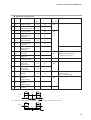
● Parameter setup item list
No. Display
Description
Factory
Setting Range
Setting
Referential
function setup
1
0.rMG
*1
Flowrate OK
judgment range
2
0.HyS
*1
Flowrate OK
(1% FS)
judgment hysteresis
*10
3
A. HI
*2, *3
Flowrate deviation
upper limit alarm
(10% FS) (0.5 to 100% FS) C-07,
*10
*10
C-08,
4
A.H.Hy
*2, *3
Flowrate deviation
upper limit alarm
hysteresis
(2% FS)
*10
5
A. LO
*2, *3
Flowrate deviation
lower limit alarm
(10% FS) (0.5 to 100% FS)
*10
*10
6 A.L.Hy
*2, *3
Flowrate deviation
lower limit alarm
hysteresis
(2% FS)
*10
A.dLy
*3
Flowrate deviation
alarm judgment
delay time
10.0s
1.0 to 999.9s
7
(0.5 to 100% FS) C-07,
*10
C-08
(2% FS)
*10
(0.5 to 100% FS) C- 15,
*10
C- 16
(0.5 to 100% FS)
*10
Event output 1
delay time
0.0s
0.0 to 999.9s
E.2.dL
*4
Event output 2
delay time
0.0s
0.0 to 999.9s
C.F.
10
*5
User setup
conversion factor
Unit: L / min(standard)
(0.5 to 100% FS)
*10
8 E. 1.dL
*4
9
Remarks
1.000
C-07,
C-08
Even if the delay time is set, it is
disabled during selection of
integration pulse output.
0.100 to 9.999
C- 18
C-07,
C-08
Unit: L / min(standard)
C-28
The flowrate of analog input / output
100% (5V) is set.
Unit: L / min(standard)
11 E. 1.SP
*6
Event output 1 upper (0% FS)
*10
/ lower limit
flowrate setup
(0 to 100% FS)
*10
12 E.2.SP
*6
Event output 2 upper (0% FS)
*10
/ lower limit
flowrate setup
(0 to 100% FS)
*10
13 A.SCL
*7
Analog optional
scaling
14 E.A.LO
*8
Integrated event
flowrate
(lower 4 digits)
0
0 to 9999
C-07,
C-08,
15 E.A.HI
*8
Integrated event
flowrate
(upper 4 digits)
0
0 to 9999
C- 13
16 P.0.dL
*9
PV forced zero
function
3.0s
0.0 to 999.9s
C-29
(100% FS) (10 to 100% FS)
*10
*10
*1: Operation during judgment of flowrate OK.
0.HyS
0.HyS
SP
ON(OK)
OFF
PV
0.rMG
0.rMG
*2: Operation during judgment of flowrate deviation upper and lower limit alarms.
A.L.Hy
A.H.Hy
ON(ALM)
SP
OFF
A.
Lo
A.
HI
PV
5-7
Chapter 5. APPLICATION OPERATION
*3: This can be set only when other than "0: Not used" is selected at the flowrate alarm setup type C- 15 in the
function setup.
*4: This can be set only when other than "0: Not used" is selected at the event output type assignment C-07 and
C-08 in the function setup.
*5: This can be set only when "0: User setting" is selected at gas type selection C- 18 in the function setup.
*6: This can be set only when "8: Instantaneous PV upper limit event, 9: Instantaneous PV lower limit event1 and
10: Instantaneous PV lower limit event 2" is selected for the C-07 and C-08 event output type assignment in
the function setup.
*7: This can be set only when "1: Function enabled" is selected for the C-28 analog optional scaling function in
the function setup.
*8: This can be set only when "11: Integrated flowrate event" is selected at the event output type assignment C-07
and C-08 in the function setup, or when "1: Function enabled" is selected at the valve automatic shut-off
function C- 13.
*9: This can be set only when "1: Function enabled" is selected at the PV forced zero function C-29 in the
function setup.
*10: The result of the factory setting and setting range becomes the flowrate obtained by multiplying the full scale
flowrate by the percentage in parentheses. (The factory setting and setting range vary according to the gas
type.)
5-8
Chapter 6.
TROUBLESHOOTING
■ Alarm code display
When a flowrate deviation alarm occurs or when an alarm occurs during controller
self-diagnostics, the operating mode currently selected at "Operation selection at
alarm occurrence" C- 16 in the function setup is forcibly switched to. (Except
AL7 1)
The upper display alternately indicates the alarm codes shown in the table below
and the regular display.
Alarm
code
Error
Cause
Countermeasure
AL0 1
Flowrate deviation lower
limit alarm
Insufficient alarm judgment delay time,
insufficient power voltage, insufficient
inlet pressure, excessive operating
temperature, etc.
Request for repair service
if there is no problem on the items
listed on the left.
AL02
Flowrate deviation
upper limit alarm
Insufficient alarm judgment delay time,
valve trouble, sensor trouble, etc.
Request for repair service
if there is no problem with the
delay time.
AL7 1
Valve overheat prevention
limit is operated
During the control or fully-open mode,
the gas is forcibly shut-off by external
device for more than 5 minutes.
When the gas is continuously
shut off by external device, set
the set flowrate to zero or valve
fully-closed mode.
AL8 1
Sensor error
Sensor trouble, foreign object attached
to sensor, or entering of hydrogen or
helium gas.
If sensor is not restored after
turning the power OFF, then
request for repair service.
AL9 1
I/O correction data error
Data corrupted due to electrical noise.
Request for repair service.
AL92
Sensor calibration data error Data corrupted due to electrical noise.
Request for repair service.
AL93
User setup data error
Set data again.
Power shutoff during writing of data.
Handling Precautions
• The alarm code is displayed only when the instantaneous flowrate,
operating mode and integrated flowrate are displayed.
• AL7 1(Valve overheat prevention limit) is operated only for the MPC0020.
In this case, in spite of the selection at C- 16 in the function setup, the
valve drive current is forcibly limited. If this state is continued for 30
minutes or longer, the valve is fully closed.
• If AL8 1(sensor error) occurs, the flowrate value will become indefinite.
Therefore, the control flowrate becomes indefinite even if "0: Control
continued (alarm ignored)" is selected at C- 16 in the function setup.
• When "1: Move to fully closed" or "2: Move to fully open" is selected at
C- 16 in the function setup, the alarm display and the operating mode at
alarm occurrence can be maintained even after the cause of alarm is
removed. When canceling the alarm, make the alarm reset operation.
● Canceling the alarm
Keep the [ENT] key pressed while the instantaneous flowrate is displayed.
The alarm can be cancelled after 3 seconds.
6-1
Chapter 6. TROUBLESHOOTING
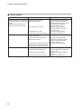
■ Other troubles
Error
Cause
Flowrate display does not become • Zero point shift due to the
zero even in spite of an actual zero influence of pressure.
flowrate
(Display does not become OFF
even if the valve is fully closed.)
• Gas type setup is incorrect.
• Condensation on sensor.
• Foreign object attached to sensor.
Flowrate does not stabilize.
Countermeasure
• Match the inlet pressure setting
(function setup C-20) with the
actual inlet pressure used, or use
the PV forced zero function
(function setup C-29).
• Match the gas type setting
(function setup C- 18) with the
actual gas used.
• Insert a mist trap upstream.
• Request for repair service.
• Operation differential pressure
range is exceeded.
• Large inlet pressure fluctuations.
• Regulator interference.
• Reduce the inlet pressure.
• Temperature reference does not
match the reference flowmeter.
• Match the temperature reference.
(Can be changed in the function
setup C- 19)
• Change the regulator pressure
setting.
• Request for repair service.
• Install a regulator upstream.
• Change the regulator pressure
setting or apply the PV filter.
(function setup C-23)
• Large pressure loss between regulator • Increase the pipe diameter.
and this device. (Large fluctuation in
inlet pressure according to flowrate.)
Poor accuracy
• Regulator is vibrating slightly.
• Foreign object attached to sensor.
6-2
Chapter 7.
SPECIFICATIONS
■ Specifications
Specifications are given on the next page.
7-1
Chapter 7. SPECIFICATIONS
Model No.
Item
Valve type
MPC9500
MPC0002
Proportional solenoid valve
Valve operation
Normally closed when de-energized (N.C.)
Standard full-scale flowrate
(nitrogen conversionvalue) *1
0.500 L/min(standard)
Standard compatible gas types
Nitrogen/air, argon, carbon dioxide (CO2)
Note; The gas must be a dry gas not containing corrosive
components (chlorine, sulfur, acid).
The gas must also be a clean gas not containing dust or oil mist.
Control
Control range *1
4 to 100%FS (
Response
Within 1.0s (typ) to set point ±2%FS
Accuracy
±2%FS max. (at standard temperature and differential pressure)
Repeatability
±1%FS max.
Temperature influence
Within 0.1%FS/°C [0.056%FS/°F]
Pressure influence Q≥40%FS
0.7%FSmax.
0.4%FSmax.
(per 0.1MPa
10%FS≤Q<40%FS 1.2%FSmax.
0.7%FSmax.
Q: flowrate)
Q<10%FS
1.2%FSmax.
Pressure Standard differential pressure *2
2.00 L/min(standard)
*1)
2%FSmax.
0.2MPa [290PSI] (Inlet pressure:0.2MPa [290PSI] (gauge),
outlet pressure: 0.0MPa [0PSI] (gauge))
Required differential pressure *3
0.05MPa [72.5PSI]
Operating differential pressure
range *4
0.3MPa [435PSI] max.
Pressure resistance
0.5MPa [725PSI] (gauge)
Tempera- Standard operating temperature *2
25°C [77°F]
ture
Allowable operating temperature
range
-10 to +50°C [14 to 122°F]
(0 to 50°C [32 to 122°F] when RS-485 communication)
Allowable storage temperature range
-10 to +60°C [14 to 140°F]
Humidity Allowable operating humidity range
10 to 90%RH(no condensation allowed)
Flowrate Setup method
setup
(1)Key operation (2)External setup voltage input (only for the
model with analog I/O function) (3)Loader communication
(4)communications (only for the model RS-485 communications
function)
Setup resolution
Setup input voltage range
Flowrate Display method
display
Indication resolution
Indication accuracy
*1
0 to 5Vdc/1 to 5Vdc (selectable by function setup, and external
input (only for the model with analog I/O function))
7-segment LED 8 digits
(For the instantaneous flowrate display: 4 digits and for the
setting flowrate display:4 digits)
*1
±2%FS ±1 digit
(at standard temperature and differential pressure)
Integra-
Indication range
0.00 to 999,999.99L
0.0 to 9,999,999.9L
tion
Indication resolution
0.01L
0.1L
function
Data backup timing
(1)At each 5L count
(1)At each 20L count
(2)At each after 1 hour from the previous backup
Flowrate Output scale
0 to full-scale flowrate (scaling available)
output
0 to 5Vdc/1 to 5Vdc
(selectable by function setup and external input)
7-2
Standard output voltage range
Chapter 7. SPECIFICATIONS
MPC0005
MPC0020
Proportional solenoid valve
Normally closed when de-energized (N.C.)
5.00 L/min(standard)
20.0 L/min(standard)
Nitrogen/air, argon, carbon dioxide (CO2)
Note; The gas must be a dry gas not containing corrosive
components (chlorine, sulfur, acid).
The gas must also be a clean gas not containing dust or oil mist.
2 to 100%FS (
*1)
Within 1.0s (typ) to set point ±2%FS
±2%FS max. (at standard temperature and differential pressure)
±1%FS max.
Within 0.1%FS/°C [0.056%FS/°F]
0.2 %FS max.
0.2 %FS max.
0.3 %FS max.
0.2 %FS max.
0.5 %FS max.
0.2 %FS max.
0.2MPa [290PSI] (Inlet pressure:0.2MPa [290PSI] (gauge),
Outlet pressure: 0.0MPa [0PSI] (gauge))
0.1MPa [145PSI]
0.15MPa [217.5PSI]
0.3MPa [435PSI] max.
0.05 to 0.3MPa [72.5 to 435PSI]
0.5MPa [725PSI] (gauge)
25°C [77°F]
-10 to +50°C [14 to 122°F]
(0 to 50°C [32 to 122°F] when RS-485 communication)
-10 to +60°C [14 to 140°F]
10 to 90%RH(no condensation allowed)
(1)Key operation (2)External setup voltage input (only for the
model with analog I/O function) (3)Loader communication
(4)communications (only for the model RS-485 communications
function)
*1
0 to 5Vdc/1 to 5Vdc (selectable by function setup, and external
input (only for the model with analog I/O function))
7-segment LED 8 digits
(For the instantaneous flowrate display: 4 digits and for the
setting flowrate display:4 digits)
*1
±2%FS ±1 digit
(at standard temperature and differential pressure)
0.0 to 9,999,999.9L
0 to 99,999,999L
0.1L
1L
(1)At each 50L count
(1)At each 200L count
(2)At each after 1 hour from the previous backup
0 to full-scale flowrate (scaling available)
0 to 5Vdc/1 to 5Vdc
(selectable by function setup and external input)
7-3
Chapter 7. SPECIFICATIONS
Model No.
Item
MPC9500
MPC0002
Flowrate
Max. output voltage
7Vdc max. (maximum output when flowrate exceeds range)
output
Accuracy
±0.5%FS
(The input impedance of the connected device must be at least
100kΩ.)
Total output accuracy: Indication accuracy ±0.5%FS
Event
Number of outputs
2 points
output
Output rating
30Vdc 15mA max. (open collector non-insulated output)
Integrated pulse output width
100ms±10% (when the integrated pulse output is selected.)
Integrated pulse rate
0.01L/pulse
External
Number of inputs
2 points
switch
Circuit type
Non-voltage contact or open collector
input
Contact OFF terminal voltage
2.0±0.5V
Contact ON terminal current
Approx. 0.5mA (contact current)
Allowable ON contact resistance
Max. 250Ω
Allowable OFF contact resistance
Min. 100kΩ
Allowable ON residual voltage
Max. 1.0V (with open collector)
0.1L/pulse
Allowable OFF leakage current
Max. 50µA (with open collector)
Communi-
System
(1)Loader communication *6 (2)RS-485 communications(3-wire) *7
cation
Transmission speed
2400, 4800, 9600, 19200, 38400bps
Power
Rating
24Vdc, current consumption 300mA max.
supply
Allowable voltage range
22.8 to 25.4Vdc (ripple 5% max.)
Material of gas-contacting parts
Brass(Ni plated), stainless steel, Teflon, Viton
Connection method
Rc1/8
Mounting direction
Display surface must be placed vertically (inlet port: lower side,
outlet port: upper side)
Mass
Approx. 300g
Accessories
Mounting bracket (81446917-001), wiring connector
Applicable standard
EN61326: 1997, Amendment A1: 1998 / A2: 2001
*1:
L/min(standard) indicates the volume flowrate per minute (L/min) converted to 20˚C and 1 atmospheric
pressure. The reference temperature can also be changed to 0˚C, 25˚C and 35˚C. The controllable flowrate
range varies according to the gas type. Refer to the following table:
MPC9500
MPC0002
Control flowrate range Setting/indication resolution Control flowrate range Setting/indication resolution
L / min(standard)
L / min(standard)
L / min(standard)
L / min(standard)
Nitrogen / air
0.020 to 0.500
0.002
0.08 to 2.00
0.01
Argon
0.020 to 0.500
0.002
0.08 to 2.00
0.01
Carbon dioxide
0.012 to 0.300
0.001
0.040 to 1.200
0.005
MPC0005
MPC0020
Control flowrate range Setting/indication resolution Control flowrate range Setting/indication resolution
L / min(standard)
L / min(standard)
L / min(standard)
L / min(standard)
Nitrogen / air
0.10 to 5.00
0.02
0.4 to 20.0
0.1
Argon
0.10 to 0.50
0.02
0.4 to 20.0
0.1
Carbon dioxide
0.06 to 3.00
0.01
0.3 to 16.0
0.1
7-4
Chapter 7. SPECIFICATIONS
MPC0005
MPC0020
7Vdc max. (maximum output when flowrate exceeds range)
±0.5%FS
(The input impedance of the connected device must be at least
100kΩ.)
Total output accuracy: Indication accuracy ±0.5%FS
2 points
30Vdc 15mA max. (open collector non-insulated output)
100ms±10% (when the integrated pulse output is selected.)
0.1L/pulse
1L/pulse
2 points
Non-voltage contact or open collector
2.0±0.5V
Approx. 0.5mA (contact current)
Max. 250Ω
Min. 100kΩ
Max. 1.0V (with open collector)
Max. 50µA (with open collector)
(1)Loader communication *6 (2)RS-485 communications(3-wire) *7
2400, 4800, 9600, 19200, 38400bps
24Vdc, current consumption 300mA max.
22.8 to 25.4Vdc (ripple 5% max.)
Brass(Ni plated), stainless steel, Teflon, Viton
Rc1/8
Display surface must be placed vertically (inlet port: lower side,
outlet port: upper side)
Approx. 300g
Mounting bracket (81446917-001), wiring connector
EN61326: 1997, Amendment A1: 1998 / A2: 2001
*2:
*3:
*4:
*5:
*6:
*7:
The temperature and pressure at calibration.
Differential pressure required for obtaining full-scale flowrate.
Operation is possible even under the required differential pressure. However, the controllable flowrate range
will become small. For details, refer to;
■ Relationship between flowrate when valve is fully open and differential pressure (next page).
Applicable only to the model with analog input/output function.
A dedicated loader package (sold separately) is required.
Applicable only to the model with RS-485 communications function.
7-5
Chapter 7. SPECIFICATIONS
MPC9500
20
10
0.1
0.2 0.3 0.4 0.5
Flowrate (L/min(standard))
MPC9500
2.9
1.45
0.1
40
20
1
2
3
4
5
Flowrate (L/min(standard))
0.2 0.3 0.4 0.5
Flowrate (L/min(standard))
0.6
6
11.6
8.7
5.8
2.9
0
0
1
2
3
4
5
Flowrate (L/min(standard))
80
40
0
0
4
8
12
16
20
24
Flowrate (L/min(standard))
MPC0002 / 0005
14.5
4.35
0
0
120
60
Differential pressure (PSI)
5.8
80
0
0
0.6
MPC0020
160
Differential pressure (kPa)
30
0
0
MPC0002 / 0005
100
Differential pressure (kPa)
40
Differential pressure (PSI)
Differential pressure (PSI)
Differential pressure (kPa)
■ Relationship between flowrate when valve is fully open and differential pressure
(in air)
6
MPC0020
23.2
17.4
11.6
5.8
0
0
4
8
12
16
20
24
Flowrate (L/min(standard))
Calculate the differential pressure from the following formula when a gas other
than air is used:
Differential pressure
= differential pressure in air X specific gravity of gas to be controlled
Example) The differential pressure when argon flows at
10L/min (standard) on MPC0020 is:
35kPa X 1.38 = 48kPa (5.075PSI X 1.38 = 7.004PSI)
Specific Gravity of Standard Compatible Gas (air is taken as 1.0)
Argon = 1.38
Carbon dioxide = 1.53
7-6
Revision History
Printed
Date
Manual Number
Edition
04-02
CP-SP-1153E 1st Edition
Revised pages
Description
Specifications are subject to change without notice.
Advanced Automation Company
International Business Headquarters
Totate International Building
2-12-19 Shibuya Shibuya-ku
Tokyo 150-8316 Japan
URL: http://www.yamatake.com
This has been printed on recycled paper.
(01)
Printed in Japan.
1st Edition: Issued in Feb., 2004(W)