1
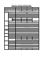
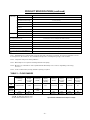
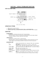
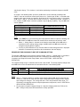
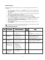
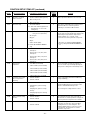
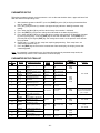
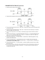
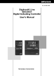
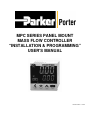
MPC SERIES PANEL MOUNT
MASS FLOW CONTROLLER
“INSTALLATION & PROGRAMMING”
USER’S MANUAL
FM-1038 Rev. 0 4/08
TABLE OF CONTENTS
SAFETY PRECAUTIONS .................................................................................................................1
Section 1 – INTRODUCTION............................................................................................................2
Preface ...................................................................................................................... 2
Features .................................................................................................................... 2
Functions ................................................................................................................... 3
Model Selection Guide .............................................................................................. 4
Section 2 – PRODUCT SPECIFICATIONS ..................................................................................... 5
Section 3 – DISPLAY TERMS AND FUNCTIONS........................................................................... 7
Display (Front View) .................................................................................................. 7
Definition of Terms .................................................................................................... 7
Functions ................................................................................................................... 7
Rear View .................................................................................................................. 8
Section 4 – MOUNTING AND WIRING ........................................................................................... 9
Location ..................................................................................................................... 9
Dimensional Data ...................................................................................................... 9
Mounting Procedure .................................................................................................. 9
External Electrical Connections .............................................................................. 11
Section 5 – BASIC OPERATION ................................................................................................... 13
Switching Displays .................................................................................................. 13
Setting the Flow Rate .............................................................................................. 15
Selecting the Operation Mode................................................................................. 17
Section 6 – APPLICATION OPERATION ...................................................................................... 18
Function Setup ........................................................................................................ 19
Function Setup Item List.......................................................................................... 19
Parameter Setup ..................................................................................................... 22
Parameter Setup Item List....................................................................................... 22
Section 7 – TROUBLESHOOTING................................................................................................ 24
Alarm Code Display................................................................................................. 24
Miscellaneous Errors............................................................................................... 25
Section 8 – POLICIES AND CERTIFICATE OF WARRANTY ...................................................... 26
Policies .................................................................................................................... 26
Certificate of Warranty............................................................................................. 27
SAFETY PRECAUTIONS
WARNING
Warnings are indicated when mishandling this product might result in death or serious injury to the user.
CAUTION
Cautions are indicated when mishandling this product might result in minor injury to the user or only
physical damage to this product.
WARNING
Never allow gases within explosive limits to pass through the MPC Series Panel Mount Mass
Flow Controller (MFC). Doing so may result in an explosion.
Do not use the MPC Series Panel Mount MFC for gases other than compatible gas types.
CAUTION
Prevent foreign materials from entering the MPC Series Panel Mount MFC. If foreign materials
are introduced to the MFC, measurement error may occur and result in damaging the MFC. To
eliminate contamination from foreign materials, start-up cleaning is highly recommended prior to
MFC installation. Start-up cleaning must remove weld debris, tube scale and any loose
particulate generated during system fabrication. Install an upstream filter and periodically inspect
the filter.
Do not allow foreign materials to enter the MFC housing. Failure to do so may result in
malfunction or faulty operation.
Use the MPC Series Panel Mount MFC within the operating differential pressure range. Do not
exceed the maximum allowable operating pressure.
The control valve in the MPC Series Panel Mount MFC does not offer positive shut-off. If positive
shut-off is a system requirement, install a separate shut-off valve. When a separate shut-off
valve is closed, the user must command the MFC control valve fully closed by one of the
following methods:
Establish a zero setpoint signal.
Set the operation mode to the fully closed mode.
If the MFC’s control valve is maintained in the control mode despite closing the separate shut-off
valve (resulting in no flow through the MFC), a flow surge will occur upon opening of the shut-off
valve. With Model MPC20, if the separate shut-off valve is closed for more than five (5) minutes
while in the control mode or the valve is forced full open, the valve overheat limit (‘AL71’) is
activated and the valve driving current is limited. If this status exists for greater than 30 minutes,
the valve is forced to a fully closed condition.
When the MPC Series Panel Mount MFC is panel-mounted, use tubing that does not stress the
MFC housing. If metal piping is directly connected to the 1/8” FNPT connector of the MFC, the
housing could be damaged.
The MPC Series Panel Mount MFC’s power supply circuitry and the input/output circuitry are not
isolated. Ensure the MFC’s power supply is isolated from the power supply for external devices.
If a common power supply is used for both the MFC and the external devices, MFC malfunction
or faulty operation may occur.
Do not supply a negative setpoint voltage or a setpoint voltage greater than 5 Vdc to the MFC.
Doing so may cause MFC malfunction or faulty operation.
A surge suppressor is recommended should power spikes occur.
-1-
SECTION 1 – INTRODUCTION
PREFACE
Thank you for purchasing Porter’s MPC Series Panel Mount Mass Flow Controller (MFC). Please keep
this user’s manual available for future reference. Before operating the MPC Series Panel Mount MFC,
please note the safety precautions (warnings and cautions). It is recommended these instructions be
read and understood before performing any operation. Failure to do so could result in serious injury
and/or damage to the equipment.
This “Installation & Programming” user’s manual explains the handling precautions, specifications,
installation, start-up, programming, maintenance, and troubleshooting of your MPC Series Panel Mount
MFC. The “Installation & Programming” user’s manual also contains information on the various functions
of the MPC Series Panel Mount MFC. For basic instructions on how to use this product, refer to the MPC
Series Panel Mount MFC “Quick-Start” user’s manual # FM-1032. A copy of user’s manual # FM-1032 is
included with every MPC Series Panel Mount MFC.
When unpacking the MPC Series Panel Mount MFC, confirm the following components were received.
The original shipping container in which your MPC Series Panel Mount MFC was received should not be
discarded in case reshipment is necessary.
COMPONENT
MPC Series Panel Mount MFC
Mounting Bracket
Mating Electrical Connector
User’s Manual # FM-1032
QUANTITY
One (1)
One (1)
One (1)
One (1)
FEATURES
The MPC Series Panel Mount MFC is a mass flow controller featuring high performance in a
compact package design. Integrating the advanced technologies of an ultra-high speed response
thermal flow velocity sensor, a sensor assembly made utilizing proprietary technology, a
miniature proportional solenoid valve, a new flow channel system and advanced actuator control
technology achieves the realization of the MFC which has panel-mount capabilities.
The MPC Series Panel Mount MFC is a compact (1.89 x 1.89 inches [48 x 48 mm] front panel
size) and lightweight (approximately 10.6 ounces [300 grams]) MFC.
A wide variety of functions are provided as a standard features to satisfy the various user needs.
Simple mounting and operation make the MPC Series Panel Mount MFC a viable option when
replacing from a variable-area (i.e. float and glass tube-type) flowmeter. In addition, the
automatic control of flow rate and remote setting value change can be performed.
The effects of temperature and pressure fluctuations are negligible when compared to a variablearea flowmeter.
With a variable-area flowmeter, pressure and temperature compensation is inevitable.
Additionally, if the original sizing conditions (i.e. specific gravity, operating temperature or
operating pressure) are different from the actual operating conditions, the indicated flow rate must
be corrected to compensate for the change in operating parameters. Since the MPC Series
Panel Mount MFC controls mass flow, these corrections are not necessary.
-2-
FUNCTIONS
MULTI-SETTING FUNCTION
Up to four (4) preset flow rate settings can be instantaneously switched to by key operation or
external switching input.
GAS TYPE SWITCHING FUNCTION
The gas type to be used can be selected from the standard compatible gases by key operation.
GAS TYPE SETTING FUNCTION
The user can set conversion factors for any gas type, including mixed gases, to accommodate
gases other than standard compatible gases.
VALVE FULL OPEN/FULL CLOSE FUNCTION (SELECTING THE OPERATION MODE)
The valve can be driven fully opened or fully closed by key operation or external switching input.
SLOW START FUNCTION
Sudden changes in the controlled flow rate, when control is initiated or when the flow rate setting
value is changed, can be suppressed. The control speed can be changed in eight (8) stages
within the range from approximately 1 to 6 seconds.
FLOW RATE TOTALIZATION FUNCTION
The flow rate can be totalized up to eight (8) digits (99,999,999 counts) (the display is switched in
four [4] digits at a time). The display resolution is:
Model MPC95:............................... 0.01L
Models MPC02 and MPC05: ......... 0.1L
Model MPC20:............................... 1L
The count can be reset by key operation or external switching input. Totalization start/stop/reset
can be remote-controlled by external switching input.
After a reset-by-key operation, the totalization calculation is started automatically. However, if a
reset (contact ON) is carried out by external switching input, totalization is resumed by the contact
turning OFF.
VALVE DRIVE OUTPUT DISPLAY
The valve drive output can be displayed as a range of 0.0 to 100.0%. This allows detection of
supply pressure fluctuations and excessive pressure drop due to piping restrictions.
ALARM DISPLAY/OUTPUT/SHUT-OFF
The flow rate deviation alarm can be output by detecting the deviation between setting flow rate
and controlled flow rate. The alarm judgment delay time can also be programmed. When a flow
rate alarm occurs or an alarm occurs during MFC self-diagnostics, the event signal is output and,
at the user’s option, the valve can be driven fully closed or fully opened.
EVENT LAMP LIGHTING/OUTPUT
Two (2) of the following event types can be output:
Alarm output (when the flow rate deviation alarm or self-diagnostics occurs).
Flow rate upper/lower limit output (output by comparison to the optional upper/lower flow
rate limit setting value).
Totalization count up output (when the totalization setting flow rate is exceeded).
Totalization pulse output (pulse can be output for each totalization display unit).
‘OK’ output (when the control flow rate is within the range of "setpoint ± allowable range").
-3-
The operating mode can be identified and output externally as an event.
The output ON delay time can also be programmed. However, the delay cannot be set to
totalization pulse output. In addition, the output logic can be reversed (during normal operation:
ON; at event occurrence: OFF). However, the output is always OFF when power is off.
‘OK’ LAMP LIGHTING/OUTPUT
The ‘OK’ lamp can be made to light when the controlled flow rate is within the “setting value ±
allowable range”. This function is beneficial for visual verification whether or not the new setting
value is being followed properly when a setting value is changed. The ‘OK’ lamp output can also
be used as an interlock signal for subsequent processes by assigning it to an event output and
loading it to a sequence program.
AUTOMATIC SHUT-OFF FUNCTION
The valve can be automatically closed under the following conditions:
When the totalization count value reaches the setting value.
When one of the alarms, including flow rate alarms, occurs.
Please note the control valve in the MPC Series Panel Mount MFC does not offer positive shutoff. If positive shut-off is a system requirement, install a separate shut-off valve.
AUTOMATIC RESET OF TOTALIZATION COUNT AT START OF CONTROL FUNCTION
Start of control and totalization count reset can be carried out simultaneously by a single action
(key operation or external switching input). Combining this function with the automatic shut-off
function described above is handy for shutting the valve off when a fixed number of totalization
values have been counted repeatedly.
DIRECT SETUP FUNCTION
Allows users to easily change the flow rate setup. This function is useful when you frequently
change setting values, for example, when you adjust the preset flow rate during trial operation.
LOADER COMMUNICATION FUNCTION
The connection of a dedicated loader cable (available separately) to the loader jack on the rear of
the MFC enables direct communication with a personal computer in the form of one-to-one using
the user-supplied communication program. By using this loader communication, various settings
in the function setup and the flow rate setup can be configured from a personal computer. The
controlled flow rate or alarm status can be observed with the personal computer.
MODEL SELECTION GUIDE
MODEL NUMBER
MPC95-BBNSP1
MPC02-BBNSP1
MPC02-BBNHP1
MPC05-BBNSP1
MPC20-BBNSP1
FLOW RANGE
0.02-0.5 SLPM Nitrogen
0.08-2.0 SLPM Nitrogen
0.08-2.0 SLPM Helium
0.1-5.0 SLPM Nitrogen
0.4-20 SLPM Nitrogen
-4-
SECTION 2 – PRODUCT SPECIFICATIONS
Model Number
MPC02
MPC95
Control Valve Type
2.0 SLPM (N2 or Helium)
0.5 SLPM
Rangeability (Control Range)
(Refer to Table 1)
25:1 (4-100% full scale [FS])
Response Time
50:1 (2-100% FS)
±2% FS (at 20°C and 30 PSIG)
Repeatability
±1% FS
Temperature Coefficient
Pressure
Flow ≥40% FS
Coefficient (Per
Flow ≥10% FS
14.5 PSI)
Flow <40% FS
Flow <10% FS
Minimum Differential Pressure
(Note 3)
Maximum Differential Pressure
(Note 4)
±0.1% FS/°C (±0.056% FS/°F)
0.7% FS
0.4% FS
0.2% FS
1.2% FS
0.7% FS
0.3% FS
2% FS
1.2% FS
0.5% FS
7 PSIG
7 PSIG
14.5 PSIG
22 PSIG
40 PSIG
Calibration Pressure (Note 2)
30 PSIG (Inlet pressure: 30 PSIG and outlet pressure: 0 PSIG)
75 PSIG
Calibration Temperature (Note 2)
20°C
Operating Temperature Range
-10 to 50°C (14 to 122°F)
Storage Temperature Range
-10 to 60°C (14 to 140°F)
Operating Humidity Range
Setpoint
Setpoint Input
10 to 90% Relative Humidity (non-condensing)
Keypad Operation or External Setpoint Voltage Input
Resolution
Refer to Table 1
Setpoint Input Voltage
Totalizer
Function
0.2% FS
Maximum Operating Pressure
Humidity
Flow Rate
Indication
20 SLPM
1.0 second to within ±2% FS of setpoint (typical)
Accuracy
Temperature
5.0 SLPM
Nitrogen/air, oxygen, argon, carbon dioxide (all models except Model MPC02-BBNHP1);
Helium (Model MPC02-BBNHP1 only) - Gas must be dry, clean and oil-free.
Compatible Gases
Pressure
MPC20
Normally closed proportional solenoid valve
Maximum Flow Capacity (N2 unless otherwise
noted) (Note 1)
Control
MPC05
Display Type
0 to 5 Vdc or 1 to 5 Vdc (selectable)
7-segment LED; 8 digits (Instantaneous flow rate display: 4 digits; Setpoint flow rate display: 4 digits)
Display Resolution
Refer to Table 1
Indication Accuracy
±2% FS ±1 digit
Display Range
Display Resolution
Totalizer Backup Timing
0.00 to 999,999.99L
0.0 to 9,999,999.9L
0.0 to 9,999,999.9L
0 to 99,999,999L
0.01L
0.1L
0.1L
1L
Every 5L count
Every 20L count
Every 50L count
Every 200L count
Every hour (time) from the previous backup
Flow Rate
Output
Output Scale
0 to full scale flow rate (scaling selectable)
Output Signal Voltage
Maximum Output Signal Voltage
Accuracy
Event Output
0 to 5 Vdc or 1 to 5 Vdc (selectable)
7 Vdc maximum (maximum output signal when flow rate exceeds maximum flow capacity)
±0.5% FS (Input impedance of the connected device must be 100k ohms or greater).
Overall output accuracy: Indication accuracy ±0.5% FS
Number of Outputs
2
Output Rating
30 Vdc, 15 mAdc maximum (Open collector non-isolated output)
Totalizer Pulse Output Width
Totalizer Pulse Output Rate
100 ms (±10%) (when totalizer pulse output is selected)
0.01L/pulse
0.1L/pulse
-5-
0.1L/pulse
1L/pulse
PRODUCT SPECIFICATIONS (continued)
External
Contact Input
Number of Inputs
2
Input Type
Potential-free contact or open collector
Contact OFF Terminal Voltage
2.0 Vdc (±0.5Vdc)
Contact ON Terminal Current
Approx. 0.5 mAdc (contact current)
Allowable ON Contact Resistance
250 ohms maximum
Allowable OFF Contact
Resistance
100k ohms minimum
Allowable ON Residual Voltage
1.0 Vdc maximum (with open collector)
Allowable OFF Leakage Current
50 µAdc maximum (with open collector)
Communication System (Note 5)
Loader communication (dedicated cable required)
Transmission Speed
19200 bps
Power Supply Requirements
24 Vdc (±5%); current consumption 300 mAdc maximum
Materials of Construction
Brass (nickel-plated), stainless steel, Teflon®, Viton®
Process Connections
1/8” FNPT
Mounting Orientation
Housing horizontal with inlet & outlet ports vertically oriented (‘IN’ - bottom & ‘OUT’ - top)
Weight (Approximate)
10.6 oz. (300 grams)
Applicable Standard
CENELEC # EN61326: 1997; Amendment A1: 1998; Amendment A2: 2000
Accessory Components (Included With Every
MFC)
Mounting bracket and mating electrical connector
Note 1: SLPM indicates the volumetric flow corrected to 20°C and 1 atmosphere (14.7 PSIA). The reference temperature can also
be changed to 0°C, 25°C and 35°C. The controllable flow range varies according to the gas type. Refer to Table 1.
Note 2: Temperature and pressure during calibration.
Note 3: Differential pressure required for obtaining maximum flow capacity.
Note 4: Operation is possible with less than required minimum differential pressure, however, rangeability (control range)
decreases.
Note 5: Loader communications package (available separately) is required.
TABLE 1 – FLOW RANGES
MPC95
Nitrogen
/Air
Oxygen
Argon
Carbon
Dioxide
Helium
MPC02
Setpoint/
Flow Range
Display
Resolution
(SLPM)
(SLPM)
MPC05
Setpoint/
Flow Range
Display
Resolution
(SLPM)
(SLPM)
MPC20
Setpoint/
Flow Range
Display
Resolution
(SLPM)
(SLPM)
Flow Range
(SLPM)
Setpoint/
Display
Resolution
(SLPM)
0.020 to 0.500
0.002
0.08 to 2.00
0.01
0.10 to 5.00
0.02
0.4 to 20.0
0.1
0.012 to 0.300
0.001
0.040 to
1.200
0.005
0.06 to 3.00
0.01
0.3 to 16.0
0.1
Not
Applicable
Not
Applicable
0.08 to 2.00
0.01
Not
Applicable
Not
Applicable
Not
Applicable
Not
Applicable
Teflon® - E.I. DuPont de Nemours & Co.
Viton® - DuPont Dow Elastomers L.L.C.
Specifications and dimensions subject to change
-6-
SECTION 3 – DISPLAY TERMS AND FUNCTIONS
DISPLAY (FRONT VIEW)
DEFINITION OF TERMS
SP (Setpoint): Set flow rate value.
PV (Process Variable): Instantaneous flow rate value (i.e. controlled flow rate).
Operation mode: Three (3) modes of ‘Valve Fully Closed’/’Valve Control’/’Valve Fully Open’.
FUNCTIONS
UPPER DISPLAY
Displays the instantaneous flow rate value (7-segment display).
When the display is switched, also displays the totalized flow rate value (upper 4 digits),
parameter setup item, function setup item or alarm details.
LOWER DISPLAY
Displays the set flow rate value (7-segment display).
When the display is switched, also displays the operation mode, totalized flow rate value
(lower 4 digits), valve drive output, parameter setup values or function setup values.
OPERATION LAMP
‘L’:
‘OK’:
‘SP1’ to ‘SP3’:
‘EV1’ & ‘EV2’:
[DISP] key:
[<], [∨
∨] & [∧
∧] keys:
[ENT] key:
Indicates the totalized flow rate is displayed. Blinks when a totalization
event occurs.
Lights when the controlled flow rate is within the “setting value ±
allowable range”. Blinks when the operating mode is ‘Valve Fully Open’.
The lamp corresponding to the SP number that is used at multi-setting is
lit.
Lights when the event output is ON.
Used when switching the details of the display.
Used when incrementing/decrementing the digit or moving to a desired
digit.
Used when setting the SP value and storing the value. This key may
also be used for the totalized flow rate resetting and alarm resetting.
-7-
REAR VIEW
LOADER JACK:
The connection of a dedicated loader cable (available separately) to the
loader jack on the rear of the MFC enables direct communication with a
personal computer.
‘IN’ CONNECTOR:
1/8” FNPT inlet connector.
‘OUT’ CONNECTOR:
1/8” FNPT outlet connector.
-8-
SECTION 4 – MOUNTING AND WIRING
LOCATION
Avoid mounting the MPC Series Panel Mount MFC in locations subject to:
High and low temperature and humidity.
Sudden changes in temperature and condensation.
Corrosive and/or flammable gas-containing environments.
Environments containing high amounts of dirt, dust, salt, conductive substances (e.g. metal particles,
water, oil mist, etc.) and organic solvents.
Mechanical shock or vibration.
Direct sunlight or precipitation.
Splashing of oil or chemicals.
Sources of electrical interference and magnetic fields.
DIMENSIONAL DATA
MOUNTING PROCEDURE
PROCESS CONNECTION INSTALLATION
While installing the inlet and outlet process connections to the inlet and outlet 1/8” FNPT connectors,
do not hold the housing of the MPC Series Panel Mount MFC. Doing so may damage the MFC.
Inspect the process connections for any dirt or particulate matter. Apply an appropriate amount of
thread sealant to the 1/8” MNPT threads of both process connections.
Using a 14 mm wrench to secure the inlet and outlet 1/8” FNPT connectors and an appropriate size
wrench for the process connections, install each process connection according to the applicable
process connection manufacturer’s specific recommendations regarding installation and tightening.
Overtightening the process connections will damage the 1/8” FNPT connectors.
-9-
PANEL MOUNTING
To panel-mount the MPC Series Panel Mount MFC, the panel thickness must be 2 to
9 mm (.079 to .35”) and a panel cut-out be made to accommodate the MFC’s 44.8 x 44.8 mm (1.764
x 1.764”) housing. To panel-mount multiple MFC’s, refer to the panel cutout dimensions below.
Remove the mounting bracket from the MFC’s housing.
From the front of the panel, insert the MFC through the panel cutout until the MFC’s bezel rests
against the front of the panel.
With the mounting bracket screws oriented vertically (i.e. 6 o’clock and 12 o’clock), slide the mounting
bracket onto the MFC’s housing and up against the back of the panel.
Fasten the MFC onto the panel by tightening the mounting bracket screws. Tighten the screws an
additional half turn when there is no space between the mounting bracket and panel. Overtightening
the screws may damage the MFC’s housing.
- 10 -
TUBING CONNECTION
When the MPC Series Panel Mount MFC is panel-mounted, use tubing that does not stress the MFC
housing. If metal piping is directly connected to the 1/8” FNPT connector of the MFC, the MFC
should not be panel-mounted.
Connect the tubing to ensure the gas flows in the direction from ‘IN’ to ‘OUT’ as indicated on the
housing.
After connecting the tubing, check for any gas leaks. While performing the leak check, exercise
caution to avoid spillage or contact of the leak detection fluid to the housing, electrical wiring or
mating electrical connector. If fluid contact occurs, MFC malfunction or faulty operation may occur.
EXTERNAL ELECTRICAL CONNECTIONS
Prior to wiring, confirm:
Power supply source is off prior to wiring connection.
Wiring is correct prior to introducing power.
The event output does not exceed the specified output rating of the MFC. When driving a relay,
use a relay with a built-in diode for coil surge suppression.
ELECTRICAL CONNECTOR SPECIFICATIONS
Part No.: MCVW1.5/9-STF-3.5 (Phoenix Contact Mfg.)
Wire type: Either of single core wire or stranded wire applicable.
2
Compatible cable: 0.08 to 1.5mm (SWF=28 to =16)
Appropriate length of stripped wire: 7mm
Compatible screw driver: Tip size 2.5 x 0.4mm (a flat-head driver)
INPUT/OUTPUT DESIGNATIONS
PIN
NUMBER
1
2
3
4
5
6
7
NAME/FUNCTION
POWER (24V)
POWER GND
EV1
EV2
DI1
DI2
AI
8
A0
9
SIGNAL GND
DESCRIPTION
Power (+24 Vdc)
Power supply ground
Event output 1
Event output 2
External switch input 1
External switch input 2
Analog setpoint voltage input
Analog flow rate voltage
output
Signal ground
- 11 -
COMMENTS
Open collector non-isolated output
Switching input (OPEN/GND)
0 to 5 Vdc or 1 to 5 Vdc
(selectable)
Input/output signal common.
Signal ground is connected with
power supply ground within MFC.
WIRING
TYPICAL WIRING
- 12 -
SECTION 5 – BASIC OPERATION
SWITCHING DISPLAYS
Each press of the [DISP] key switches the display as shown in the example below.
Power ON
Instantaneous
flow rate indication
Multi-setting
flow rate indication *4, *5
Press [DISP] key (1 second or longer)
Instantaneous
flow rate
Press [DISP] key or any key is not
pressed for 10 seconds or longer.
Set flow rate
Any key is not pressed
for 10 seconds or
longer
Setting flow rate
No. (SP No.)
Setting flow rate
(SP value)
Press [DISP] key (less than 1 second)
Operation mode
indication *1, *2
Instantaneous
flow rate
Operation mode
Press [DISP] key
Totalized
flow rate indication *3
Totalized flow rate
Valve drive
output indication
Press [V] key
(3 seconds or longer)
Instantaneous
flow rate
Totalized flow rate
Valve drive output
Lights
Blinking
Press [DISP] key
Press [DISP] key
*1: The operation mode indication is not displayed when the ‘0: no operation mode selection by key
setting’ is selected at the operation mode selection ‘C-02’ in the function setup.
*2: If no operation is made while the operation mode is displayed, the display is automatically returned to
the instantaneous flow rate indication after approximately ten (10) seconds.
*3: When the [ENT] key is pressed for three (3) seconds or longer while the totalized flow rate is
displayed, the totalized flow rate is reset.
*4: The multi-setting flow rate is displayed only when the multi-setting (1 to 3) is selected at flow rate
setup number selection ‘C-04’ in the function setup. For details on function setup method, refer to
‘SECTION 6 – APPLICATION OPERATION’.
*5: If no setting change is made while the multi-setting flow rate is displayed, the display will
automatically return to the instantaneous flow rate indication after approximately ten (10) seconds.
- 13 -
INSTANTANEOUS FLOW RATE DISPLAY (SETTING FLOW RATE DISPLAY)
When power is turned ON, the instantaneous flow rate value is indicated on the upper display and the
setting flow rate value is indicated on the lower display. Please note the number of effective digits
displayed differs according to the MFC’s maximum flow.
The operating mode is also indicated on the upper display when the operating mode is changed. For
details, refer to ‘SECTION 5 – SELECTING THE OPERATING MODE’.
OPERATING MODE DISPLAY (INSTANTANEOUS FLOW RATE DISPLAY)
When the [DISP] key is pressed (for less than 1 second) while the instantaneous flow rate is
displayed (the display at power ON), the upper display maintains the instantaneous flow rate and the
lower display shows the operation mode, enabling the selection of the operation mode. The table
below shows the lower display contents for each operation mode.
For details regarding operating mode selection, refer to ‘SECTION 5 – SELECTING THE
OPERATING MODE’.
If no operation is made while the operation mode is displayed, the display will automatically return to
the instantaneous flow rate indication after approximately ten (10) seconds
OPERATION MODE
Fully closed mode
Control mode
Fully open mode
LOWER DISPLAY
‘OFF’
‘ON’
‘FULL’
INTEGRATED FLOW RATE DISPLAY
When the [DISP] key is pressed while the operation mode is displayed, the ‘L’ lamp lights and the
totalized flow rate value is indicated on the upper display and lower display. For example, if the
totalized flow rate is 1,234,567.8L, the “1234” is indicated on the upper display and the “567.8” is
indicated on the lower display.
To reset the totalized flow rate, depress the [ENT] key for three (3) seconds or longer while the
totalized flow rate is displayed.
VALVE DRIVE OUTPUT DISPLAY (INSTANTANEOUS FLOW RATE DISPLAY)
When the [∨
∨] key is depressed for three (3) seconds or longer while the totalized flow rate is
displayed, the valve drive output value (indication range: 0.0 to 100.0%) is indicated on the lower
display while the instantaneous flow rate is indicated on the upper display.
To differentiate the valve drive output display from other indication, the decimal point indication blinks
while the valve drive output is displayed.
MULTI-SETTING FLOW RATE DISPLAY (ONLY WHEN THE MULTI-SETTING IS ENABLED)
When the [DISP] key is depressed for one (1) second or longer while the instantaneous flow rate is
displayed, the setpoint flow rate number (SP number) currently being selected is indicated on the
upper display and the setpoint flow rate value (SP value) is indicated on the lower display. If no key
is pressed within ten (10) seconds while the multi-setting flow rate is displayed, indication is
automatically returned to the instantaneous flow rate display.
- 14 -
SETTING THE FLOW RATE
PROCEDURE FOR CHANGING FLOW RATE IN DIGITAL SETTING
Single SP (Setpoint) Setting Mode (Single Setpoint Per Function Setup ‘C-04’)
Follow the procedure below to change the SP (setpoint) value (set flow rate):
1.
Press the [DISP] key (the instantaneous flow rate and SP values are displayed [display at
power supply ON]).
2.
Press the [∧
∧] key or [∨
∨] key to change the SP value (the digit being changed blinks. Also,
when the [<] key is pressed, the digit being changed is moved.).
3.
When you have reached the desired value, press the [ENT] key (the SP value is stored).
If the [DISP] key is pressed without pressing the [ENT] key, the SP value is not stored
and returns to the previous value.
Note: By changing the function setup, the multi-setting (4 maximum) or analog voltage setting
may be selected.
Direct Setup Function
Flow control can be achieved using the SP value currently being changed (indicated by blinking
display) when the direct setup function is enabled at function setup ‘C-21’ (the direct setup
function is enabled as the default setting). For instructions to change the function setup modes,
refer to ‘SECTION 6 – APPLICATION OPERATION’.
The [ENT] key does not to be pressed to establish the SP value. However, to switch the display
by pressing the [DISP] key, press the [ENT] key to establish the SP value prior to switching the
display. This function is useful when performing incremental changes to the SP value.
Multi-SP (Setpoint) Setting Mode (Multiple Setpoints Per Function Setup ‘C-04’)
Up to four (4) SP (setpoint) values (setting flow rate values) can be programmed by key operation
or by external switch inputs.
To program by key operation, follow the procedure below to change to SP number and SP value:
1.
Press the [DISP] key (the instantaneous flow rate value and SP value are displayed
[display at power supply ON]).
2.
Press the [DISP] key for one (1) second or longer (the SP number currently being
selected [SP-0, SP-1, SP-2 or SP-3] is indicated on the upper display and the SP value is
indicated on the lower display).
3.
Press the [∧
∧] key or [∨
∨] key to change the SP number.
4.
When the desired SP number is displayed, press the [ENT] key.
5.
Press the [∧
∧] key or [∨
∨] key to change the SP value (the digit being changed blinks; move
to the digit to be changed by pressing the [<] key).
6.
When the desired SP value is displayed, press the [ENT] key (the SP value is
programmed). Both the SP value and SP number are now updated.
Direct Setup Function
Flow control can be achieved using the SP value currently being changed (indicated by blinking
display) when the direct setup function is enabled at function setup ‘C-21’ (the direct setup
function is enabled as the default setting). For instructions to change the function setup modes,
refer to ‘SECTION 6 – APPLICATION OPERATION’.
The [ENT] key does not need to be pressed to establish the SP value. However, to switch the
display by pressing the [DISP] key, press the [ENT] key to establish the SP value prior to
- 15 -
switching the display. This function is useful when performing incremental changes to the SP
value.
As shown in the following table, up to four (4) SP values can be switched according to the
ON/OFF status of the external switch inputs when the ‘3: Switching of SP No.’ is selected at the
external switch input function assignments ‘C-10’ and ‘C-11’ in the function setup. If the number
of SP values is two (2), set either one of ‘C-10’ or ‘C-11’ to ‘3: Switching of SP No’. However, in
this situation, the SP number cannot be updated using the [∧
∧] key or [∨
∨] key. Only the SP value
can be updated.
EXTERNAL SWITCH INPUT STATUS
INPUT 1 (DI1)
INPUT 2 (DI2)
OFF
OFF
ON
OFF
OFF
ON
ON
ON
SP NUMBER BEING SELECTED
SP-0
SP-1
SP-2
SP-3
Notes:
1. If the [DISP] key is pressed during the setup operation while the setpoint is blinking, the
SP number and SP value cannot be stored and are returned to the previous value.
2. When ‘1: Analog Setup’ is selected at the function setup ‘C-03’ and the SP value is
established via the analog setting voltage, the SP number and SP value cannot be
changed using the [∧] key or [∨] key.
3. If no key is pressed within ten (10) seconds while the multi-setting flow rate is displayed,
indication is automatically returned to the instantaneous flow rate display.
PROCEDURE FOR CHANGING FLOW RATE IN ANALOG SETTING
To change the SP value using an external setpoint voltage, confirm ‘1: Analog Setup’ is selected at
the function setup ‘C-03’ (the analog setup function is disabled as the default setting). For
instructions to change the function setup modes, refer to ‘SECTION 6 – APPLICATION
OPERATION’.
The setpoint voltage range is selected at the function setup ‘C-05’. The analog setpoint voltage value
to the SP value can be calculated from the calculation formulas in the following table:
‘C-05’
0
1
VOLTAGE
RANGE
0 to 5 Vdc
1 to 5 Vdc
HOW TO CALCULATE SETPOINT VOLTAGE
Setting Voltage [V]= Setting Flow Rate÷Full-Scale Flow Rate X 5.00
Setting Voltage [V]= Setting Flow Rate÷Full-Scale Flow Rate X 4.00+ 1.00
Notes:
1. When ‘1: Function enabled’ is selected at the function setup ‘C-28’, the full-scale flow rate
can be set. Both the full-scale flow rate output voltage (PV output voltage) and the setpoint
input voltage are changed. The scaling flow rate is set in the parameter setup mode. For
instructions to change the function setup and parameter setup modes, refer to ‘SECTION 6 –
APPLICATION OPERATION’.
2. Do not supply a negative setpoint voltage or a setpoint voltage greater than 5 Vdc to the
MFC. Doing so may cause MFC malfunction or faulty operation.
- 16 -
SELECTING THE OPERATION MODE
When the [DISP] key is pressed (for less than 1 second) while the instantaneous flow rate is displayed
(the display at power ON), the upper display maintains the instantaneous flow rate indication and the
lower display shows the operation mode, enabling the selection of the operation mode.
Follow the procedure below to select the operation mode:
1. Press the [DISP] key (the operation mode is displayed).
2. Press the [∧
∧] key or [∨
∨] key (the display is changed as shown below). Select the desired
operation mode (display blinks).
3. Press the [ENT] key to select the desired operating mode.
[^] key
FULL
[^] key
[v] key
ON
[^] key
[v] key
OFF
FULL: Fully open mode
ON:
Control mode
OFF:
Fully closed mode
[v] key
If no operation is made while the operation mode is displayed, the display will automatically return to the
instantaneous flow rate indication after approximately ten (10) seconds.
Notes:
1. By changing the function setup, the operation mode selection can be made by an external switch
input
2. When ‘0: Operating mode selection by key operation is disabled’ is selected at the function setup
‘C-02’, the operating mode is not displayed even if the [DISP] key is pressed.
3. When the [DISP] key is pressed while the display is flashing (step 2 of “Selecting the Operating
Mode” procedure above) the operating mode selection is cancelled.
4. When ‘5: Valve fully closed’, ‘6: Valve fully open’, or ‘8: Switching of operating mode – Contact
ON: control mode; Contact OFF: fully closed mode’ is selected at function setup ‘C-10’ and
‘C-11’, the operating mode selection (valve fully closed/valve fully open) by the ON/OFF
operation of external switch inputs can be performed.
5. For instructions to change the function setup mode, refer to ‘SECTION 6 – APPLICATION
OPERATION’
6. When each operation mode is entered, even while the instantaneous flow rate is displayed, the
operation mode is indicated on the upper display as shown below. The ‘OK’ lamp blinks in fully
open mode.
Following is a table of operation mode displays while the instantaneous flow rate is displayed:
OPERATING
MODE
Fully closed
mode
UPPER
DISPLAY
‘OK’
LAMP
OFF
Off
Control mode
ON
On or Off
Fully open
mode
FULL
Blinking
REMARKS
‘OFF’ is displayed at all times after zero flow
rate is confirmed.
‘ON’ is displayed for one (1) second when the
control mode is entered
‘FULL’ is displayed for one (1) second when
the fully open mode is entered
- 17 -
SECTION 6 – APPLICATION OPERATION
When the following operation is performed while the totalized flow rate is displayed, the parameter setup
mode and function setup mode are entered and each setting value can be changed.
Power ON
Instantaneous
flow rate indication
Multi-setting
flow rate indication *4, *5
press [DISP] key (1 second or longer)
Instantaneous
flow rate
Basic
Operation
press [DISP] key or any key is not
pressed for 10 seconds or longer.
Set flow rate
Any key is not pressed
for 10 seconds or
longer
Setting flow rate
No. (SP No.)
Setting flow rate
(SP value)
press [DISP] key (less than 1 second)
Operation mode
indication *1, *2
Instantaneous
flow rate
Operation mode
press [DISP] key
Totalized
flow rate indication *3
Valve drive
output indication
Totalized flow rate
press [V] key
(3 seconds or longer)
Totalized flow rate
Lights
Instantaneous
flow rate
Valve drive output
Blinking
press [DISP] key
press [DISP] key
press [<] key
(3 seconds or longer)
Parameter setup
indication
Application
Operation
Mode
Setting
Function setup
indication
press [<] key
(3 seconds or longer)
Mode
Setting
press [<] key
(3 seconds or longer)
press [DISP] key
- 18 -
FUNCTION SETUP
Follow the procedure below to set the functions such as event output type and external switch input
assignments:
1. After introducing power to the MFC, press the [DISP] key twice (2x) to display the totalized flow
rate (‘L’ lamp lights).
2. Press the [<] key for three (3) seconds or longer (the upper display indicates ‘0.r∩9’ [parameter
setup mode]).
3. Again, press the [<] key for three (3) seconds or longer (the upper display indicates the function
setup item number ‘C-01’ [function setup mode]).
4. Press either the [∧
∧] or [∨
∨] key until the desired setup item number is indicated.
5. Press the [ENT] key (the present setting value indicated on the lower display blinks).
6. Press either the [∧
∧] or [∨
∨] key to select the desired setting value. Press the [ENT] key to store the
selected value. If the [DISP] key is pressed prior to pressing the [ENT] key, the setting value
remains at the previous value without being updated.
7. Repeat steps 4, 5 and 6 for any setup item requiring programming. Once setup items are
completed, proceed to step 8.
8. Press the [DISP] key to return to the instantaneous flow rate display, the display shown after
introducing power.
Note: If no operation is performed for one (1) minute after entering the function setup mode, the display
automatically returns to the instantaneous flow rate display.
FUNCTION SETUP ITEM LIST
Display
C-01
C-02
C-03
C-04
C-05
Function Description
Key lock
Setup Options and Descriptions
0:
Unlocked
1:
Settings other than flow rate setting
are locked
0
2:
All settings locked
Operating mode
selection (selection by
key operation)
0:
Operating mode selection by key
operation is disabled.
1:
Operating mode selection by key
operation is enabled.
Instantaneous flow rate
setup method
(instantaneous SP setup
method selection)
0:
Digital setup (set by key operation)
1:
Analog setup (set by external
analog voltage input)
Selection of total
number of
instantaneous flow rate
setups (selection of total
number of SP values)
0:
Number of SP values = 1
(SP-0 only)
1:
Number of SP values = 2
(SP-0 and SP-1)
2:
Number of SP values = 3
(SP-0, SP-1 and SP-2)
3:
Number of SP values = 4
(SP-0, SP-1, SP-2 and SP-3)
0:
0 to 5 Vdc input
1:
1 to 5 Vdc input
Setpoint input voltage
range selection, at
analog setting (analog
SP input range
selection)
Factory
Setting
The key lock can be canceled even while it is
enabled.
‘LoC’ is indicated on the display during the keylocked setting.
1
The selection of whether operating mode
selection by key operation (fully
closed/control/fully open) is “enabled” or
“disabled” is available. Refer to instructions for
“Selecting the Operating Mode”.
0
When ‘4: Switching of flow rate setup method’ is
selected at the external switch input function
assignment ‘C-10’ or ‘C-11’, the switching by
external switch input takes precedence.
0
0
- 19 -
Remarks
FUNCTION SETUP ITEM LIST (continued)
Setup Options and Descriptions
Factory
Setting
Display
Function Description
C-06
Flow rate output voltage
range selection (analog
PV output range
selection)
0:
0 to 5 Vdc output
1:
1 to 5 Vdc output
C-07
Event output 1 type
assignment
0:
Not used (OFF at all times)
1:
ON when alarm activated
C-08
Event output 2 type
assignment
2:
Totalization pulse output
3:
On when PV is in flow rate OK
judgment range
4:
ON in control mode
5:
ON in fully open mode
6:
ON in control mode or fully open
mode
7:
ON in fully closed mode
8:
Instantaneous PV upper limit event
9:
Instantaneous PV lower limit event
1
9:
Events are output even in fully closed
operation mode.
10:
Instantaneous PV lower limit event
2
10:
Events are not output in fully closed
operation mode.
11:
Integrated flow rate event
0
0
0
C-11
External switch input 1
function assignment
External switch input 2
function assignment
0:
Not used
1:
Reset totalization
2:
Stop totalization count operation
3:
Switching of SP number
4:
Switching of flow rate setup method
5:
Valve fully closed
6:
Valve fully open
7:
Switching of slow start operation
8:
Switching of operating mode:
Flow rate OK judgment range, upper/lower limit
event flow rate, totalized event flow rate and
event output delay time are set in the parameter
setup mode. See “Parameter Setup” for details.
Note the delay time cannot be set to totalization
pulse output.
-1 through -11: Always OFF during power supply
OFF.
-1 through -11: Reverse output of 1 to 11
(At no events: ON; at
event occurred: OFF)
C-10
Remarks
0
3:
To select three (3) or more SP settings,
assign “3” to both ‘C–10’ and ‘C–11’.
4:
The ‘C-03’ (analog/digital) setting is
reversed when the contact is ON.
7:
“Slow start enabled” must be selected in ‘C17’.
0
5, 6, 8: When the valve fully closed input and the
valve fully open input are put in at the
same time by two contacts, the both
inputs are disabled.
Contact ON: control mode
Contact OFF: fully closed mode
C-13
C-14
C-15
Valve automatic shut-off
when the totalization
event occurred
0:
Function disabled
1:
Function enabled
Resetting the totalized
value at start of control
0:
Function disabled
1:
Function enabled
Flow rate alarm setup
type
0:
Not used
1:
Only upper limit alarm used
2:
Only lower limit alarm used
3:
Upper/lower limit alarm used
- 20 -
0
When the totalized count value reaches the
totalized event setting value, the valve is fully
closed.
0
When control is resumed from the fully closed
mode, the totalized value is automatically reset.
3
Set the alarm flow rate in the parameter setup
mode. See “Parameter Setup” for details.
FUNCTION SETUP ITEM LIST (continued)
Display
C-16
C-17
Function Description
Operation selection at
alarm occurrence
Slow start setup
Setup Options and Descriptions
0:
Control continued (alarm ignored)
1:
Move to fully closed
2:
Move to fully open
0:
Slow start disabled
Factory
Setting
0
Alarm output turns ON even if “0” is selected
0
Slow start is enabled when the external contact
input turns ON. For slow start operation,
switching is selected at ‘C-10’ and ‘C-11’.
2*
If the flow rate range changes due to a change in
the gas type, the flow rate OK range and flow rate
alarm range in the parameter setup must be
changed. When “0” is selected, set the
conversion factor in the parameter setup mode.
1 to 8: Slow start enabled (equivalent to
approximately 1 to 6 seconds
settling time)
C-18
Gas type selection
0.
Conversion factor for each gas type
set by the user (all models)
1.
Air, nitrogen*
2.
Oxygen*
3.
Argon*
4.
Carbon dioxide (CO2)*
*All models except Model MPC02-BBNHP1.
Factory setting for Model MPC02-BBNHP1 is
“10”.
10. Helium (Model MPC02-BBNHP1
only)
C-19
C-20
C-21
C-23
C-28
C-29
Flow rate display
0:
Referenced to 20°C (68°F) and 1
atmosphere
1:
Referenced to 0° C (32°F) and 1
atmosphere
2:
Referenced to 25°C (77°F) and 1
atmosphere
3:
Referenced to 35°C (95°F) and 1
atmosphere
0:
0-0.1 MPa (0-14.5 PSIG)
1:
0.05-0.15 MPa (7.25-21.8 PSIG)
2:
0.15-0.25 MPa (21.8-36.3 PSIG)
3:
0.25-0.35 MPa (36.3-50.8 PSIG)
4:
0.35-0.45 MPa (50.8-65.3 PSIG)
5:
0.45-0.5 MPa (65.3-72.5 PSIG)
Instantaneous flow rate
direct setup function
switching
0:
Function disabled
1:
Function enabled
PV filter
0:
Without filter
1:
Sampling two (2) times movingaverage
2:
Sampling four (4) times movingaverage
3:
Sampling eight (8) times movingaverage
Analog optional scaling
function
0:
Function disabled
1:
Function enabled
PV forced zero function
0:
Function disabled
1:
Function enabled
Inlet pressure
adjustment
- 21 -
Remarks
0
2
The accuracy drift caused by the influence of
pressure can be compensated by adjusting the
inlet pressure setting to the actual inlet pressure.
1
Can be controlled by instantaneous SP being
changed (blinking)
0
If the PV filter is used in a “2” or ”3” setting, the
operational differential pressure must be lower
than the standard differential pressure.
Do not change the setting under the control.
0
The maximum flow rate can be optionally set.
The flow rate is set in the parameter setup mode.
Refer to parameter setup item # 13 for details.
0
When the setting flow rate is zero or when the
valve fully closed mode is entered, the PV is
forcibly made to zero after delay time. The
shifting of PV by influence of pressure can be
compensated. The delay time is set in the
parameter setup mode.
PARAMETER SETUP
Follow the procedure below to set the parameters such as flow rate deviation alarm, upper and lower limit
flow rate and event output delay time:
1. After introducing power to the MFC, press the [DISP] key twice (2X) to display the totalized flow
rate (‘L’ lamp lights).
2. Press the [<] key for three (3) seconds (the upper display indicates ‘0.r∩9’ [parameter setup
mode]).
3. Press either the [∧
∧] or [∨
∨] key until the desired setup item number is indicated.
4. Press the [ENT] key (the present setting value indicated on the lower display blinks).
5. Press either the [∧
∧] or [∨
∨] key to select the desired setting value (move to the digit to be changed
by pressing the [<] key). Press the [ENT] key to store the selected value. If the [DISP] key is
pressed prior to pressing the [ENT] key, the setting value remains at the previous value without
being updated.
6. Repeat steps 3, 4 and 5 for any setup item requiring programming. Once setup items are
completed, proceed to step 7.
7. Press the [DISP] key to return to the instantaneous flow rate display, the display shown after
introducing power.
Note: If no operation is performed for one (1) minute after entering the parameter setup mode, the
display automatically returns to the instantaneous flow rate display.
PARAMETER SETUP ITEM LIST
Reference
No.
1
2
3
4
5
6
7
8
9
10
11
Display
0.r∩9
*1
0.HYS
*1
A. HI
*2, *3
A.H.HY
*2, *3
A. Lo
*2, *3
A.L.HY
*2, *3
A.dLY
*3
E.l,dL
*4
E.2.dL
*4
C,F,
*5
E.1.SP
*6
12
E.2.SP
13
A.SCL
*7
14
15
16
E.A.Lo
*8
E.A.HI
*8
P.0.dL
*9
Factory
Setting
Parameter Description
Flow rate OK judgment
range
Flow rate OK judgment
hysteresis
Flow rate deviation upper
limit alarm
Flow rate deviation upper
limit alarm hysteresis
Flow rate deviation lower
limit alarm
Flow rate deviation lower
limit alarm hysteresis
Flow rate deviation alarm
judgment delay time
(2% FS)
*10
(1% FS)
*10
(10% FS)
*10
(2% FS)
*10
(10% FS)
*10
(2% FS)
*10
10.0 seconds
Event output 1 delay time
Setting Range
(0.5 to 100% FS)
*10
(0.5 to 100% FS)
*10
(0.5 to 100% FS)
*10
(0.5 to 100% FS)
*10
(0.5 to 100% FS)
*10
(0.5 to 100% FS)
*10
1.0 to 999.9
seconds
Refer to
Function Setup
Item
Remarks
C-07,
C-08
Unit: SLPM
C-07,
C-08,
C-15,
C-16
Even if the delay time is
set, it is disabled during
selection of totalization
pulse output.
0.0 seconds
0.0 to 999.9
seconds
C-07,
C-08
1.000
0.100 to 9.999
C-18
(0% FS)
*10
(0 to 100% FS)
*10
C-07,
C-08
Unit: SLPM
Analog optional scaling
(100% FS)
*10
(10 to 100% FS)
*10
C-28
The maximum flow rate
is set.
Unit: SLPM
Totalized event flow rate
(lower 4 digits)
Totalized event flow rate
(upper 4 digits)
0
0 to 9999
C-07,
C-08,
C-13
PV forced zero function
3.0 seconds
0.0 to 999.9
seconds
C-29
Event output 2 delay time
User setup conversion
factor
Event output 1 upper/lower
limit flow rate setup
Event output 2 upper/lower
limit flow rate setup
- 22 -
PARAMETER SETUP ITEM LIST (continued)
*1: Operation during judgment of flow rate OK:
*2. Operation during judgment of flow rate deviation upper and lower limit alarms.
*3: This can be set only when other than ‘0: Not used’ is selected at the flow rate alarm setup type ‘C-15’
in the function setup.
*4: This can be set only when other than ‘0: Not used’ is selected at the event output type assignment
‘C-07’ and ‘C-08’ in the function setup.
*5: This can be set only when ‘0: User setting” is selected at gas type selection ‘C-18’ in the function
setup.
*6: This can be set only when ‘8: Instantaneous PV upper limit event’, ‘9: Instantaneous PV lower limit
event 1’ and ‘10: Instantaneous PV lower limit event 2’ is selected for the ‘C-07’ and ‘C-08’ event
output type assignment in the function setup.
*7: This can be set only when ‘1: Function enabled’ is selected for the ‘C-28’ analog optional scaling
function in the function setup.
*8: This can be set only when ‘11: Integrated flow rate event’ is selected at the event output type
assignment ‘C-07’ and ‘C-08’ in the function setup or when ‘1: Function enabled’ is selected at the
valve automatic shut-off function ‘C-13’.
*9: This can be set only when ‘1: Function enabled’ is selected at the PV forced zero function ‘C-29’ in
the function setup.
*10: The result of the factory setting and setting range becomes the flow rate obtained by multiplying the
full scale flow rate by the percentage in parentheses. The factory setting and setting range vary
according to the gas type.
- 23 -
SECTION 7 – TROUBLESHOOTING
ALARM CODE DISPLAY
When a flow rate deviation alarm occurs or when an alarm occurs during MFC self-diagnostics, the
operating mode defaults to the operating mode currently selected at ‘C-16’ in the function setup,
‘Operation selection at alarm occurrence‘. This holds true for all alarm codes except ‘AL71’.
The upper display alternately indicates the alarm codes shown in the table below and the regular display,
the instantaneous flow rate display. Alarm codes are displayed only when the instantaneous flow rate,
operation mode or totalized flow rate is displayed.
ALARM
CODE
AL01
ERROR
Flow rate deviation
lower limit alarm
POSSIBLE CAUSE
CORRECTIVE ACTION
Insufficient alarm judgment delay
time. Insufficient power supply
voltage. Insufficient inlet pressure,
etc. or excessive operating
temperature.
Insufficient alarm judgment delay
time, valve problem, sensor problem,
etc.
During the control or fully-open mode,
the gas is shut off for more than five
(5) minutes.
If none of the possible causes
resolves the problem, contact
factory.
AL02
Flow rate deviation
upper limit alarm
AL71
Valve overheat
prevention limit is
actuated
AL81
Sensor error
Sensor problem, particulate in sensor
or use of helium or hydrogen gas.
AL91
I/O correction data
error
Sensor calibration
data error
User setup data error
Data corrupted due to electrical
noise.
Data corrupted due to electrical
noise.
Power loss during data transmission.
AL92
AL93
If no problem found with
delay time, contact factory.
If the gas is shut off for more
than five (5) minutes, set the
set flow rate (SP) to zero or
valve fully-closed.
Turn power off and restore
power. If sensor not
restored, contact factory.
Contact factory.
Contact factory.
Reset data.
‘AL71’ (valve overheat prevention limit) is available only for Model MPC20. Despite the current selection
at ‘C-16’ in the function setup, ‘Operation selection at alarm occurrence‘, the valve drive current is forcibly
limited. If this situation occurs for thirty (30) minutes or more, the valve is fully closed.
If ‘AL81’ (sensor error) occurs, the flow rate will be uncontrolled. This occurs even if the ‘C-16’ function
setup ‘0: Control continued (alarm ignored)’ is selected.
When ‘1: Move to fully closed’ or ‘2: Move to fully open’ is selected at ‘C-16’ in the function setup, the
alarm display and the operating mode at alarm occurrence can be maintained even after the cause of
alarm is removed. When canceling the alarm, perform the alarm reset operation.
Alarm Reset Operation
When the [ENT] key is continuously pressed while the instantaneous flow rate is displayed, the alarm will
reset after three (3) seconds.
- 24 -
MISCELLANEOUS ERRORS
ERROR
Flow rate display does not reach
zero (0) when actual flow stops.
Display does not read ‘OFF’
even if valve is fully closed.
POSSIBLE CAUSE
▪ Zero point deviation due to
pressure effect.
▪ Gas type setup is incorrect.
▪ Condensation on sensor.
▪ Particulate in sensor.
Flow rate does not stabilize.
▪ Operational differential pressure
range is exceeded.
▪ Excessive supply pressure
fluctuations.
▪ Pressure regulator compatibility.
▪ Excessive pressure drop
(excessive supply pressure
fluctuations versus flow
changes).
▪ Temperature reference not
identical to reference
flowmeter.
▪ Pressure regulator is vibrating
slightly.
▪ Particulate in sensor.
Poor accuracy.
- 25 -
CORRECTIVE ACTION
▪ Match the inlet pressure setting
(function setup C-20’) with the
actual inlet pressure used or the
PV forced zero function (function
setup ‘C-29’).
▪ Match the gas type setting
(function setup ‘C-18’) with the
actual gas used.
▪ Install an upstream filter.
▪ Contact factory.
▪ Reduce the supply pressure.
▪ Install a pressure regulator to
regulate supply pressure.
▪ Adjust the pressure regulator
setting or apply the PV filter
(function setup ‘C-23’).
▪ Increase the tubing diameter.
▪ Match the temperature
reference (function setup ‘C19’).
▪ Adjust the pressure regulator
setting.
▪ Contact factory.
SECTION 8 – POLICIES AND CERTIFICATE OF WARRANTY
POLICIES
PRICES
CANCELLATIONS
All prices are F.O.B. Hatfield, PA, and subject to
change without notice. All merchandise will be
invoiced at prices in effect at time of shipment. Prices
do not include insurance, freight, taxes or special
handling. These charges, if applicable, will be shown
separately on invoice. Minimum order $30.00.
No cancellations will be accepted on non-standard or
special merchandise, except by payment of full
purchase price. If buyer requests cancellation of any
order or part thereof, and is agreed to by Porter
Instrument Division’s in writing, buyer will be subject
to cancellation charges to cover the cost of material
and/or fabrication incurred by Porter Instrument
Division to date of cancellation.
PAYMENT TERMS
CHANGES OF ORDER
Net 30 days after invoice date. All invoices past due
are subject to a finance charge of 1½% per month
(18% annual rate).
A minimum of 90 days notice is required on all
changes to orders and will be subject to rescheduling
as a new order at Porter Instrument Division’s
discretion.
SHIPMENTS
Shipment of merchandise shall at times be subject to
credit approval and will be contingent upon fires,
accidents, emergencies, acts of God or any other
causes which are beyond Porter Instrument Division’s
control.
RETURNS
No returns will be accepted unless authorized in
writing by Porter Instrument Division and
accompanied by a properly completed Returned
Goods Authorization. All returns are subject to
restocking and possible rework charges to be
determined by Porter Instrument Division.
Specifications and dimensions subject to change.
FAILURE, IMPROPER SELECTION OR IMPROPER USE OF THE PRODUCTS AND/OR SYSTEMS DESCRIBED
HEREIN OR RELATED ITEMS CAN CAUSE DEATH, PERSONAL INJURY AND PROPERTY DAMAGE.
This document and other information from Parker Hannifin Corporation, its subsidiaries and authorized representatives or
distributors provide product and/or system options for further investigation by users having technical expertise. It is
important that you analyze all aspects of your application and review the information concerning the product or system in
the current product catalog. Due to the variety of operating conditions and applications for these products or systems, the
user, through its own analysis and testing, is solely responsible for making the final selection of the products and systems
and assuring that all performance, safety and warning requirements of the application are met.
The products described herein, including without limitation, product features, specifications, designs, availability and
pricing, are subject to change by Parker Hannifin Corporation and its subsidiaries at any time without notice.
Offer of Sale
The items described in this document are hereby offered for sale by Parker Hannifin Corporation, its subsidiaries or its
authorized representatives or distributors. This offer and its acceptance are governed by the provisions stated in our
policies and certificate of warranty which are available upon request.
- 26 -
CERTIFICATE OF WARRANTY
THIS WARRANTY IS GIVEN IN PLACE OF ALL OTHER WARRANTIES, EXPRESS OR IMPLIED, OF
MERCHANTABILITY, FITNESS FOR A PARTICULAR PURPOSE, OR OTHERWISE. NO PROMISE OR
STATEMENT MADE BY ANY REPRESENTATIVE OR AUTHORIZED DEALER OF PARKER HANNIFIN
CORP. SHALL CONSTITUTE A WARRANTY BY PARKER HANNIFIN CORP.
Parker Hannifin Corporation, Porter Instrument Division, warrants this equipment to be free from defects
in workmanship and materials, when used in accordance with applicable specifications and with
appropriate maintenance, for one (1) year from date of delivery to the customer, unless otherwise
specified in writing.
Equipment which malfunctions may be returned, shipment prepaid, to Parker Hannifin Corporation, Porter
Instrument Division, for test and evaluation. Equipment determined to be defective and in warranty will be
repaired or replaced at no charge to the customer. Equipment out of warranty will be evaluated, and if the
equipment does not meet original specifications and calibration, the customer will be notified of the costs
before proceeding with repair or replacement. Repaired equipment will be warranted ninety (90) days
from date of delivery to the customer or for the balance of the original warranty, whichever is longer.
Failures due to shipping damage, accident, misuse, improper mechanical or electrical installation or
operation, or internal clogging or corrosion due to use of contaminated fluids or inadequate system
purging are excluded from warranty coverage.
Parker Hannifin Corporation’s obligation for breach of this warranty, or for negligence or otherwise, shall
be strictly and exclusively limited to the repair or replacement of the equipment. This warranty shall be
void as to any equipment on which the serial number, if applicable, has been altered, defaced, or
removed. Parker Hannifin Corporation shall under no circumstances be liable for incidental or
consequential damages.
No other promise or statement about the equipment by any representative or authorized dealer of Parker
Hannifin Corporation shall constitute a warranty by Parker Hannifin Corporation or give rise to any liability
or obligation of Parker Hannifin Corporation.
- 27 -