1
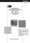
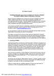
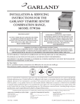
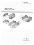
Precision Cooling
For Business-Critical Continuity
Liebert XDWP™
User Manual - 100kW Nominal Capacity, 50 & 60 Hz
GENERAL SAFETY GUIDELINES
!
CAUTION
!
WARNING
This system contains hazardous electrical voltage. Disconnect all power before working
within.
Before proceeding with installation of XDWP, read all instructions, verify that all the parts
are included, and check the nameplate to be sure the XDWP voltage matches available utility
power.
Follow all local codes.
The XDWP is top-heavy. Use extreme caution and care when moving and installing this unit.
NOTE
This document shall be used together with site specific documentation and documentation for
other parts of the system.
NOTE
Before any action that could cause a disturbance in the XD system’s cooling function is begun,
the facility manager MUST be informed. In addition, after the action is taken and the work is
finished, the facility manager MUST be informed.
Figure i
Model number nomenclature
Example: CDU100C-A000
CDU
100
C
= 100kW nominal
capacity
–
A
Placeholder
0
0
0
0 = Basic unit
= Coolant Distribution Unit
0 = Revision
level
C = Chilled water
A = 460V-3ph-60Hz
C = 208V-3ph-60Hz
M = 380/415V-3ph-50Hz
Placeholder
TABLE OF CONTENTS
GENERAL SAFETY GUIDELINES . . . . . . . . . . . . . . . . . . . . . . . . . . . . . . . . . . . INSIDE FRONT COVER
1.0
PRODUCT DESCRIPTION . . . . . . . . . . . . . . . . . . . . . . . . . . . . . . . . . . . . . . . . . . . . . . . . . . .1
1.1
General Product Information. . . . . . . . . . . . . . . . . . . . . . . . . . . . . . . . . . . . . . . . . . . . . . . . . . . 1
1.1.1
Product/System Description. . . . . . . . . . . . . . . . . . . . . . . . . . . . . . . . . . . . . . . . . . . . . . . . . . . . . 1
1.2
Checking and Unpacking . . . . . . . . . . . . . . . . . . . . . . . . . . . . . . . . . . . . . . . . . . . . . . . . . . . . . . 1
1.3
Equipment Inspection . . . . . . . . . . . . . . . . . . . . . . . . . . . . . . . . . . . . . . . . . . . . . . . . . . . . . . . . 1
1.4
Equipment Handling . . . . . . . . . . . . . . . . . . . . . . . . . . . . . . . . . . . . . . . . . . . . . . . . . . . . . . . . . 2
1.5
1.4.1
Handling With Skid . . . . . . . . . . . . . . . . . . . . . . . . . . . . . . . . . . . . . . . . . . . . . . . . . . . . . . . . . . . 2
1.4.2
Removal from Skid . . . . . . . . . . . . . . . . . . . . . . . . . . . . . . . . . . . . . . . . . . . . . . . . . . . . . . . . . . . . 2
1.4.3
Removing Piano Jacks . . . . . . . . . . . . . . . . . . . . . . . . . . . . . . . . . . . . . . . . . . . . . . . . . . . . . . . . . 4
Mechanical Considerations . . . . . . . . . . . . . . . . . . . . . . . . . . . . . . . . . . . . . . . . . . . . . . . . . . . . 5
1.5.1
1.6
Positioning the XDWP . . . . . . . . . . . . . . . . . . . . . . . . . . . . . . . . . . . . . . . . . . . . . . . . . . . . . . . . . 5
High Voltage Connections . . . . . . . . . . . . . . . . . . . . . . . . . . . . . . . . . . . . . . . . . . . . . . . . . . . . . 6
1.6.1
Connecting High-Voltage Cables . . . . . . . . . . . . . . . . . . . . . . . . . . . . . . . . . . . . . . . . . . . . . . . . . 6
1.7
Extra Low Voltage (ELV) Connections . . . . . . . . . . . . . . . . . . . . . . . . . . . . . . . . . . . . . . . . . . 10
2.0
PIPING . . . . . . . . . . . . . . . . . . . . . . . . . . . . . . . . . . . . . . . . . . . . . . . . . . . . . . . . . . . . . . .12
2.1
Connection Sizes. . . . . . . . . . . . . . . . . . . . . . . . . . . . . . . . . . . . . . . . . . . . . . . . . . . . . . . . . . . . 12
2.1.1
Recommended Pipe Size. . . . . . . . . . . . . . . . . . . . . . . . . . . . . . . . . . . . . . . . . . . . . . . . . . . . . . . 12
2.2
Air Bleeders . . . . . . . . . . . . . . . . . . . . . . . . . . . . . . . . . . . . . . . . . . . . . . . . . . . . . . . . . . . . . . . 12
2.3
Insulation . . . . . . . . . . . . . . . . . . . . . . . . . . . . . . . . . . . . . . . . . . . . . . . . . . . . . . . . . . . . . . . . . 12
2.4
System Schematic. . . . . . . . . . . . . . . . . . . . . . . . . . . . . . . . . . . . . . . . . . . . . . . . . . . . . . . . . . . 12
2.5
Piping Details—Shutoff/Isolation Valves . . . . . . . . . . . . . . . . . . . . . . . . . . . . . . . . . . . . . . . . 13
2.6
Bypass Flow Controllers . . . . . . . . . . . . . . . . . . . . . . . . . . . . . . . . . . . . . . . . . . . . . . . . . . . . . 13
2.7
Filling Instructions. . . . . . . . . . . . . . . . . . . . . . . . . . . . . . . . . . . . . . . . . . . . . . . . . . . . . . . . . . 14
2.7.1
Check for Proper Installation of Components and Workmanship . . . . . . . . . . . . . . . . . . . . . . 14
2.7.2
Conduct Air Pressure Test . . . . . . . . . . . . . . . . . . . . . . . . . . . . . . . . . . . . . . . . . . . . . . . . . . . . . 14
2.7.3
Water Fill Line Connection . . . . . . . . . . . . . . . . . . . . . . . . . . . . . . . . . . . . . . . . . . . . . . . . . . . . 14
2.8
Checklist for Proper Installation . . . . . . . . . . . . . . . . . . . . . . . . . . . . . . . . . . . . . . . . . . . . . . . 15
3.0
OPERATION . . . . . . . . . . . . . . . . . . . . . . . . . . . . . . . . . . . . . . . . . . . . . . . . . . . . . . . . . . .16
3.1
Feature Overview . . . . . . . . . . . . . . . . . . . . . . . . . . . . . . . . . . . . . . . . . . . . . . . . . . . . . . . . . . . 16
3.1.1
Display . . . . . . . . . . . . . . . . . . . . . . . . . . . . . . . . . . . . . . . . . . . . . . . . . . . . . . . . . . . . . . . . . . . . 16
i
3.2
Main Menu - MENU Key . . . . . . . . . . . . . . . . . . . . . . . . . . . . . . . . . . . . . . . . . . . . . . . . . . . . . 17
3.2.1
Viewing or Changing Settings . . . . . . . . . . . . . . . . . . . . . . . . . . . . . . . . . . . . . . . . . . . . . . . . . . 17
3.2.2
SETPOINTS . . . . . . . . . . . . . . . . . . . . . . . . . . . . . . . . . . . . . . . . . . . . . . . . . . . . . . . . . . . . . . . . 17
3.2.3
STATUS . . . . . . . . . . . . . . . . . . . . . . . . . . . . . . . . . . . . . . . . . . . . . . . . . . . . . . . . . . . . . . . . . . . 17
3.2.4
ACTIVE ALARMS . . . . . . . . . . . . . . . . . . . . . . . . . . . . . . . . . . . . . . . . . . . . . . . . . . . . . . . . . . . 18
3.2.5
ALARM HISTORY . . . . . . . . . . . . . . . . . . . . . . . . . . . . . . . . . . . . . . . . . . . . . . . . . . . . . . . . . . . 18
3.2.6
TIME . . . . . . . . . . . . . . . . . . . . . . . . . . . . . . . . . . . . . . . . . . . . . . . . . . . . . . . . . . . . . . . . . . . . . . 18
3.2.7
DATE. . . . . . . . . . . . . . . . . . . . . . . . . . . . . . . . . . . . . . . . . . . . . . . . . . . . . . . . . . . . . . . . . . . . . . 18
3.2.8
SETUP OPERATION . . . . . . . . . . . . . . . . . . . . . . . . . . . . . . . . . . . . . . . . . . . . . . . . . . . . . . . . . 18
3.2.9
Password Security—SETPT PASSWORD and SERVICE PASSWORD . . . . . . . . . . . . . . . . . 20
3.2.10 CALIBRATE SENSOR . . . . . . . . . . . . . . . . . . . . . . . . . . . . . . . . . . . . . . . . . . . . . . . . . . . . . . . . 21
3.2.11 ALARM ENABLE. . . . . . . . . . . . . . . . . . . . . . . . . . . . . . . . . . . . . . . . . . . . . . . . . . . . . . . . . . . . 21
3.2.12 ALARM TIME DELAY. . . . . . . . . . . . . . . . . . . . . . . . . . . . . . . . . . . . . . . . . . . . . . . . . . . . . . . . 21
3.2.13 COMMON ALARM ENABLE . . . . . . . . . . . . . . . . . . . . . . . . . . . . . . . . . . . . . . . . . . . . . . . . . . 21
3.2.14 CUSTOM ALARMS . . . . . . . . . . . . . . . . . . . . . . . . . . . . . . . . . . . . . . . . . . . . . . . . . . . . . . . . . . 21
3.2.15 CUSTOM TEXT . . . . . . . . . . . . . . . . . . . . . . . . . . . . . . . . . . . . . . . . . . . . . . . . . . . . . . . . . . . . . 21
3.2.16 DIAGNOSTICS. . . . . . . . . . . . . . . . . . . . . . . . . . . . . . . . . . . . . . . . . . . . . . . . . . . . . . . . . . . . . . 22
4.0
ALARM DESCRIPTIONS AND SOLUTIONS . . . . . . . . . . . . . . . . . . . . . . . . . . . . . . . . . . . . . .23
4.1
Alarm Descriptions. . . . . . . . . . . . . . . . . . . . . . . . . . . . . . . . . . . . . . . . . . . . . . . . . . . . . . . . . . 23
4.2
Red and Green Lamp Indicators . . . . . . . . . . . . . . . . . . . . . . . . . . . . . . . . . . . . . . . . . . . . . . . 23
4.3
Alter Alarm Settings . . . . . . . . . . . . . . . . . . . . . . . . . . . . . . . . . . . . . . . . . . . . . . . . . . . . . . . . 24
4.3.1
Enable or Disable Alarms . . . . . . . . . . . . . . . . . . . . . . . . . . . . . . . . . . . . . . . . . . . . . . . . . . . . . 24
4.3.2
Increase or Decrease Alarm Time Delays . . . . . . . . . . . . . . . . . . . . . . . . . . . . . . . . . . . . . . . . . 24
4.4
System Shutdown Causes . . . . . . . . . . . . . . . . . . . . . . . . . . . . . . . . . . . . . . . . . . . . . . . . . . . . 25
5.0
SPECIFICATIONS . . . . . . . . . . . . . . . . . . . . . . . . . . . . . . . . . . . . . . . . . . . . . . . . . . . . . . . .26
ii
FIGURES
Figure i
Figure 1
Figure 2
Figure 3
Figure 4
Figure 5
Figure 6
Figure 7
Figure 8
Figure 9
Figure 10
Figure 11
Figure 12
Figure 13
Figure 14
Figure 15
Figure 16
Figure 17
Figure 18
Figure 19
Model number nomenclature . . . . . . . . . . . . . . . . . . . . . . . . . . . . . . . . . . . . . . . . . Inside Front Cover
Generic system schematic . . . . . . . . . . . . . . . . . . . . . . . . . . . . . . . . . . . . . . . . . . . . . . . . . . . . . . . . . 1
Tie-down brackets and lag bolts to be removed. . . . . . . . . . . . . . . . . . . . . . . . . . . . . . . . . . . . . . . . . 2
Removing pallet boards for piano jack insertion . . . . . . . . . . . . . . . . . . . . . . . . . . . . . . . . . . . . . . . . 3
XDWP strapped to piano jack. . . . . . . . . . . . . . . . . . . . . . . . . . . . . . . . . . . . . . . . . . . . . . . . . . . . . . . 3
Remove remaining lag bolts from one runner . . . . . . . . . . . . . . . . . . . . . . . . . . . . . . . . . . . . . . . . . . 3
Remove runner from pallet. . . . . . . . . . . . . . . . . . . . . . . . . . . . . . . . . . . . . . . . . . . . . . . . . . . . . . . . . 4
Sliding pallet from under XDWP . . . . . . . . . . . . . . . . . . . . . . . . . . . . . . . . . . . . . . . . . . . . . . . . . . . . 4
Dimensions, access points and external features . . . . . . . . . . . . . . . . . . . . . . . . . . . . . . . . . . . . . . . 5
Front view of XDWP and electrical enclosure . . . . . . . . . . . . . . . . . . . . . . . . . . . . . . . . . . . . . . . . . . 6
Electrical enclosure knockout locations for field wiring . . . . . . . . . . . . . . . . . . . . . . . . . . . . . . . . . . 7
High voltage connections - 60Hz . . . . . . . . . . . . . . . . . . . . . . . . . . . . . . . . . . . . . . . . . . . . . . . . . . . . 8
High voltage connections - 50Hz . . . . . . . . . . . . . . . . . . . . . . . . . . . . . . . . . . . . . . . . . . . . . . . . . . . . 9
Electrical enclosure knockout locations for ELV. . . . . . . . . . . . . . . . . . . . . . . . . . . . . . . . . . . . . . . 10
XDWP ELV field connection points . . . . . . . . . . . . . . . . . . . . . . . . . . . . . . . . . . . . . . . . . . . . . . . . . 11
Piping details. . . . . . . . . . . . . . . . . . . . . . . . . . . . . . . . . . . . . . . . . . . . . . . . . . . . . . . . . . . . . . . . . . . 13
XDWP filling components. . . . . . . . . . . . . . . . . . . . . . . . . . . . . . . . . . . . . . . . . . . . . . . . . . . . . . . . . 14
Standpipe filling components . . . . . . . . . . . . . . . . . . . . . . . . . . . . . . . . . . . . . . . . . . . . . . . . . . . . . . 14
Detailed view of XDWRs (top) . . . . . . . . . . . . . . . . . . . . . . . . . . . . . . . . . . . . . . . . . . . . . . . . . . . . . 15
User interface . . . . . . . . . . . . . . . . . . . . . . . . . . . . . . . . . . . . . . . . . . . . . . . . . . . . . . . . . . . . . . . . . . 16
TABLES
Table 1
Table 2
Table 3
Table 4
Table 5
Table 6
Table 7
Supply and return requirements for XDWR loop . . . . . . . . . . . . . . . . . . . . . . . . . . . . . . . . . . . . . .
Fixed-flow bypass controller requirements . . . . . . . . . . . . . . . . . . . . . . . . . . . . . . . . . . . . . . . . . . .
User interface keypad functions. . . . . . . . . . . . . . . . . . . . . . . . . . . . . . . . . . . . . . . . . . . . . . . . . . . .
Setpoint functions, default values and allowable ranges . . . . . . . . . . . . . . . . . . . . . . . . . . . . . . . .
Setup functions, default values and allowable ranges . . . . . . . . . . . . . . . . . . . . . . . . . . . . . . . . . .
XDWP DIP switches and factory settings . . . . . . . . . . . . . . . . . . . . . . . . . . . . . . . . . . . . . . . . . . . .
Liebert XDWP specifications . . . . . . . . . . . . . . . . . . . . . . . . . . . . . . . . . . . . . . . . . . . . . . . . . . . . . .
iii
12
13
16
17
18
19
26
iv
Product Description
1.0
PRODUCT DESCRIPTION
1.1
General Product Information
1.1.1
Product/System Description
The Liebert XDWP is an interface between the building chilled water system and the XDWR coolant
circuit. It is designed to circulate and control coolant to XDWRs that are installed on racks with heat
dissipating equipment. The unit consists of a cabinet that includes a heat exchanger, two circulating
pumps (for redundancy), a flow switch, a control valve, an expansion tank, controls, valves and piping. See Figure 1.
The control in the XDWP monitors room conditions and controls the leaving fluid temperature to
XDWR to always be above the room dew point, to prevent coil condensation.
All functions, such as switching pumps and fluid temperature control, are automatic.
The XDWP is rated for 100 kW (341,300 BTU/h) of cooling.
Figure 1
Generic system schematic
Liebert XDWP
Control
valve
Expansion
tank
Pumps
XDWR fan
coils
Chilled water
Heat
exchanger
1.2
Checking and Unpacking
Check the received materials to be sure all required assemblies and parts have been received. If you
discover any external damages, report them to the shipping company. If you later find any concealed
damages, report it to the shipping company and your local Liebert representative.
NOTE
The XDWP should always remain in a vertical position.
1.3
Equipment Inspection
When the unit is delivered, inspect all items for visible and concealed damage. Damage should be
immediately reported to the carrier and a damage claim filed with a copy sent to Liebert or to your
sales representative.
1
Product Description
1.4
1.4.1
Equipment Handling
!
WARNING
!
CAUTION
The instructions listed below are to be followed when handling this unit with or without the
skid. This unit has the potential to tip over if handled improperly, which would damage the
unit and could injure or kill personnel.
Personnel should be properly trained and certified to move and rig equipment.
Handling With Skid
• Always keep the unit upright, indoors and protected from damage.
• If possible, transport the unit using a forklift truck. Otherwise use a crane with belts or cables. In
either case, do NOT press on the top edges of the packaging.
• If using a forklift, make sure the forks (if adjustable) are spread to the widest allowable distance
to still fit under the skid.
• When moving the skidded unit with a forklift truck, do not lift the unit any higher than 6"
(152mm) off the ground. If circumstances require the unit to be lifted higher than 6" (152mm),
great care must be exercised and all by-standing personnel are to be no closer than 20' (5m) from
the lift point of the unit.
!
1.4.2
CAUTION
Attempting to move the XDWP while it is still on the skid through a standard doorway will
damage the unit. The XDWP on the skid will not fit through a standard doorway, which
measures 83" (2108mm) tall.
Removal from Skid
Liebert recommends using dual hand trucks or a similar method to remove the XDWP from the skid.
This is to ensure that both ends of the unit are firmly secure and to provide a good means of unit
mobility.
1. Always keep the unit upright, indoors, and protected from possible damage.
2. Remove the exterior packaging. Leave the plastic bag over the XDWP until the unit has been
moved to its final location. The bag will protect the painted panels against scuffing.
3. Remove two (2) corner tie-down brackets from one side of the unit, on a non-runner notch side of
the pallet. Remove eight (8) lag bolts from two (2) end deck boards on the same end where the
tie-down brackets were removed (refer to Figure 2).
Figure 2
Tie-down brackets and lag bolts to be removed
Remove these 4 lag bolts
to free deck boards
Remove these 2
tie-down brackets
Remove these 4 lag bolts
to free deck boards
2
Product Description
4. Remove the two (2) end deck boards from one end of the pallet and the attached, notched section
of the center runners (refer to Figure 3).
Figure 3
Removing pallet boards for piano jack insertion
Remove two deck boards ...
... and center runner sections
from one end of pallet.
5. Place a piano jack with its forks snugly against the bottom of the unit and strap the XDWP
securely to the jack (refer to Figure 4).
NOTE
Place a mover’s blanket or other cushioning material between the jack and the unit’s side
panels.
Figure 4
XDWP strapped to piano jack
Piano jack
Strap secures
XDWP to jack
Place cushioning material
between the forks and the XDWP
to protect XDWP’s finish
(cushion not shown for clarity)
Piano jack’s forks should
be snug against the XDWP
6. Repeat Steps 2, 4 and 5 for the opposite side of the unit. When these steps have been completed,
the XDWP will be supported by two piano jacks, one on either side.
7. Remove all of the remaining lag bolts from one (1) of the pallet’s outside runners (see Figure 5).
Figure 5
Remove remaining lag bolts from one runner
Remaining 6 lag bolts
to remove
3
Product Description
8. Remove the runner from which all lag bolts have been removed (refer to Figure 6).
Figure 6
Remove runner from pallet
Slide this runner
away from XDWP
9. Using the pallet jacks, raise the secured unit to the highest point that the piano jacks will allow.
Once the unit has been raised, slide the remainder of the pallet from under the XDWP (see
Figure 7). Lower the XDWP so that its base is approximately 1" (25.4mm) off the ground.
Figure 7
Sliding pallet from under XDWP
Slide remaining part of pallet from
under XDWP so the unit may be
moved on the piano jacks.
1.4.3
Removing Piano Jacks
Once the unit has been moved to the installation location, Liebert recommends the following method
to remove the piano jacks:
1.
2.
3.
4.
Lower the unit as far as the piano jacks will allow.
Undo all strapping holding the piano jacks to the unit.
Remove all cushioning material used to protect the unit from the straps and the piano jacks.
Use a pry bar or other lever to lift one side of the XDWP enough to allow removal of the piano
jack.
5. Repeat Step 4 to remove the piano jack on the opposite side.
6. Remove the plastic bag.
4
Product Description
1.5
Mechanical Considerations
1.5.1
Positioning the XDWP
Install the XDWP according to the site-specific documentation and secure the unit to the floor.
The XDWP may be installed close to a wall or another XDWP. To provide access to all components in
the unit, however, the front of the unit must have at least 3 ft. (0.9m) free service area.
Figure 8
Dimensions, access points and external features
15-7/16"
(392mm)
11-7/16"
(291mm)
Water Return (In) From
XDWR - 2-1/8" O.D.
Water Supply (Out)
To XDWR - 2-1/8" O.D.
7-7/8" (200mm)
5-3/16" (132mm)
3-3/16" (81mm)
9-9/16" (243mm)
To Temperature/Humidity
Wiring (Field-Installed)
34"
(864mm)
To User Interface
Wiring (Field-Installed)
Supply (In) From
Building Chilled
Water - 2-1/8" O.D.
Fill Water Source
Connection, 5/8”O.D.
Return (Out) To
Building Chilled
Water - 2-1/8" O.D.
3-Phase
Power
Source
Conduit connections
38"
(965mm)
20"
(508mm)
Door Access
36"
(914mm)
Service Access
36"
(914mm)
Service Access
38"
(965mm)
Disconnect
Switch
Status
Lamps
User
Interface
78"
(1981mm)
5
17"
(432mm)
17"
(432mm)
18"
(457mm)
Installation Access
Product Description
1.6
High Voltage Connections
Make sure the actual supply voltage and frequency correspond to the voltage and frequency indicated
on the XDWP’s rating plate.
Connect cables for high voltage supply to the electrical box in the XDWP according to Figure 11 and
make sure that the phases are correctly connected.
The unit must be installed in accordance with national wiring regulations.
1.6.1
!
WARNING
!
CAUTION
Risk of electric shock. Can cause injury or death.
Disconnect all local and remote electric power before working within the unit.
Sharp edges and heavy parts may cause personal injury.
Wear gloves to prevent injury to hands.
Damage to wiring or components may make unit unsafe to operate.
Use caution when installing wiring to prevent damage to factory wiring.
Install protective bushings in wiring knockouts as required
Do not disturb factory wiring or route field-installed wiring over electrical terminals.
Use NEC Class 1 wiring for all hazardous voltage electrical power supplies.
Check and retighten all wiring connections before starting.
Connecting High-Voltage Cables
1. Turn the XDWP’s disconnect switch to the Off position (see Figure 9). Open the front doors and
push down on the enclosure cover latch to open the hazardous voltage enclosure cover.
Figure 9
Front view of XDWP and electrical enclosure
Status Lamps
User Interface
Disconnect
Switch
Enclosure Cover Latch
Hazardous Voltage
Enclosure Cover
FRONT VIEW
ELECTRICAL ENCLOSURE
6
Product Description
2. Determine which knockouts in the electrical enclosure will be used and remove them (see
Figure 10).
Figure 10 Electrical enclosure knockout locations for field wiring
High Voltage Connections (60Hz)
XDWP Input
Power Knockout
Enclosure Cover Not Shown for Clarity
3. Route the input hazardous voltage electrical power wiring through the top left knockout (see
Figure 10) to the disconnect switch L1, L2 and L3 (see Figures 11 and 12). Observe proper
phasing.
4. Connect the ground wire to the ground lug (see Figures 11 and 12), which is in the middle left of
the enclosure.
7
Product Description
Figure 11
High voltage connections - 60Hz
High Voltage Connections (60Hz)
Field High Voltage Connection
Power Block
Transformer 2
Ground
Lug
Disconnect
Switch
Fuse Block
Transformer 1
Fuse Block
Contactor
8
Product Description
Figure 12 High voltage connections - 50Hz
Field High Voltage Connection
Power Block
Transformer 2
Ground
Lug
Disconnect
Switch
Fuse Block
Circuit
Breaker
Contactor
Transformer 1
Fuse Block
9
Product Description
1.7
Extra Low Voltage (ELV) Connections
ELV power output is 30V and 100VA or less.
1. Turn off all unit power before connecting cables or wires. Failure to do so may damage this
equipment (refer to Figure 13).
2. Route low voltage electrical connections through the appropriate knockouts as indicated below.
3. User interface requires four thermostat-type wires (jacketed) connected to the control board (see
Figure 14).
Figure 13 Electrical enclosure knockout locations for ELV
High Voltage Connections (50Hz)
XDWP Input
Power Knockout
10
Product Description
Field Connections—All Units
• Connect the control display panel cable to terminal block TB3 terminals 1 through 4 on the
XDWP control board as shown (refer to Figure 14). The display panel may be mounted in the
XDWP front right door if the XDWP is located in the area that it conditions. The display panel
must always be installed in the conditioned space.
• Connect the provided remote temperature / humidity sensor extension cable to the factoryinstalled cable connected to P16 on the control board. Install this sensor in the higher-temperature portion of the cold aisle in the space conditioned by the XDWR units connected to the XDWP.
• Place the sensor on the RETURN AIR side of the primary air mover (e.g., Liebert Deluxe
System 3) or directly in the cool aisle. Do not install the sensor where ambient air may cause false
readings, for example, near unsealed doors, windows and similar areas.
Figure 14 XDWP ELV field connection points
Extra Low Voltage (ELV) Connections
Control Display Panel
Cable Provided With
Display Panel TB3
Temperature/Humidity Sensor
Cable Provided With Temperature
Humidity Sensor Board
REMOTE ALARM DEVICE
FOR INDICATION OF ALARM, WIRE
N.O. CONTACTS FROM REMOTE
ALARM DEVICE AS SHOWN
1
24
50
N.O. CONTACT BY OTHERS
H2O (24)
RAD1 (50)
1
K3COM
K3NO
K3NCL
38
37
COMMON ALARM OUTPUT
FOR CONTACTS INDICATING AN
ALARM CONDITION.
K3
K3NO
K3
K3COM
K3NC
TO REMOTE ALARM
CIRCUIT BY OTHERS
REMOTE SHUTDOWN
FOR SHUTDOWN OF CONTROL
CIRCUIT, REMOVE JUMPER
BETWEEN TERMINALS 37 & 38
AND REPLACE WITH N.C. CONTACT
37
38
N.C. CONTACTS BY OTHERS
1
77
78
LIEBERT SITE MONITOR
FOR DIGITAL COMMUNICATIONS
WITH LIEBERT SITE MONITORS
ONLY. CONNECT 2 WIRE TWISTED
PAIR TO 77 & 78. ALSO SEE SITE
MONITOR INSTALLATION MANUAL..
77
(-)
BK
NOTES:
1
Control wiring must be installed in accordance
with the National Electrical Code (NEC) Class 2 Circuit.
11
78
(+)
R or W
Piping
2.0
PIPING
2.1
Connection Sizes
The copper pipe connections on the XDWP are as follows.
Building Chilled Water Supply
2-1/8" OD
Chilled Water Return
2-1/8" OD
Coolant Supply
2-1/8" OD
Coolant Return
2-1/8" OD
Fill Water Source
2.1.1
5/8" OD
Recommended Pipe Size
Connect the main pipes between the XDWP and the XDWR according to site-specific documentation
and the configuration guide for the XDWR unit.
Elbows and restrictions should be minimized to get good fluid flow.
Table 1
2.2
Supply and return requirements for XDWR loop
Nominal Pipe Size
inches (mm)
Maximum Total
Equivalent Length
ft. (m)
Piping Material
2.5 (64)
75 (23)
Type L Copper
3 (76)
150 (46)
Copper or Sch 40 Steel
3.5 (89)
300 (91)
Copper or Sch 40 Steel
Air Bleeders
Install air bleeders at each high point in the piping circuits.
2.3
Insulation
To avoid the risk of condensation, all piping between the XDWP and the XDWR that are not in a conditioned space shall be insulated.
2.4
System Schematic
For complete system schematic for a system with the XDWP, see site-specific documentation and
manuals for the XDWR.
12
Piping
2.5
Piping Details—Shutoff/Isolation Valves
To allow for maintenance of the XDWP, isolation valves are installed on the supply and return pipes
for both the chilled water circuit and the coolant circuit connected to the XDWP (see Figure 15).
Figure 15 Piping details
Building CW Return
Building CW Supply
Isolation
Valves
Floor
NOTE
If the chilled water supply is an open loop system, Liebert strongly recommends installing a
20-40 mesh strainer on the supply line of the XDWP to prevent particles and contaminants
from entering the heat exchanger.
2.6
Bypass Flow Controllers
The XDWP is designed for a nominal cooling module side circuit flow of 75 gpm (284 lpm). However,
to ensure optimal functionality, the flow should be kept above 18 gpm (68 lpm).
If fewer than three XDWR modules are connected to the XDWP circuit, fixed-flow bypass controllers
must be installed between the supply and return piping in parallel with the modules (see Table 2).
Each fixed-flow bypass controller has a nominal flow of 6 gpm (23 lpm).
If the XDWP is circulating cold water to other devices—for example, some models of IBM’s Rear Door
Heat eXchanger—installing minimum-flow bypass controllers in a similar way may be required to
keep the flow in the circuit above 18 gpm (68 lpm). These minimum-flow bypass controllers must be
installed between the supply and return piping in parallel with the modules.
The bypass flow controller is soldered between the supply and return distribution piping that connects the XDWP with the cooling modules. The bypass may be installed wherever convenient in the
distribution piping, but it should be placed so that air is not trapped inside. The fixed-flow bypass controller must be protected from excessive heat during installation. Do not use hard solder. Soft solder
is recommended. For convenience, the fixed-flow bypasses may be installed with optional shutoff
valves to deactivate the bypass flow controllers when more modules are added.
Table 2
Fixed-flow bypass controller requirements
Number of XDWR Units
on XDWP Circuit
Number of Fixed-Flow Bypass Controllers Required
P/N 184181G1 (Nominal Flow 6 gpm [23 lpm])
1
2
2
1
3-12
0
13
Piping
2.7
Filling Instructions
This section provides detailed instructions on how to properly fill the XDWP.
2.7.1
Check for Proper Installation of Components and Workmanship
1. Confirm that the flow directions of
field-installed components are correct.
2. Confirm that all isolating valves are
open (keep the hose bib valve closed
when filling).
3. Confirm that all auto air vents are
closed (tighten caps if applicable).
4. Test the water quality when filling the
system. Refer to these desired
parameters for minimum corrosion and
erosion:
2.7.2
Conductivity
Maximum = 500µS/cm
PH-value
Minimum = 7.0
Suspended
matter
No visible particles
Maximum = 30 mg/L
Taste and smell
Normal
g
Standpipe
Sightglass
Pump1
Housing
Plug
Sightglass
"Fill" Line
Pump2
Housing
Plug
Valve #2
Hose Bib
Valve #1
FRONT
CDU
FRONT
OF OF
XDWP
Conduct Air Pressure Test
1. Turn Off power to the unit.
2. Set the pressure at 150 psig (1034kPa; 10.3 bars) maximum for at
least 30 minutes or according to local codes.
3. Repair any leaks if necessary.
2.7.3
p
Filling components
Figure 16 XDWP filling
Figure 17 Standpipe
filling
components
Water Fill Line Connection
!
CAUTION
Check with local codes for proper connection to potable water
and EPA conformance.
Do NOT use the hose bib at the bottom of the unit to fill the
system (see Figures 16 and 17).
Fill line on
sightglass
1. When filling the system, use only water that can be classified and
used as drinking water.
a. Open all vents (loosen caps if applicable) to allow air to escape
during filling.
Hose
bib
b. Remove the Schrader pin in the valve at the top of the
standpipe (see Figure 17) to obtain 0 psig pressure.
c. Open Valve #1 and #2 to allow the system to fill (see
FRONT OF XDWP (ANGLED)
Figure 16).
d. When the water has reached the FILL line in the sightglass tube of the standpipe,
immediately close Valve #1 (see Figure 16) to isolate the standpipe from the system.
e. Replace the Schrader pin in the valve at the top of the standpipe.
2. Bleed air thoroughly (keep Valve #1 closed to isolate the standpipe from the system).
a. Depress pins at all vents.
b. Manually depress pins at all Schrader vents on each rack (see Figure 18).
c. Manually vent at pump housing plugs (see Figure 16).
d. Continue to vent until the system is full, then close Valve #2.
14
Piping
3. Open Valve #1 to reconnect the system to the
Figure 6C view
Detailed
View of Rackcoolers
(To
Figure 18 Detailed
of XDWRs
(top)
standpipe (fluid level in the clear tube should
rise above the fill, but below NORMAL level).
a. If the fluid level is above the NORMAL line,
release water by opening the hose bib until
the level reaches the NORMAL line.
schrader vents
b. If the fluid level is below the NORMAL line,
open Valve #2 until the level reaches the
NORMAL line.
4. Turn the system on (pumps will be in operation)
and continue to vent air for 24 hours to remove
as much air as possible.
Note: Add water as necessary to maintain a
normal level reading on the clear tube.
5. When the system is mostly air-free, close ALL
air vents (tighten caps securely); this includes vents at each rack (Figure 18) and auto air vents
on the main headers.
6. Conduct a Fluid Pressure Test.
a. Shut off the ball valve on the standpipe pressure gauge to avoid overpressurization (see
Figure 17).
b. Pressure test the system with water at city pressure for six hours or according to local codes.
c. Check for leaks.
7. Add a water corrosion inhibitor.
• The use of a closed system treatment (CST) is strongly recommended. CST is available from
TERLYN INDUSTRIES at 800-200-4112 or www.terlyn.com.
• Additional treatment might be required after six to 12 months of operation, depending on the
quality of your water.
Note: Many parameters contribute to water corrosion and erosion, and the requirements stated
above do not guarantee 100% corrosion and erosion prevention. However, when these parameters
are met and a corrosion inhibitor is used, the possibility of corrosion and erosion in the closed loop
water system should be minimized, therefore maximizing the life expectancy of the system.
8. Refill the system by following Steps 1 through 5, then go to Step 9.
9. Turn the unit On by pressing the I/O key.
2.8
Checklist for Proper Installation
___ 1. Unpack and check received material.
___ 2. Position the XDWP and secure to the floor.
___ 3. Wire high-voltage connections.
___ 4. Wire low-voltage connections.
___ 5. Connect building chilled water piping to the XDWP.
___ 6. Connect XDWR piping to the XDWP.
___ 7. Make sure air vents are installed at high-point of the system.
___ 8. Make sure isolation valves are installed on the mains and branch piping.
___ 9. Pressure test air.
___ 10. Fill the system with water.
___ 11. Bleed air out of the system.
___ 12. Pressure test fluid.
15
Operation
3.0
OPERATION
3.1
Feature Overview
The XDWP controls the coolant temperature to a XDWR system above the room dewpoint, preventing
coil condensation.
The microprocessor control for the Liebert XDWP unit features an easy-to-use menu-driven LCD. The
menus, control features and circuit board details are described in this section.
Figure 19 User interface
Up Arrow Key
Status Display
Down Arrow Key
On/Off Key
Alarm Silence Key
Active alarms are displayed on the LCD screen and sound an audible beep. To silence an alarm, press
the Alarm Silence/Help key as prompted on the display.
Setpoints, DIP switch settings and other selections were made during factory testing of the unit based
on typical operating experience. (Other default selections were made according to options included
with the unit.)
ADJUST THE FACTORY DEFAULTS ONLY IF THEY DO NOT MEET YOUR SPECIFICATIONS.
Allowable ranges are displayed by pressing the Help key. A password will be required (if enabled) to
change setpoints, time delays, etc.
The display normally shows the leaving coolant temperature on the first line and alternates between
the dew point and the number of alarms present on the second line.
3.1.1
Display
To turn the unit On, press the On/Off (I/O) key after power is applied to the XDWP.
To turn the unit Off, press the On/Off (I/O) key before power is disconnected.
Table 3
User interface keypad functions
Keypad
Function
On/Off (I/O)
Turns the unit On or Off (top far left keypad)
Menu
Enables the user to access the program menu to change setpoints, alarms, etc. (top near left)
Up Arrow Key
Raises the value of displayed parameter while in a set mode (setpoints, time, etc.) (arrow, top
near right)
Escape (Esc)
Allows user to move back to a previous menu (top far right)
Alarm Silence
If an alarm is present, press this key to silence the alarm. Help text will appear if this key is
pressed when no alarm is present (bottom left)
Down Arrow
Key
Lowers the value of displayed parameter while in a set mode (set points, time, etc.) (arrow,
bottom near right).
Enter
After setting a control value, press ENTER to store the information in the microprocessor
(bottom right).
16
Operation
3.2
Main Menu - MENU Key
Press the MENU key to display the Main Menu. The menu selections are:
•
•
•
•
•
•
•
•
•
•
•
•
•
•
•
•
•
3.2.1
SETPOINTS
STATUS
ACTIVE ALARMS
ALARM HISTORY
TIME
DATE
SETUP OPERATION
SETPT PASSWORD
SERVICE PASSWORD
CALIBRATE SENSOR
ALARM ENABLE
ALARM TIME DELAY
COMMON ALARM ENABLE
CUSTOM ALARMS
CUSTOM TEXT
DIAGNOSTICS
END OF MENU
Viewing or Changing Settings
To access a menu option:
1.
2.
3.
4.
3.2.2
Use the up or down arrow key to scroll to the menu option.
Press the ENTER key to view the current setting.
To change the setting, use the up or down arrow key.
Press ENTER to save the change.
SETPOINTS
Selecting SETPOINTS from the Main Menu will display the following menu items:
• MIN TEMP SP
• HI FLD TEMP
Scroll through this submenu by using the up or down arrow key. Press ENTER to select a particular
function. To change a particular value, press ENTER, then use the up and down arrow keys to change
the value. When the value has been changed press ENTER to store the value.
For example, to change the MIN TEMP SP:
a.
b.
c.
d.
e.
f.
g.
From the main status display, press MENU.
Scroll to the SETPOINTS using the up or down arrow key.
Press ENTER to select the SETPOINTS submenu.
Scroll to MIN TEMP SP using the up or down arrow key.
Press ENTER.
Use the up arrow key to increase the value or the down arrow key to lower the value.
Press ENTER to store.
Table 4 shows the default values and allowable ranges for these setpoints.
Table 4
Setpoint functions, default values and allowable ranges
Menu Item
MIN TEMP SP
HI FLD TEMP
3.2.3
Function
Minimum Room Temperature Setpoint
High Fluid Temperature Setpoint
Default
60°F (16°C)
80°F (27°C)
Range
40 to 80°F (4 to 27°C)
30 - 95°F (-1 to 35°C)
STATUS
The user can check the status of the control valve, from 0-100% open, the operating status of the two
(2) pumps, and the fluid temperature.
17
Operation
3.2.4
ACTIVE ALARMS
This submenu allows the user to review what alarms, if any, are present. The screen will read either
“No Alarms Present,” or “Alarm XX of YY,” followed by the alarm text. If more than one alarm is
present, use the up and down arrow keys to scroll through the alarms. “XX” is the reference number of
the alarm shown, “YY” is the total number of alarms.
NOTE
Setpoints, system setup parameters and alarm history are kept in non-volatile memory.
3.2.5
ALARM HISTORY
This submenu allows the user to review what alarms, if any, have occurred. The screen will read
either “No Alarms” or “Alarm XX” followed by the alarm text on the first line, and the date and time of
the alarm on the second line. If more than one alarm has occurred, use the up and down arrow keys to
scroll through the alarms. “XX” is the reference number of the alarm shown.
3.2.6
TIME
To change the time, press ENTER to select the function, then use the up or down arrow key to change
the first character, press ENTER to store, then press the up or down arrow key to change the second
character, press ENTER to store, etc.
NOTE
The clock uses the 24-hour system (for example, 17:00 would be 5:00 PM). The date and time
are kept current even when the control board is not powered.
3.2.7
DATE
To change the date, press ENTER, then use the up or down arrow key to change the first character,
press ENTER to store, press the up or down arrow key to change the second character, etc.
3.2.8
SETUP OPERATION
Selecting Setpoint/Setup from the Main Menu will display the following selections:
•
•
•
•
•
•
•
RESTART TD
C/F DEGREES (Celsius or Fahrenheit)
PUMP START TD
PUMP WAIT TD
PUMP OFF TD
LEAD PUMP
DIPSWCH (DIP switch)
Use the up or down arrow key to scroll through the submenu, press ENTER to select a function.
Table 5 shows the default values and allowable ranges for the Setup functions.
Table 5
Setup functions, default values and allowable ranges
Menu Item
Function
Default
Range
0.1 min
0 to 9.9 min
(0 = NO! = manual restart)
F
C or F
RESTART
Restart Time Delay
C/F DEGREES
Celsius or Fahrenheit
PUMP START TD
Pump Start Time Delay
10 sec
3 - 120 sec
PUMP WAIT TD
Pump Wait Time Delay
10 sec
3 - 120 sec
PUMP OFF TD
Pump Off Time Delay
LEAD PUMP
Lead Pump
DIPSWCH
DIP switch status
5 sec
5 - 120 sec
Pump 1
Pump 1 / Pump 2
NA
NA
18
Operation
RESTART TD (Time Delay)
This function specifies the time for the unit to restart after main power is restored to the unit. If several systems are operating, the time delays should be set to different values to cause a sequential
start. Delay can be set from 0.1 minutes (6 seconds) to 9.9 minutes. Setting the value to “NO!” will
prevent the unit from restarting when power is restored. In this case, the unit must be restarted manually by pressing the “On/Off” key.
C/F DEGREES (Celsius or Fahrenheit)
The control can be selected to show readings and setpoints in either degrees Celsius (C) or degrees
Fahrenheit (F). To change the value use ENTER to select this function, then use the up or down
arrow key to change the value. Press ENTER to store the value.
PUMP START TD
The user may set a pump start time delay (in seconds) to ensure that fluid begins flowing when the
pump starts. If fluid does not begin flowing before this delay expires, the pump will stop for a period
that the user may also specify (see PUMP OFF TD). After this delay, the pump will again begin its
startup sequence.
To make changes or review the current setting, see 3.2.1 - Viewing or Changing Settings.
PUMP WAIT TD
The user may set the pump wait time delay to prevent the pump from continuing to run when fluid is
not flowing. When the control detects a loss of fluid flow, the pump continues operating for the period
specified in the PUMPWAIT TD.
If fluid flow resumes during the specified interval, the pump will continue operating. If the wait time
expires and fluid flow has not resumed, the pump will shut down, activate an alarm for loss of flow to
the pump and the second pump will be started.
To make changes or review the current setting, see 3.2.1 - Viewing or Changing Settings.
PUMP OFF TD
The user can set the amount of time a pump will remain off when fluid flow is interrupted or stops.
After the time delay has expired, the control will try to start a pump—unless there is a problem with
the building chilled water system or if the fluid temperature sensor has failed.
To make changes or review the current setting, see 3.2.1 - Viewing or Changing Settings.
LEAD PUMP
The user can select which pump is the lead pump, either pump #1 or pump #2. For example, if
pump #1 is selected, it will be the primary pump and will switch to the standby pump (the pump that
is not selected) on a loss of water flow after a programmed time delay has elapsed.
To make changes or review the current setting, see 3.2.1 - Viewing or Changing Settings.
DIPSWCH (DIP Switch)
This menu function displays the status of the eight-position DIP switch on the XDWP control board.
The numeral “1” indicates the switch is On, “0” indicates the switch is Off. For proper XDWP operation, DIP switches 1-8 MUST be Off.
Table 6
DIP Switch
1
2
3
4
5
6
7
8
XDWP DIP switches and factory settings
Factory Setting
Off
Off
Off
Off
Off
Off
Off
On = XDP; Off = XDWP
19
Operation
3.2.9
Password Security—SETPT PASSWORD and SERVICE PASSWORD
Setpoints, setup operations and alarm settings may be secured with three-digit passwords to prevent
unauthorized changes. The password function for SETPT PASSWORD and for SERVICE PASSWORD is enabled by default. Passwords are enabled or disabled through DIP switch #8.
• To enable the password security feature, open the user interface display cover and set
DIP switch #8 to the Off position, then close the cover.
• To disable the password security feature, open the user interface display cover and set
DIP switch #8 to the On position, then close the cover.
Change Password—SETPT PASSWORD
The factory default SETPT PASSWORD is “123”—this password protects setpoints and some alarm
settings. To change the SETPT PASSWORD:
1.
2.
3.
4.
5.
6.
7.
8.
Press the MENU key to display the Main Menu.
Use the up or down arrow keys to scroll to the SETPT PASSWORD function.
Press ENTER to access the SETPT PASSWORD function. The LCD will display three zeros (000).
Enter the present, three-digit password.
a. Use the up or down arrow key to enter the first number.
b. Press the ENTER button to select the second number in the password.
c. Use the up or down arrow key to enter the second number.
d. Enter the third number by repeating Steps b and c.
e. Press the ENTER button to accept the password. The LCD will display the message
PASSWORD OK.
Press the ENTER button; the LCD displays the message ENTER NEW PSW and the current
password. The first numeral will be selected.
Use the up or down arrow key to enter the first number of the new password. Press the Enter
button to select the second numeral in the password.
Use the up or down arrow key to enter the second number of the new password. Press the Enter
button to select the third numeral in the password.
Use the up or down arrow key to enter the third number of the new password. Press the Enter
button to save the new password.
Change Password—SERVICE PASSWORD
The factory default SERVICE PASSWORD is “123”—this password protects setup operations and
more-critical alarm settings. To change the SERVICE PASSWORD:
1.
2.
3.
4.
5.
6.
7.
8.
Press the MENU key to display the Main Menu.
Use the up or down arrow keys to scroll to the SERVICE PASSWORD function.
Press ENTER to access the SERVICE PASSWORD function. The LCD will display three zeros (000).
Enter the present, three-digit password.
a. Use the up or down arrow key to enter the first number.
b. Press the ENTER button to select the second number in the password.
c. Use the up or down arrow key to enter the second number.
d. Enter the third number by repeating Steps b and c.
e. Press the ENTER button to accept the password. The LCD will display the message
PASSWORD OK.
Press the ENTER button; the LCD displays the message ENTER NEW PSW and the current
password. The first numeral will be selected.
Use the up or down arrow key to enter the first number of the new password. Press the Enter
button to select the second numeral in the password.
Use the up or down arrow key to enter the second number of the new password. Press the Enter
button to select the third numeral in the password.
Use the up or down arrow key to enter the third number of the new password. Press the Enter
button to save the new password.
20
Operation
3.2.10 CALIBRATE SENSOR
The temperature and humidity sensor can be calibrated by selecting this menu item. The temperature sensor can be calibrated ±5°F, and the humidity sensor can be calibrated ±10% RH. To prevent
coil condensation, the sensors must be calibrated to a known source.
3.2.11 ALARM ENABLE
Alarms may be disabled or enabled as part of the user’s customized setup. An alarm that has been
disabled will not report to the wall box beeper nor to the common alarm relay. Alarms are enabled by
default.
Use the up or down arrow key to select a particular alarm; “EN” enables the alarm, “DIS” disables the
alarm. Press ENTER to save the change.
3.2.12 ALARM TIME DELAY
Some alarms may be programmed with a time delay from 0 to 255 seconds as a means of preventing
nuisance alarms. This function specifies the amount of time an alarm must be present before the
XDWP recognizes and annunciates the alarm. If the alarm condition goes away before the time delay
has expired, the alarm will not be recognized, and the time delay timer will be reset.
Valve Failure and Loss of Power alarms do not have a programmable time delay.
3.2.13 COMMON ALARM ENABLE
Each individual alarm can be selected to energize or not to energize the common alarm relay. If the
energize common alarm function is set to YES, the relay is energized immediately as the alarm is
annunciated and de-energized when the alarm condition goes away (only after the alarm has been
recognized). If the alarm is completely DISABLED (see 3.2.11 - ALARM ENABLE), the alarm has no
effect on the common alarm relay.
Use the up and down arrow keys to scroll to a particular alarm, press the ENTER key to select it, then
press ENTER to change the state (Yes or No).
3.2.14 CUSTOM ALARMS
This is the menu where the user selects the alarm message that will be displayed when there is an
input to the customer alarm input on the control board. This menu has four choices: one user-defined
custom message (see 3.2.15 - CUSTOM TEXT for details) and three preprogrammed messages:
•
•
•
•
1.
2.
3.
SMOKE DETECTED
CUSTOM 1 (a user may enter a custom text message that will replace the text “CUSTOM 1”)
WATER FLOW LOSS
STANDBY UNIT ON
Press the ENTER key to access the menu.
Use the up or down arrow key to view the messages.
Press the ENTER key to select the message to be displayed.
3.2.15 CUSTOM TEXT
This menu permits the user to set up a custom text message with a maximum length of 16 characters.
The message may use any of the following characters or a blank space:
ABCDEFGHIJKLMNOPQURSTUVWXYZ#%*-0123456789.
This custom text can be designated as the custom alarm text in the “CUSTOM ALARMS” menu (see
3.2.14 - CUSTOM ALARMS). To define the message:
1.
2.
3.
4.
5.
Press the ENTER key to access the menu.
Use the up or down arrow key to change the character with the pointer below it.
Press the ENTER key to go to the next character.
Repeat the steps for all characters in the message (maximum of 16 characters).
Press the ENTER key to accept new custom text.
21
Operation
3.2.16 DIAGNOSTICS
This allows the user to perform checks on inputs, outputs, and conduct a test of the XDWP control
board from the wall box.
Entering the “TEST OUTPUTS” will interrupt system operation. Selecting “TEST INPUTS” or “TEST
MICRO” will not interrupt system operation. Pressing ENTER and selecting “TEST OUTPUTS” will
permit the user to toggle the following outputs on and off:
PUMP 1—On/Off
PUMP 2—On/Off
CTR VALVE XX.Xma—OPEN/CLOSE (control valve and 4-20mA feedback signal)
GREEN LAMP—On/Off
RED LAMP—On/Off
COMMON ALARM—On/Off
Pressing ENTER and selecting “TEST INPUTS” will permit the user to read the following inputs:
•
•
•
•
•
•
•
INPUT POWER
LEAK DETECT
CONDENSATION
FLOW SWITCH
PRESSURE SWITCH
FAN FAILURE
CUSTOM ALARM
Pressing ENTER and selecting “TEST MICRO” will permit the user to test the microcontroller and
associated circuitry on the XDWP control board.
22
Alarm Descriptions and Solutions
4.0
ALARM DESCRIPTIONS AND SOLUTIONS
4.1
Alarm Descriptions
NOTE
Alarms must be acknowledged before they can be reset. To acknowledge or silence an alarm,
press the ALARM SILENCE / ? key.
• LOSS OF FLOW P1—Activated when Pump 1 is commanded to run and the flow switch does not
sense flow (set at 10 gpm [38 lpm] minimum). After attempting to start Pump 1 for 120 seconds
(including time delays), the XDWP will automatically switch to the other pump to establish flow.
• LOSS OF FLOW P2—Activated when Pump 2 is commanded to run and the flow switch does not
sense flow (set at 10 gpm [38 lpm] minimum). After attempting to start Pump 2 for 120 seconds
(including time delays), the XDWP will automatically switch to the other pump to establish flow.
• VALVE FAILURE—Activated when the chilled water control valve has been commanded by the
control to open or close and no change is detected from the valve-position signal. The control will
close the valve and then try to control the control valve based on its travel time. Main power (disconnect switch) must be turned Off, then back On to clear this alarm.
• CUSTOMER ALRM—Activated when 24VAC signal is applied to the customer alarm input on
the control board. Alarm will reset when the 24VAC signal is taken away.
• FAILED CW SENSOR—Activated when the control stops receiving a signal from the entering
chilled water temperature sensor. The alarm will reset itself when the temperature sensor signal
is re-established.
• REMOTE SENS PROB—Activated when no signal is present from the remote temperature or
humidity sensors. Alarm will reset when the temperature and humidity signals are
re-established.
• LOCAL SENS PROB—Activated when no signal is present from the local temperature or
humidity sensors or when communication with the display is lost. The alarm will reset when the
temperature and humidity signals are re-established.
• LOSS OF POWER—Activated when the unit is On and operational and 24VAC power to the control is lost. This alarm will be emitted when power is restored to the control. The XDWP will
restart at a user-defined time delay after power is restored. The alarm will reset itself after 30
seconds of run time.
4.2
Red and Green Lamp Indicators
• The Green lamp will be on only when The XDWP is On and running with no alarms.
• The Red lamp will be on if the unit is On and running with an active alarm, or if the unit is shut
down because of a certain alarm.
• The Red lamp will flash when an alarm is being annunciated. The Red lamp will stop flashing and
the beeper in the display will stop beeping when the ALARM SILENCE / ? key is pressed.
23
Alarm Descriptions and Solutions
4.3
Alter Alarm Settings
4.3.1
Enable or Disable Alarms
At the user’s discretion, some alarms may be enabled or disabled. If an alarm is disabled, the alarm
condition will not be monitored and will not trip, will not be in ACTIVE ALARMS, will not be in
ALARM HISTORY and will not be annunciated.
These alarms may be enabled or disabled:
•
•
•
•
LOSS OF FLOW P1—loss of coolant flow with Pump 1 alarm
LOSS OF FLOW P2—loss of coolant flow with Pump 2 alarm
VALVE FAILURE—chilled water control valve failure alarm
CUSTOMER—customer alarm
To determine whether an alarm is enabled or disabled:
1. Press the MENU key.
2. Use the up and down arrow keys to move to the ALARM ENABLE menu.
3. Press the ENTER key to access the menu. Use the up and down arrow keys to move through the
menu and view which alarms are enabled or disabled. (“ON” means that the alarm is enabled,
“OFF” means that the alarm is disabled.)
To change an alarm from enabled to disabled, or vice versa
1. Determine whether the alarm is enabled or disabled (see above).
2. Use the up and down arrow keys to scroll to the alarm to be changed.
3. Press the ENTER key. (The control will ask for a service password if passwords are enabled. Use
the up and down arrow keys and ENTER key to enter the three-digit password.)
4. Press the ENTER key again to change the alarm.
5. Press the ESC key two to three times to return to the main display.
4.3.2
Increase or Decrease Alarm Time Delays
An alarm time delay is the time that the a condition must exist before the control activates an alarm
for that condition. This can be used as a filter to prevent nuisance alarms from transient events.
The following alarm may have its time delays changed:
• CUSTOMER—customer alarm
To view the time delay for an alarm:
1. Press the MENU key.
2. Use the up and down arrow keys to move to the ALARM TIME DELAY menu. Press the ENTER
key to enter into the menu. Use the up and down arrow keys to move through the menu and view
the alarm time delays.
To change the time delay for an alarm:
1. Press the ENTER key. (The control will ask for a service password if passwords are enabled. Use
the up and down arrow keys and ENTER key to enter the three-digit password when prompted.)
2. Press the ENTER key again on the alarm to select the alarm to be changed.
3. Use the up and down arrow keys to change the alarm time delay.
4. Press the ENTER key to record the change.
5. Press the ESC two to three times to return to the main display.
24
Alarm Descriptions and Solutions
4.4
System Shutdown Causes
Unit Is Off By Fluid Sens Fail
The control has lost its signal from the fluid temperature sensor. The control has no way of controlling the fluid temperature, so the unit is shut off. Main power (disconnect switch) must be
turned Off, then back On to clear this alarm.
Unit Is Off By Pump Short Cycle
The control was unable to get a pump started upon startup or after a loss of flow. The control
looks at the SHORT CYCLE time delay. If it cannot establish flow within that amount of time the
unit is shut down. This time is adjustable through the SHORT CYCLE alarm time delay. Main
power (disconnect switch) must be turned Off, then back On to clear this alarm.
25
Specifications
5.0
SPECIFICATIONS
Table 7
Liebert XDWP specifications
Model
CDU100C-A000
CDU100C-C000
CDU100C-M000
100 kW with 45ºF (7ºC) entering water temperature and
75 gpm (284 lpm) water flow rate. Capacity is reduced when
glycol mixtures are used in place of 100% water.
Cooling capacity, nominal
Electrical requirements
Input
460V-3ph-60Hz
208V-3ph-60Hz
380/415V-3ph-50Hz
2.7
7.0
4.05
Full Load Amps
Dimensions, inches (mm)
Height – Unit only
78 (1981)
Height – As shipped
83 (2108)
Width
38 (965)
Depth
34 (863)
Weight, lbs (kg)
Unit only
750 (340)
800 (363)
Shipping weight
874 (396)
1001 (454)
Installed, with coolant and chilled water
823 (373)
873 (396)
Pipe connections
Water fill line
5/8" OD, Cu
Supply line to XDWR
2-1/8" OD, Cu
Return line from XDWR
2-1/8" OD, Cu
Chilled water supply and return
2-1/8" OD, Cu
Control valve
2-way, 2" nominal
7 psi (48kPa; 0.5 bars), with 75 gpm (284 lpm)
water flow rate, control valve fully open
Pressure drop – chilled water side
Temperature rise – chilled water side,
F (C)
10° (5.5°) with rated flow
Number of XDWR8s connected
Maximum 12, minimum 2
Cabinet exterior finish
Black, matte finish, heat-fused powder coat
Agency
Approvals
CSA 60Hz
26
CSA 60Hz
CE 50Hz
Specifications
NOTES
27
Specifications
28
Ensuring The High Availability
0f Mission-Critical Data And Applications.
Emerson Network Power, the global leader in enabling business-critical
continuity, ensures network resiliency and adaptability through
a family of technologies—including Liebert power and cooling
technologies—that protect and support business-critical systems.
Liebert solutions employ an adaptive architecture that responds
to changes in criticality, density and capacity. Enterprises benefit
from greater IT system availability, operational flexibility and
reduced capital equipment and operating costs.
Technical Support / Service
Web Site
www.liebert.com
Monitoring
800-222-5877
[email protected]
Outside the US: 614-841-6755
Single-Phase UPS
800-222-5877
[email protected]
Outside the US: 614-841-6755
Three-Phase UPS
800-543-2378
[email protected]
Environmental Systems
800-543-2778
Outside the United States
614-888-0246
Locations
United States
1050 Dearborn Drive
P.O. Box 29186
Columbus, OH 43229
Europe
Via Leonardo Da Vinci 8
Zona Industriale Tognana
35028 Piove Di Sacco (PD) Italy
+39 049 9719 111
Fax: +39 049 5841 257
Asia
7/F, Dah Sing Financial Centre
108 Gloucester Road, Wanchai
Hong Kong
852 2572220
Fax: 852 28029250
While every precaution has been taken to ensure the accuracy
and completeness of this literature, Liebert Corporation assumes no
responsibility and disclaims all liability for damages resulting from use of
this information or for any errors or omissions.
© 2006 Liebert Corporation
All rights reserved throughout the world. Specifications subject to change
without notice.
® Liebert and the Liebert logo are registered trademarks of Liebert
Corporation. All names referred to are trademarks
or registered trademarks of their respective owners.
SL-16910_REV4_ 08-06
Emerson Network Power.
The global leader in enabling Business-Critical Continuity™.
AC Power Systems
Embedded Computing
Embedded Power
Connectivity
DC Power Systems
Integrated Cabinet Solutions
EmersonNetworkPower.com
Outside Plant
Services
Power Switching & Control
Site Monitoring
Precision Cooling
Surge Protection
Business-Critical Continuity, Emerson Network Power and the Emerson Network Power logo are trademarks and service marks of Emerson Electric Co.
©2006 Emerson Electric Co.