1
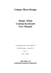
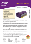
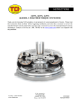
Unique Micro Design
Advanced Thinking Products
Model M331
Custom Desk Top
LCD Terminal
User Manual
Document Reference : DOC-M331-UM
UMD Part Number : 6-0331-993-3
Issue : 1
Revision : 31/05/95
... Technologists & Suppliers to Professional Systems Integrators ...
Revision History
Date
31/05/95
Issue
1
Comments
First Issue
Model 331 User Manual
Advanced Thinking Products ——
1. Introduction
This manual provides basic information about connecting to the
Unique Micro Design Model 331 Custom Desk Top LCD
Terminal, a member of the UMD ProtoLink Architecture family of
products.
The Model 331 is based on the UMD Model 301 Controller
Module which is also used internally in other products such as
custom keyboards, multi-in/out wedges, peripheral controllers and
custom VGA terminals.
In essence, the UMD ProtoLink Architecture is a versatile product
development system.
The architecture specifies the following:
• standard definitions for configuration parameters that can be
consistently used across a broad range of products.
• standard command set and peripheral control philosophy.
• standard set of hardware facilities which includes non-volatile
memory to hold configuration parameters, a peripheral
interface bus, serial ports which provide power for scanners
and bar code wand, display, external keyboard, keyboard
wedge and magnetic card reader interfaces.
• peripheral interface bus that allows the addition of other
modules to the core controller.
The UMD Model 301 Controller Module has extensive programmable
capabilities, which are not discussed in this manual (contact Technical
Support at Unique Micro Design for further information).
3
—— Advanced Thinking Products
Model 331 User
2. Custom Desk Top LCD Terminal Features
Custom Desk Top LCD Terminals are packaged in a wedge shaped
plastic housing. The Model 331 has flexible interfacing options
incorporating dual RS232 serial, AT keyboard interface, magnetic
card reader interface and bar code decoder. Power is sourced
externally from either a 5 Volt regulated or 7-9 Volt unregulated
supply.
The Model 331 features a 4 x 5 programmable keypad and 5
programmable LED indicators. Each key is programmable to return
user defined codes by downloading a text file via the keyboard or
serial port with details being permanently saved. There are no
configuration switches to be tampered with. The backlit liquid
crystal display ( LCD ) has 2 lines of 16 characters. The keypad uses
low travel mechanical keys which are sealed with a polycarbonate
overlay. This overlay is required to be preprinted.
As standard, all interfacing is achieved through a single DB25
socket connector, however we can easily accommodate various
connectors or cables to suit you application.
4
Model 331 User Manual
Advanced Thinking Products ——
Used in serial mode, a plug pack provides power to the unit. Any
key depression or bar code is output on a serial port. Any serial
input can be directed to the LCD display for operator information.
The second serial port is available for auxiliary I/O, eg with a
printer or bar code scanner.
In keyboard mode, the Model 331 can connect directly to the
keyboard port of a computer which provides the 5 volt power. In
this mode a further connection to a serial port is required to send
information to the LCD display.
Some options available include low cost bar code wand, a variety
of bar code scanners, magnetic card reader, keylock or "Touch
Memory" security. A customisation service is provided by Unique
Micro Design to meet specialised requirements.
5
—— Advanced Thinking Products
Model 331 User
3. Keyboard layout
From the factory, the keys in the keypad are programmed with
their row / column grid position, that is, the key at the top right
corner, when pushed outputs the string “A1”, the next key across
outputs “A2” and so on.
LED 5
LED 4
LED 3
LED 2
LED 1
a5
a4
a3
a2
a1
b5
b4
b3
b2
b1
c5
c4
c3
c2
c1
d5
d4
d3
d2
d1
M331 4 x 5 Keypad key and
LED locations
6
Model 331 User Manual
Advanced Thinking Products ——
4. Liquid Crystal Display ( LCD )
The LCD is a backlit 2 line by 16 character display. Input to the
LCD display is received through the serial ports. The display uses
simple cursor control consisting of the following :
Code
Hexadecimal
Description
BS
08
Backspace
LF
0A
Line Feed
CR
0D
Carriage Return
FF
0C
Form Feed
LCD Cursor Control Codes
BS Backspace
The BS control character moves the cursor one position to the left.
Any character located in the new cursor position is deleted. If the
cursor is already located at the far left-hand margin the display
ignores this instruction.
LF Line Feed
The LF control character sets the cursor to the next row in the
same column position. If the cursor is currently on the second row
that line of data is shifted up to the first row, deleting any data on
the first row.
CR Carriage Return
When the CR control character is sent, the cursor is positioned at
the left-hand margin of the current row. If the cursor is already at
the beginning of the row, the instruction is ignored
FF Form Feed
The FF control character clears the screen and sets the cursor to
the far left-hand margin, top row.
7
—— Advanced Thinking Products
Model 331 User
5. Connector Detail for M331
DB25S FEMALE
+V unregulated in 1
+5V regulated out 2
+5V 3
Computer Clock 4
Computer Data 5
Gnd 6
TxD1 7
RxD1
8
DTR1
9
CTS1 10
+5V 11
Default Switch 12
Reset Switch 13
14
15
16
17
18
19
20
21
22
23
24
25
Gnd
+5V
Keyboard Clock
Keyboard Data
Gnd
TxD 2
RxD 2
DTR 2
CTS 2
+5V
Bar code reader
Gnd
Looking at the DB25 socket on the M331
The M331 Interface Connector is a DB25 socket, providing
connections for power, default / reset switches and distributes the
signals for computer keyboard inputs, bar code reader and RS232
serial ports.
Contact Technical Support at Unique Micro Design, to discuss
your cabling requirements.
8
Model 331 User Manual
Advanced Thinking Products ——
6. Connection Example
The cable that connects to the M331 Interface Connector is wired
to suite your application. The example shown here provides power
using a plug pack and terminates the serial ports to look like
RS232 DB9 computer serial ports.
Plug Pack
DB9 Plug
Scanner Input
DB9 Plug
RS232 Input
9
—— Advanced Thinking Products
Model 331 User
6.1. Serial Ports
The serial interfaces use RS232 +/- 9 volt levels. Five volt DC
power is also provided on the interface to allow bar code scanners
to derive their power from the controller module.
The default communications parameters are 9600 baud, 8 data, no
parity and one stop bits.
Pin
1
2
3
4
5
6
7
8
9
I/O
i/p
o/p
o/p
o/p
i/p
o/p
Description
no connection
RxD
TxD
DTR
Ground
no connection
5 Volts
CTS
optional auxiliary power
Serial interface as shown in the
1
6
5
9
Front view of DB9 plug
10
Model 331 User Manual
Advanced Thinking Products ——
6.2. Connecting a Plug Pack to the M331 Interface Connector
The M331 can be powered by an unregulated power source of 6-9
volts rated at 1 amp. Note when a plug pack is used pins 2 and
3 on the interface connector must be joined..
The table below shows the connection details for an unregulated
plug pack.
Plug Pack
+ Volts
Gnd
Pin
1
14
M331 DB25 Connection
+ Volts unregulated in
Ground
2
3
+5 regulated out
5V DC
11
—— Advanced Thinking Products
Model 331 User
6.3. Computer and External Keyboard Interface
A standard PC keyboard may optionally be connected to the
external keyboard interface. Connection can also be made to the
M331 from the keyboard port of a computer, when connected, this
can supply power removing the need for a plug pack.
Pin
1
2
3
4
5
I/O
i/o
i/o
o/p
Description
Clock
Data
Reset
Ground
5 Volt DC
Keyboard interface 5 pin 180 degree DIN socket
1
3
5
2
4
Front view of 5 pin DIN socket
12
Model 331 User Manual
Advanced Thinking Products ——
The table below shows the connection details to connect the
M331 interface to a socket for a keyboard. Using UMD cable
CA202, a 5 pin DIN plug to 5 pin DIN plug, the M331 can be
connected to the keyboard port of a computer, derive power and
look like a keyboard. If power is connected in this way remove
jumper from pins 2 and 3 on interface connector.
Pin
1
2
3
4
5
I/O
i/o
i/o
o/p
Description
Clock
Data
Reset
Ground
5V DC
Pin
1
2
3
4
5
I/O
i/o
i/o
o/p
Description
Clock
Data
Reset
Ground
5V DC
—
—
Pin
4
5
—
—
6
3
—
—
Pin
16
17
—
—
18
15
M331 DB25 Connection
Computer Clock
Computer Data
N/C
Ground
5V DC
M331 DB25 Connection
Keyboard Clock
Keyboard Data
N/C
Ground
5V DC
Connection details to connect a
computer keyboard to the M331
13
—— Advanced Thinking Products
Model 331 User
6.4. Reset and Default Buttons
The reset button physically resets the microcontroller, forcing it to
perform a power up sequence.
The default button is used to return the non volatile configuration
memory back to the default settings. To use this facility, the
default button is held whilst pressing the reset button. Upon reset
the controller module will issue three rapid beeps to indicate that
the defaults have been set.
NOTE:
If any changes have been made to the programming of the Model
331, these will be lost when the reset to defaults sequence above is
used.
Default Switch 12
Reset Switch 13
25 Gnd
Wiring two normally open switches for default and
reset.
14
Model 331 User Manual
Advanced Thinking Products ——
7. Ordering information and Accessories
Part
Model
Number
Number
Description
M331 LCD Terminal (Multi function D25 output)
9-0331-100-1
K331-100
M331-S00 - No Lexan sheet
Customisation Service - Laminated self adhesive overlay sheets
Graphic set-up - (once only cost)
Item price - (per sheet)
Options
option Cx
Mag card reader (single track, x= 1,2 or 3)*
option Cy
Mag card reader (two track, y= 1&2, 2&3)*
Cables and accessories
Cable kit - (inc. plug pack,2 x serial cables)
1-6004-107-5
PP6D1000-E
Plug pack (for serial mode only)
DOC-M331-PD
Product description
Documentation
6-0331-992-5
6-0264-997-9
M264 programming kit
6-0331-993-3
DOC-M331-UM M331 user manual
7-5010-122-7
DOC-AN-122
Product overview: UMD Custom
Keyboards
7-5020-107-7
DOC-TN-107
UMD ProtoLink Architecture
15
... Technologists & Suppliers to Professional Systems Integrators ...
Unique Micro Design Pty Ltd ( ACN 007 419 490 )
Tel: +61-3-9764-8166
16 Nyadale Drive, Scoresby, Victoria 3179, Australia Fax: +61-3-9764-8177