1
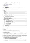
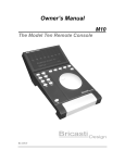
Unique Micro Design
Advanced Thinking Products
Model 231 & 232
Customer Displays
User Manual
Document Reference : DOC-M231-UM
UMD Part Number : 6-0231-993-0
Issue : 1
Revision : 7/08/95
... First Choice of Professional Systems Integrators ...
Revision History
Date
07/08/95
Issue
1
Comments
First issue in new format
Model 231/232 User Manual
——
1. Introduction
This manual provides basic information about connecting and
programming the Unique Micro Design Model 231 and Model 232
customer displays.
The Unique Micro Design Model M231 and Model M232
customer displays are attractive vacuum fluorescent units,
designed for all Point of Service applications. The M231 feature a
single line display of 20 characters, making it ideal for displaying
item prices at a check-out. The M232 features 2 lines of 40
characters for applications where the customer requires more
detailed information.
A feature of both displays is a stand alone carousel message mode.
In this mode, messages may be stored in non-volatile memory, to
be played back on call, or when the system is idle. This is excellent
for promotional and advertising messages. The stand alone
carousel message mode allows up to 8 separate messages to be
stored in non-volatile memory. These messages, may be up to 256
characters each, or longer text may flow to the next message area.
In this way it is possible to produce message sizes up to a single
message of about 2000 characters. These may then be replayed at
power up, when the system is idle, or when called by the software.
The M231 and M232 are available with either serial RS232C or
parallel interfaces. They are ideal for connection directly to a PC
port, the UMD M125ID intelligent cash drawers with the display
option, or any of the UMD ProtoLink family of products. Power
is provided from an external 9V DC plug pack which is supplied
with the unit.
3
——
Model M231 User Manual
2. Connector Details.
There are 2 connectors on the M23x displays. These are for
power and interface connection, and are at the rear of the
display’s base.
Power connector
Interface Connector
Reset
Location of connectors
2.1 Power interface connector
The display may be powered from either a 9V DC unregulated or
a 5V DC regulated power source. When a 9V supply is used, the
display provides a +5V DC regulated output on pin 4. (The 9V
plug pack is supplied as standard.) The power connector is a 270°
6 pin DIN socket configured as per diagram below.
Pin
I/O
Description
1
-
2
i/p
3
-
4
o/p
+5V DC regulated
out
5
i/p
+5v DC regulated in
6
-
5
Ground
1
6
Unreg +9V DC
reserved
4
2
3
As viewed from rear of
display
reserved
2.2 Reset button
The reset button physically resets the microprocessor, forcing the
controller to perform a power up sequence. It will not clear the
stored carousel messages.
4
Model 231/232 User Manual
——
2.3 Interface connection
The interface connector is a DB25 socket as pictured below.
Caution: As both serial and parallel versions of the display use a
DB25 connector, ensure a serial cable is used with the M23x-SM,
and a parallel cable for the M23x-PM.
13
1
25
14
Interface connector on rear of display base
2.4 RS232 Interface.
The serial connection is only available on the M231-SM and
M232-SM model displays.
Pin
2
3
4
5
7
16
17
20
I/O
o/p
i/p
o/p
i/p
i/p
i/p
o/p
Description
TxD (data out)
RxD (data in)
RTS (tied to +10V DC)
CTS
Signal ground
Data (sync mode) TTL level
Clock (sync mode) TTL level
DTR
DB25 female Serial Connections
Serial cable - CA205 (D9 to display)
D9F
TxD
CTS
DSR
SG
2
5
6
7
D25M
3
20
7
5
——
Model M231 User Manual
2.5 Parallel interface.
The parallel connection is only available on the M231-PM and
M232-PM model displays. The UMD cable CA139, shown below,
details the pin outs required.
PC parallel interface DB25M
Pin
1
2
3
4
5
6
7
8
9
10
11
12
13
14
15
16
17
18
19
20
21
22
23
24
25
6
M23x-PM parallel interface DB25M
Strobe
Data 0 (+)
Data 1 (+)
Data 2 (+)
Data 3 (+)
Data 4 (+)
Data 5 (+)
Data 6 (+)
Data 7 (+)
Acknowledge
Busy (+)
Paper end (+) tied low
Select (+) tied high
Autofeed (-)
Error (-) tied high
Initialise
Select input
Ground
Ground
Ground
Ground
Ground
Ground
Ground
Ground
Pin
1
2
3
4
5
6
7
8
9
10
11
12
13
14
15
16
17
18
19
20
21
22
23
24
25
Model 231/232 User Manual
——
3. Programming
The customer displays accept ASCII characters from their input
port. The on-board microprocessor interprets control codes and
UMD standard <DLE> commands, and performs the required
functions. All other ASCII characters are passed on to be
displayed.
3.1 Control Codes
These control the movement of the cursor and allow for the
selection of 2 different display modes.
The Model 231 and Model 232 customer displays respond
differently within these 2 modes.
M231 display modes
ASCII Hex Dec
Function
DC2
12
18 Horizontal scroll mode
When the cursor reaches the last position, all
characters are shifted to the left with the new
character displayed in the last position.
DC4
14
20 Auto carriage return mode
When the cursor reaches the last position, it is
repositioned to the first position without
performing a line feed, ie. doesn’t clear the
display.
7
——
Model M231 User Manual
M231 Control Codes
ASCII Hex Dec
Function
BS
08
8
The cursor moves 1 position to the left
(without deleting the existing character)
HT
09
9
The cursor moves 1 position to the right
(without deleting the existing character)
LF
0A
10 When in <LF> Valid mode
All characters are cleared while the cursor
position remains unchanged
When in <LF> Ignore mode
no effect - control code is ignored
FF
0C
12 Clears the display and cursor returns to the
home position
CR
0D
13 Moves cursor to the home position. (does not
clear display)
M232 Display Modes
ASCII Hex Dec
Function
DC2
12
18 Scroll mode
After all positions on the bottom line are
written, the bottom line scrolls up to replace
the top line and clears the bottom line. The
cursor is postitoined to the first position on
the bottom line.
DC4
14
20 Normal Mode
When the cursor reaches the end of the
second line, the cursor repositions to the first
position of the top line. The display is not
cleared, subsequent characters over-write the
existing displayed characters
8
Model 231/232 User Manual
——
M232 Control Codes
ASCII Hex Dec
Function
BS
08
8
The cursor moves 1 position to the left
(without deleting the existing character)
HT
09
9
The cursor moves 1 position to the right
(without deleting the existing character)
LF
0A
10 When in Normal mode
The cursor is moved to the same position on
the other line.
When in Scroll mode
When the cursor is on the bottom line, all
characters are shifted to the top line, the
bottomline is cleared with the cursor
remaining in the same position. When the
cursor is on the top line, the cursor simply
moves down to the same position on the
bottom line (over writes display, does not
clear the display)
When in <LF> ignore mode
no effect - the control code is ignored
FF
0C
12 Clears the display and cursor returns to the
home position, ie position 1 top line.
CR
0D
13 Moves cursor to the home position. (does not
clear display)
Note:
<LF> Ignore and <LF> Valid modes are selected by <DLE>
commands as described in the next section.
9
——
Model M231 User Manual
3.2 <DLE> Command Codes
ASCII HEX DEC
Function
<DLE
>
10
16
Pass single <DLE> to seleted destination
0
30
48
Output data to display (default device)
Ends store message command
4
34
52
Output data to the display
Ends store message command
5
35
53
Ends store message command
6
36
54
Ends store message command
>
3E
62
<LF> Ignore mode - (default for M231)
?
3F
63
<LF> Valid mode - (default for M232)
@
40
64
Enable XON/XOFF protocol (default)
A
41
65
Enable XON/XOFF protocol
N
4E
78
Store carousel message 0
O
4F
79
Disable display message 0 on power up
Q
51
81
Enable display message 0 on power up
R
52
82
Display carousel message 0
Ends store message command
S abcd
53
83
Interchange delay of ab.cd seconds
T abcd
54
84
Delay ab.cd seconds
X abcd
58
86
Position cursor at column ab line cd
na
6E
110 Store carousel message number “a”
ra
72
114 Display carousel message number “a”
10
Model 231/232 User Manual
——
<DLE> Commands
These are primarily used to program the carousel display
messages. The display’s internal microcomputer checks the data
for escape sequences. The escape character used by the display is
the ASCII Data Link Escape (<DLE>) control code character
(hex 10, decimal 16).
(<DLE>) - (10 Hex) - (16 Dec) - Pass single <DLE> to
selected destination
This is the escape character which tells the internal processor the
next sequence of data is a command and is therefore not passed
onto be displayed. The <DLE> command must preceed all the
commands in this section.
eg. To display carousel message 0 the ASCII command would be:
<DLE> 4 <DLE> R
This example first tells the processor to send all output to the
display (<DLE>4) then to output carousel message 0 (<DLE>R).
(0) - (30 Hex) - (48 Dec) Output data to display
It is necessary to tell the processor where to send the data. This
command directs the data to the default device which is in this
case is the display. It is not necessary to use this command each
time data is sent to the display. Once the processor is told to send
data to the display, all subsequent data will be directed to the
display until redirected by another command.
This command will also terminate the “Store carousel message”
comands (<DLE> N & <DLE> n a).
11
——
Model M231 User Manual
(4) - (34 Hex) - (52 Dec) Output data to the display
This command, as with <DLE> 0, directs all data to the display
(whether it is the default device or not)
This command will also terminate the “Store carousel message”
comands (<DLE> N & <DLE> n a).
(5) - (35 Hex) - (53 Dec) End store carousel message
command
This command will terminate the “Store carousel message”
commands (<DLE> N & <DLE> n a).
(6) - (36 Hex) - (54 Dec) End store carousel message
command
This command will terminate the “Store carousel message”
comands (<DLE> N & <DLE> n a).
(>) - (3E Hex) - (62 Dec) <LF> ignore mode
In this mode the display will ignore any Line Feed command. This
is the default setting for the M231 display. (Refer to the control
code section Page 8 of this manual for more detailed information.)
(?) - (3F Hex) - (63 Dec) <LF> Valid mode
In this mode all Line Feed commands are performed. This is the
default setting for the M232 display. (Refer to the control code
section Page 9 of this manual for more detailed information.)
(@) - (40 Hex) - (64 Dec) Enable XON/XOFF serial protocol
Enables XON/XOFF software handshaking. (Serial interface
displays only.)
(A) - (41 Hex) - (65 Dec) Disable XON/XOFF serial protocol
Disables XON/XOFF software handshaking. (Serial interface
displays only.)
12
Model 231/232 User Manual
——
(N) - (4E Hex) - (78 Dec) Store carousel message 0
This code tells the processor that all following data is to be stored
in carousel message area 0. Any previous messages stored in area
0 will be deleted. Data will be directed to this area until one of the
“End Store Carousel Message commands” is sent. (ie. <DLE> 0,
4, 5, 6, R or r.) Message areas hold a maximum of 256 characters.
If the data sent to a message area exceeds 256 characters, they
will over-run into the next message area.
(O) - (4F Hex) - (79 Dec) Display carousel message 0 on
power-up
It is possible to have the contents of message area 0 displayed
when the display is first turned on. This command disables this
feature.
(Q) - (51 Hex) - (81 Dec) Enable display carousel message 0
on power-up
When the display is turned on, it will, after initial self-diagnostics,
display the carousel message 0.
(R) - (52 Hex) - (82 Dec) Display carousel message 0
This command will display the contents of carousel message area
0. It will also end the “store carousel message” comands.
(S abcd) - (53 Hex) - (83 Dec) Interchange delay
This command sets the delay time before each individual character
is sent to the display. Delay times are in the order of ab.cd
seconds, where “abcd” are ASCII digits in a range of 0 to 9. eg
“<DLE>S 1900” means a delay of 19.00 seconds between the
display of each character. This command is cancelled by
specifying a delay of 00.00 secs. eg <DLE>S 0000.
Note: As the processor will normally execute <DLE> commands
immediately, it is necessary to embed them in a message with the
13
——
Model M231 User Manual
use of a second <DLE>. In this way, the delay will only take affect
at the correct point in the message. eg.<DLE> <DLE>S1900.
(T abcd) - (54 Hex) - (84 Dec) Delay ab.cd seconds
This command sets a delay time before the next character is sent
to the display or the next command is processed. Delay times are
in the order of ab.cd seconds, where “abcd” are ASCII digits in a
range of 0 to 9. eg “<DLE>T 1500” means a delay of 15.00
seconds before the next character is displayed.
Note: As the processor will normally execute <DLE> commands
immediately, it is necessary to embed them in a message with the
use of a second <DLE>. In this way, the delay will only take affect
at the correct point in the message. eg.<DLE> <DLE>T1500.
(X abcd) - (58 Hex) - (86 Dec) Position cursor
The cursor may be moved to any position with this command.
“abcd” is the location where ab represents the column number,
and “cd” the line number. “0000” represents the home position.
“abcd” are ASCII value from 0 to 9.
(n a) - (6e Hex) - (110 Dec) Store carousel message no. “a”
Use this command to store a message in any of the 8 message
areas where “a” is an ASCII character from 0 to 7. All subsequent
data is stored in the chosen message area. Previously stored data
is cleared.
(r a) - (72 Hex) - (114 Dec) Display carousel message no. “a”
This command is used to display a stored carousel message,
where “a” is an ASCII digit from 0 to 7.
It also ends the store carousel message command.
14
Model 231/232 User Manual
——
4. Default Modes
On power-up, or when the display is reset, the customer display
reverts to the following default settings.
M231 defaults:
•
•
•
•
horizontal scroll mode
<LF> ignore mode
XON/XOFF protocol enabled (serial interface displays only)
display carousel message “0” on power-up disabled
M232 defaults:
•
•
•
•
scroll mode
<LF> valid mode
XON/XOFF protocol enabled (serial interface displays only)
display carousel message “0” on power-up disabled
5. Carousel Messages
With the carousel message mode of operation, messages can be
stored in non-volatile memory for later play back. Any messages
stored will be retained permanently until over-written, even when
the display is turned off. This facility is useful for displaying
promotinal information during non-active periods.
5.1 Message areas
The carousel message memory is divided into 8 areas, numbered 0
to 7. Each seperate area can hold up to 256 characters.
Messages longer than 256 characters can be stored by one of two
methods.
• by imbedding “display message number a” commands within a
message.
15
——
Model M231 User Manual
or
• by over-running a message into an adjacent area. This is done
automatically if the mesage size is larger than 256 characters.
When a message over-runs into an adjacent area, the number for
the next message area is still sequential, ie. if a large message is
stored in message are “0”, the next message area is still “1”.
5.2 Clearing a carousel message area
Sending a “store carousel message” command to the display will
clear the contents of that message area. eg To clear message area
number 1 send <DLE>n1 <DLE>0. (<DLE>0 is used as an “end
store carousel message” command.)
5.3 Storing carousel messages
When storing a carousel message, the first data be sent to the
display should be a “Store carousel message” command, either
<DLE>N (store carousel message 0) or <DLE>n a (store carousel
message in area “a”). After the display receives this command, all
subsequent data will be stored in the specified message area (until
one of the “end store message” commands is received). It will also
clear any information currently stored in that message area.
Commands which are not required to be executed immediately (eg
<DLE>R, <DLE>T abcd, and others which are only to be
executed when the message is played back) must be embeded into
the message with the use of 2 <DLE> commands. eg To embed
a delay of 2.5 seconds into a carousel message, the format would
be “<DLE><DLE>T0250”
To endlessly repeat a message, a “<DLE><DLE>R” or
“<DLE><DLE>ra” command would be added to the end of a
message. In this situation, when the message reaches the end, the
embeded command will tell the display to display the message
again.
16
Model 231/232 User Manual
——
5.4 Displaying carousel messages
Carousel messages may be displayed on power-up, or when called
by the host system.
Message area 0 may be displayed at power-up by adding the
command <DLE>0 at the end of the message (before the “end
store message” command).
Any message area may be displayed with the use of the “display
message” command <DLE>ra, where “a” represents the message
area number to be displayed. Message area 0 may also be
displayed with the use of <DLE>R (“display message area 0”
command).
The display of a carousel message is ended whenever the display
receives characters from its input port. This means, if a carousel
messaging is taking place, it is recomended a <FF> be sent at the
start of a message to clear the display of any carousel message
information.
5.5 General Rules for Programming Carousel
Mesages:
When writing messages, the order of <DLE> commands is critical
to the correct operation of the carousel message. If a message
doesn’t display as expected, try rearranging commands.
• Begin with the “Store message command”
• Embed <DLE> commands within a message using 2 <DLE>
commands.
• To repeat the message continually, (until data is sent to the
display), embed a <DLE>R or <DLE>ra at the end of the
message, before the “End store carousel message” command.
• Use an “End stored message” command after all text is
entered. <DLE>0 or <DLE>4 are ideal as they also direct the
message to be output to the display.
• To display message 0 on power up, place a <DLE> Q after
“End store message” command.
17
——
Model M231 User Manual
6. Specifications.
Physical
Display
Overall dimensions
Base dimensions
Stalk dimensions
Display housing
Weight
Colour
Characters
Character size
Font
Power
Interface
18
M231
M232
280(w) x 233(h) x 105(d) mm
180(w) x 38(h) x 105(d) mm
50(w) x 100(h) x 25(d) mm
280(w) x 95(h) x 34(d) mm
1.4 kg
Beige
1 line x 20
2 lines x 40
characters
characters
6 x 9mm
3 x 5mm
5 x 7 dot matrix
9V DC @
9V DC @
600mA
800mA
Serial RS232C or parallel
Model 231/232 User Manual
——
7. Ordering information and Accessories
Part
Number
Model No.
9-0231-101-6
M231-SM
9-0231-201-2
M231-PM
9-0232-101-1
M232-SM
9-0232-201-7
M232-PM
2-5205-020-7
2-5281-020-9
CA210-2
CA281-2
2-5213-020-1
CA213-2
2-5139-020-6
1-6000-206-3
CA139-2
PP9D1000-D
6-0231-992-2
6-0231-993-0
DOC-M231-PD
DOC-M231-UM
Description
Displays
M231 - 1 x 20 display - serial
interface
M231 - 1 x 20 display - parallel
interface
M232 - 2 x 40 display - serial
interface
M232 - 2 x 40 display - parallel
interface
Cables and Accessories
Serial cable - D9 socket 2 metres
Serial cable - D25 socket 2
metres
Serial - to UMD M125-ID cash
drawer
Parallel cable - 2 metres
Plug pack 9V 1A
Documentation
Product Description
User manual (this document)
19
... First Choice of Professional Systems Integrators ...
Unique Micro Design Pty Ltd ( ACN 007 419 490 )
Tel: +61-3-9764-8166
16 Nyadale Drive, Scoresby, Victoria 3179, Australia Fax: +61-3-9764-8177