1
Model S143
UMD ProtoLink
Programming Utility
Technologists and suppliers to
professional systems integrators.
Unique Micro Design
Model S143
UMD ProtoLink Programming Utility
Program Version 1.4
24 August 1995
Issue 1
Unique Micro Design Pty Ltd
MC Box 1201
South East Mail Centre, Victoria, 3176
Australia
Tel +61 3 9764 8166
Fax +61 3 9764 8177
UMD reference : DOC-S143-UM
UMD part number : 9-3143-993-1
Copyright(c) 1995 Unique Micro Design Pty Ltd
Page 4
S143 User Manual
Unique Micro Design
S143 UMD ProtoLink Programming Utility
The S143 UMD ProtoLink Programming Utility is used to program the Unique Micro Design family
of UMD ProtoLink Products. This family includes the UMD Model 264 Custom Keyboard, UMD
Model 211 Custom LCD Terminal and others.
UMD ProtoLink Products contain non-volatile memory which holds configuration parameters and
keypad definitions. The S143 program allows you to easily view and edit this memory to configure the
UMD ProtoLink Product to suit your application. It also provides keypad testing and serial terminal
facilities.
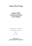
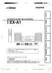
In the past, to program a UMD ProtoLink Product, an ASCII text editor was required to create a
“script file” which conformed to the UMD ProtoLink command set and configuration parameters. The
S141 or S142 Download Utility software would be used to program the UMD ProtoLink Products
using the script file. Refer to figure 1.
Text Editor
Program
C:>S142 DEMO.SCR
Creates/Edits
Reads
ASCII
Script
File
S141 or S142
Download Utility
Software
Downloads
UMD ProtoLink
Product
Figure 1
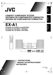
The S143 program addresses the issues of providing all the requirements to program the UMD
ProtoLink Products without the need to use external programs and be able to program the keypad
definitions and other parameters without consulting complex documentation. The user interacts with
this utility using menus. The S143 program can also be command line driven, which replaces the S142
software. The command line information is obtain by typing “S143 ?” at the DOS prompt.
S143 introduces a new concept in the programming of the UMD ProtoLink Products, that of the
“Initialisation file” (INI file). The INI file is a text file which holds a list of configuration settings set
out in an easily read format.
Unique Micro Design
Page 5
S143 User Manual
Backward compatibilty has not been forgotten: S143 can also transfer script files to the UMD
ProtoLink Product. Script files can be converted to INI files and vice versa.
Now with the S143 UMD ProtoLink Programming Utility, everything you need to program UMD
ProtoLink Products is integrated ino the one software package. Refer to figure 2.
Optio ns
U MD S1 43 M ain M enu
File
Edi t
Key
Link s
T ermi nal
Help
| Proto Link devi ce co nnect ed v ia>|
| PC CO M Po rt se tting s
>|
| Proto Link Firm ware optio n
>|
| ————— ———— ————— ————— ————— ———— ——-|
| [X] O verw rite Work Area
|
| [X] S ave Envir onmen t
|
| Advan ced Optio ns
>|
————— ———— ————— ————— ————— ———— ——-
Ex it
ASCII
Script
File
ASCII
INI
File
O ption s.
Read/Save
Work Area
Download
Option
S143
UMD ProtoLink
Programming
Software
Temporary
Work Area
Upload/Download
UMD ProtoLink
Product
Figure 2
Manual organisation
This manual describes how to install the ProtoLink Programming Utility and operate the S143
software to edit the “Key Definitions”. It is divided into the following sections
•
•
Section 1
Section 2
Installation
Quick Start
Page 6
S143 User Manual
Unique Micro Design
Section One
Installation
Page 8
S143 User Manual
Unique Micro Design
1. Requirements
You need the following to install the S143 program:
A personal computer (PC) with a ‘286 or higher CPU, 256K or more of RAM, a floppy and/or hard
disk drive, a monitor and a standard PC keyboard.
MS-DOS operating system, version 3.1 or higher.
2. Connection of UMD ProtoLink Product
There are two ways to program a UMD ProtoLink Product, either via the PC’s keyboard interface or
via a serial communication’s port. For most applications, the first method of interfacing is used, but
both are described here for completeness.
PC Keyboard Interface
Connection
UMD ProtoLink Product
1) Turn off the PC.
2) Disconnect standard PC Keyboard.
3) Referring to figure 3, connect one
end of the UMD CA202 or CA226
cable to the PC’s keyboard interface
connector.
4) Connect the other end of the
CA202 or CA226 cable to the 7 pin
DIN “Comp Ext Pwr” (Computer and
External Power) connector on the
UMD ProtoLink Product. Note that
the 5 pin DIN connector on the
CA202 or CA226 cable mates with 7
pin DIN connector.
5) Attach the standard PC Keyboard
to the 5 pin DIN “Ext Kbd” (External
Keyboard) connector on the UMD
ProtoLink Product. If the keyboard
uses a six pin mini DIN connector, you
will have to use a CA227 adapter to
convert the PC Keyboard’s connector
to that on the UMD Protolink
Product.
6) Turn on the PC.
Standard PC Keyboard
UMD CA202, 5 pin DIN to 5 pin DIN cable or
UMD CA226, 5 pin DIN to 6 pin mini DIN cable
PC Keyboard Interface
Figure 3
Unique Micro Design
Page 9
S143 User Manual
Serial Interface Connection
1) Turn off the PC.
UMD ProtoLink Product
2) Referring to figure 4, connect the
UMD CA201 or CA211 serial cable to
either the S1 or S2 serial port on the
UMD ProtoLink Product.
Power Pack
2) Connect the other end of the serial
cable to the COM1: or COM2: serial
port on the PC.
3) Connect the power pack to the 7 pin
DIN “Comp Ext Pwr” (Computer and
External Power) connector.
UMD CA201, DB9 to DB25 serial cable or
UMD CA211, DB9 to DB9 serial cable
4) Connect the power pack to the mains
power and turn it on.
5) Turn on the PC.
PC COM1: or COM2: Serial Interface
Figure 4
3. Installation of S143 Software
The S143 software may be run directly from the supplied floppy diskette, but it will run much faster if
you install the software on a hard drive if this is available. To do this, simply copy the files to an
appropriate sub-directory on your hard drive. This is achieved by running the batch file
“INSTALL.BAT”from the program diskette which executes the following commands for you:
C:
MD \UMD
CD \UMD
COPY A:*.*
Page 10
S143 User Manual
Unique Micro Design
Section Two
Quick Start
Page 12
S143 User Manual
Unique Micro Design
UMD ProtoLink Products contain non-volatile memory which holds configuration parameters and
keypad definitions. The S143 program allows you to easily view and edit this memory to configure
the ProtoLink Product to suit your application. It also provides keypad testing and serial terminal
facilities.
This quick start section provides an excercise on how to create a simple keypad layout definition.
1. S143 Basics
S143 is a DOS based program run from the DOS prompt. It cannot be run from MS-Windows if you
will be programming the UMD ProtoLink Product from the keyboard interface. (If you are
programming the ProtoLink Product via the serial interface, then you can run the S143 program from
MS-Windows either from a “DOS Box” or by running the “S143.PIF” file.)
Files S143.EXE, DEF_F00.INI and DEF_F02.INI need to be in the current working directory for
the program to operate.
To run the S143 program, simply type its name and press ENTER (ie ↵) from the intallation
directory:
C:\UMD> S143 ↵
S143 uses menus to list commands and options.
•
To select a menu option, use:
the LEFT (ie ï) and RIGHT (ie ð) ARROW keys.
•
To open a menu item either
press the ENTER (↵ )key whilst the menu item is highlighted
or
press the ALT key followed by the highlighted letter of the menu item, eg to open the Edit
menu use ALT+E.
•
To run a menu command
use the UP (ie ñ) and DOWN (ie ò) ARROW keys until you reach the item you want to
select and then press ENTER (↵ ) If the > symbol is present, it indicates that there is a
cascading menu to follow and it will open if the RIGHT ARROW (ð)or ENTER (↵ ) keys
are used. If the “...”symbol is present, this indicates that a dialog box will open when you run
this command.
•
To close the current menu
use the ESC key.
Unique Micro Design
Page 13
S143 User Manual
Menu options
UMD S143 Main Menu
Options
File
Edit
Key
Links
Terminal
|ProtoLink device connected via>|
|PC COM Port settings
>|
|ProtoLink Firmware option
>|
|——————————————————————————————-|
|[X] Overwrite Work Area
|
|[X] Save Environment
|
|Advanced Options
>|
——————————————————————————————-
Help
Exit
Indicates cascading menu
available
Open menu item
Options.
Figure 5
Page 14
S143 User Manual
Unique Micro Design
2. Selection of Type of Connection to UMD ProtoLink Product
After starting the S143 program, the first operation is to indicate which interface (keyboard or serial)
the UMD ProtoLink Product is connected to. This is done from the Options menu.
Select the Options menu from the main screen by pressing ALT+O or by moving the highlight to the
Options item and pressing ENTER (↵.) In either case, the Options menu is displayed, as shown in
figure 5.
Next open the “ProtoLink device connected via” menu item by pressing the DOWN ARROW (ò) to
highlight it and then pressing the RIGHT ARROW (ð) or ENTER (↵ ) keys to open it. The screen
in figure 6 is displayed. Use the UP (ñ) and DOWN (ò) ARROW keys to highlight the desired
option and select it by pressing ENTER (↵ ) or SPACE BAR keys. An (X) mark appears next to the
selected item. For example, if you have connected the UMD ProtoLink Product using the PC’s
Keyboard Interface, then select the “Keyboard Interface” option as shown.
UMD S143 Main Menu
Options
File
Edit
Key
Links
Terminal
Help
Exit
|ProtoLink device connected via>||(X) Keyboard Interface|
|PC COM Port settings
>||(.) COM 1 Port
|
|ProtoLink Firmware option
>||(.) COM 2 Port
|
|——————————————————————————————-| ——————————————————————
|[X] Overwrite Work Area
|
|[X] Save Environment
|
Selected
|Advanced Options
>|
——————————————————————————————-
Not Selected
Connection to PC’s Keyboard Port.
Current selection is via Keyboard Interface.
Figure 6
Unique Micro Design
Page 15
S143 User Manual
3. Keypad Layout Basics
CASH
UMD ProtoLink Products allow you to program
each key on the keypad to output the characters
you want.
As an excercise, we will
•
label key at grid position “e3” with the word
“CASH”
•
program this key to output the characters
“CASH” followed by the ENTER (↵ ) key
when pressed
•
also program the key to output the characters
“OUT” when released. Refer to figure 7.
CASH
Figure 7
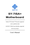
Grid reference a1
Grid reference
The position of a key on a UMD ProtoLink keypad
matrix is given by column and row grid reference,
as shown in figure 8. The first column is labelled
“a” and the first row is numbered “1”. So, the top
left key is grid reference “a1”, the next key along
the top is “b1” and so on.
Column a
b
c
Row 1 Void
7
8
9
2 Yes
4
5
6
No
1
2
3
0
00
.
3
4
d
e
CASH
Grid reference e3
Figure 8
CASH
Make and break codes
Each key has two sets of characters programmed
for it, one set (“make codes”) are sent on pressing
a key. The other set (“break codes”) are sent on
releasing the key. This is outlined in figure 9.
Each make and break sequence can send upto 255
characters. Break codes are usually not required in
the majority of applications.
Key "e3" definition make code sequence =
"CASH" Ã
break code sequence =
"OUT"
e3
Press
CASH
e3
Key pressed - make codes sent =
"CASH" Ã
Release
CASH
e3
Key released -break codes sent =
"OUT"
Figure 9
Page 16
S143 User Manual
Unique Micro Design
4. Edit Key Definitions
To start entering or editing key definitions, select the Key menu and run the Edit Key Definitions
command. You will be greeted with the Edit Key Definitions screen as shown in figure 10.
Edit Key Definitions
Edit
Layer
Options
Show
Help
Close
|Layer...
|
€L1|LED Number...|
a1 ————————————- 1 f1 g1 h1 i1 j1 k1 l1 m1 n1 o1 p1 q1 r1 s1
| || || || || || || || || || || || || || || || || || || |
-— —- —- —- —- —- —- —- —- —- —- —- —- —- —- —- —- —- —a2 b2 c2 d2 e2 f2 g2 h2 i2 j2 k2 l2 m2 n2 o2 p2 q2 r2 s2
| || || || || || || || || || || || || || || || || || || |
-— —- —- —- —- —- —- —- —- —- —- —- —- —- —- —- —- —- —a3 b3 c3 d3 e3 f3 g3 h3 i3 j3 k3 l3 m3 n3 o3 p3 q3 r3 s3
| || || || || || || || || || || || || || || || || || || |
-— —- —- —- —- —- —- —- —- —- —- —- —- —- —- —- —- —- —a4 b4 c4 d4 e4 f4 g4 h4 i4 j4 k4 l4 m4 n4 o4 p4 q4 r4 s4
| || || || || || || || || || || || || || || || || || || |
-— —- —- —- —- —- —- —- —- —- —- —- —- —- —- —- —- —- —a5 b5 c5 d5 e5 f5 g5 h5 i5 j5 k5 l5 m5 n5 o5 p5 q5 r5 s5
| || || || || || || || || || || || || || || || || || || |
-— —- —- —- —- —- —- —- —- —- —- —- —- —- —- —- —- —- —a6 b6 c6 d6 e6 f6 g6 h6 i6 j6 k6 l6 m6 n6 o6 p6 q6 r6 s6
| || || || || || || || || || || || || || || || || || || |
-— —- —- —- —- —- —- —- —- —- —- —- —- —- —- —- —- —- —a7 b7 c7 d7 e7 f7 g7 h7 i7 j7 k7 l7 m7 n7 o7 p7 q7 r7 s7
| || || || || || || || || || || || || || || || || || || |
-— —- —- —- —- —- —- —- —- —- —- —- —- —- —- —- —- —- —a8 b8 c8 d8 e8 f8 g8 h8 i8 j8 k8 l8 m8 n8 o8 p8 q8 r8 s8
| || || || || || || || || || || || || || || || || || || |
-— —- —- —- —- —- —- —- —- —- —- —- —- —- —- —- —- —- —Keyboard Header Information.
Current Key:a1(#1 ) Make : 0
“”
Layer No.:1 of 1
Break: 0
“”
Kbd ID: 1
Number Keys: 128 LED Number: 1
Layout: UMD 128
Figure 10
Next, open the Edit menu and run the “Layer” command. At this stage the help line will display:
Use
áâàß,[PgDn],[PgUp]
change layer,[ENTER] to edit,[F10] Show,[ESC] Close.
At this stage pressing the F10 function key will change the screen to only show keys that have been
defined. This display mode may be preferrable. Pressing the F10 function key again will revert to the
original display mode.
In either instance, the first key in the keypad grid, key “a1”, will be highlighted. Move the highlight to
grid location “e3” by using the ðARROW key four times then the ò ARROW key twice. The
“Current Key” field in the “Keyboard Header Information” area at the bottom of the screen indicates
that key “e3” is selected.
To edit the highlighted “e3” key, press the ENTER (↵ ) key.
Unique Micro Design
S143 User Manual
Page 17
The cursor will now be placed in the “Make :” field at the bottom of the screen. Type in the text that
you want sent when this key is pressed. In this example, the word “CASH”. As we want to also send
the ENTER (↵ ) character at end of the word “CASH” we need to enter this special key. This will be
explained more fully later, but for now simply type the four characters “<ENT” and then press the
ENTER (↵ ) key to accept. Notice that “CASH\r” is now displayed. To finish the entry of this Make
field, press the ENTER (↵ ) key once again.
After entry of the “Make” field, the cursor will now be placed in the “Break :” field. Type the word
“OUT” followed by pressing the ENTER (↵ ) key to accept this entry. The grid location “e3” on the
screen will now change to a different colour to indicate that it has been defined. Once the ProtoLink
keyboard is programmed with this definition, the letters “OUT” will be sent when key “e3” is released.
Whilst entering key definitions, the following editing keys may be used:
•
•
•
•
•
•
•
•
•
•
: deletes the character before the cursor
: deletes the character under the cursor
: takes the cursor to the beginning of the field
: takes the cursor to the end of the field
: finishes the entering of characters
: cancels the operation (returns key definition to its
original value and places the cursor back to the keypad grid.)
Left & right (ïð) : move the cursor along the field
Up & down (ñò)
: moves the cursor between the make and break field definitions
<
: enter special keys
{
: enter ProtoLink commands
Backspace
Delete
Home
End
Enter
Esc
Entering special keys
Most Special keys may be entered into key definition fields directly by simply pressing them. This
includes keys such as function keys, insert, page up, page down etc.
Some special keys, for example, ENTER (↵ ), DELETE, HOME, END, BACKSPACE and ARROW
KEYS cannot be entered directly as they are used in the editing process. To insert these keys into the
key definition field, type the “<“ character followed by the name of the special key, eg “HOME” for
the HOME key, followed by pressing the ENTER (↵ ) key to accept the entry.
To see a list of available special keys, press the “F1” function key after you have typed the “<“
character. The following help screen, figure 11, will be shown. This screen provides an easy way to
enter special keys. Here one simply uses the cursor keys to move the highlight to the desired key
followed by pressing the ENTER (↵ ) key to select it. If an Alt, Ctrl or Shift modified special key is
desired, simply press the Alt, Ctrl or Shift keys to enable or disable the shift mode which will be
displayed in the “Shift key state” area.. The ESC key is used to exit this option without a selection.
So, in our “CASH” key example, we desire to insert the ENTER (↵ ) key at the end of the word
“CASH” using the alternative help screen method. Type “CASH<“ into the make string and then
press the F1 function key. The cursor should be highlighting “Enter” by default as shown in figure 11.
Simply press the ENTER (↵ ) key to accept this special key entry afterwhich “CASH\r” will be
displayed; the “\r” being short hand for ENTER (↵ ). Now finish this key entry by pressing the
ENTER (↵ ) key once again.
Page 18
S143 User Manual
Unique Micro Design
Edit Key Definitions
Edit
Layer
Options
Show
Help
Close
——————————————————————————————-Special Keys———————————————————————————————————|ASCIIDel
Down
F10
RShiftMak Pad1
Use cursor keys to high- |
|Tab
PgDn
F11
RShiftBrk Pad2
light the desired key.
|
|Null
Ins
F12
NumLock
Pad3
Press [Enter] to select
|
|BS
Del
LAltMak
CapsLock
Pad4
or [Esc] to exit.
|
|Enter
F1
LAltBrk
ScrollLock Pad5
|
|Esc
F2
RAltMak
PrtScr
Pad6
Shifted keys can also be |
|Space
F3
RAltBrk
Pause
Pad7
used. Pressing the [Alt], |
|Home
F4
LCtlMak
Pad*
Pad8
[Shift] or [Ctrl] key will|
|Up
F5
LCtlBrk
PadPad9
enable/disable that shift |
|PgUp
F6
RCtlMak
Pad/
Pad9
key if allowed.
|
|Left
F7
RCtlBrk
PadEnt
|
|Right
F8
LShiftMak
Pad0
|
|End
F9
LShiftBrk
|
|
|
|
Shift key state : none
Special Key is <Enter>
|
———————————————————————————————————————————————————————————————————————————————
| || || || || || || || || || || || || || || || || || || |
-— —- —- —- —- —- —- —- —- —- —- —- —- —- —- —- —- —- —Use àß,[SHIFT],[ALT],[CTRL] shift special key.[ENTER] to select,[ESC] Exit.
Current Key:e4(#36 ) Make : 8
“HELP” <>
Layer No.:1 of 1
Break: 0
“OUT”
Kbd ID: 1
Number Keys: 128 LED Number: 1
Layout: UMD 128
Figure 11
Finishing Key Definition
Once you have finished entering all the key definitions, close the Edit Key Definitions screen by
pressing ALT+C.
Unique Micro Design
S143 User Manual
Page 19
5. Saving Your Work
The S143 program uses the computer’s memory as a work area. The work area is manipulated by the
actions of the user by either using the work area editor or menu operations. For example, the keypad
definitions that you entered in the previous section are stored temporarily in the work area.
ASCII
INI
File
Save
Work Area
to INI file
S143
UMD ProtoLink
Programming
Software
Temporary
Work Area
Upload/Download
UMD ProtoLink
Product
Figure 12
Once you have finished entering the key definitions, the next step is to save your work. This is done
from the main menu item, File. All of the File sub-menu choices are given below with the ones
relevant to saving being highlighted:
•
•
•
•
•
•
•
Read .INI file to Work Area...
Read Script file to Work Area...
Save Work Area to .INI file...
Save Work Area to Script file...
Upload ProtoLink device to Work Area...
Download Work Area to ProtoLink Device...
Download Script file to ProtoLink Device...
Page 20
S143 User Manual
Unique Micro Design
To save your work as an “INI” file, run the “Save Work Area to .INI file...” command. The “Save
INI file” dialog box will open, prompting you to enter a file name. Type in a valid DOS file name, ie
up to eight characters with the first character being alphabetic (ie ‘A’ to ‘Z’) followed by pressing the
ENTER (↵ ) key. There is no need to type the “.INI” file extension as this is automatically added.
The TAB key can be used at this stage to move into the directory list which allows you to select an
existing file to use or to move through directories by selecting the <DIR> entries.
Once a filename has been entered, you will then be asked to type in a comment for the file if desired,
afterwhich the file will be saved.
Options
UMD S143 Main Menu
File
Edit
Key
Links
Terminal
|Read .INI File to Work Area...
Save INI File
Help
Exit
|
|
|
|
|
| Enter the .INI File Name to Save (.INI Extension not needed)|
| or [TAB] to swap to directory.
|
|
|
| File Name: D:\PROJS\S143\EXA1
|
|
|
| Directory of D:\PROJS\S143\*.INI
|
|
|
| ..
<DIR>
|
| DEF_F00.INI
2018
|
| DEF_F02.INI
2018
|
| EXA1.INI
120
|
|
|
——————————————————————————————-—————————————————————————————-
Select file to Read or Save.
Work Area Last Data: DEF_F00.INI
F/w date 18/5/95.
Figure 13
Unique Micro Design
S143 User Manual
Page 21
6. Programming the UMD ProtoLink Product
UMD ProtoLink Products contain non-volatile memory which holds configuration parameters and
keypad definitions. Information is “downloaded” into a UMD ProtoLink Product by issuing memory
write commands, eg “write value 10 into location 240”.
The S143 software programs UMD ProtoLink Products by either:
•
downloading a script text file which contains raw memory write (and other) commands
or
•
downloading the S143 Work Area, which is essentially a copy of the UMD ProtoLink
Product’s non-volatile configuration memory.
Note that INI files cannot be directly downloaded, but must be first “read into” the S143 Work Area
and after that the Work Area downloaded.
S143
UMD ProtoLink
Programming
Software
Temporary
Work Area
Download
UMD ProtoLink
Product
Figure 14
Programming UMD ProtoLink Products is done from the main menu item, File. The relevent File
sub-menu choices are highlighted here:
•
•
•
•
•
•
•
Read .INI file to Work Area...
Read Script file to Work Area...
Save Work Area to .INI file...
Save Work Area to Script file...
Upload ProtoLink device to Work Area...
Download Work Area to ProtoLink Device...
Download Script file to ProtoLink Device...
Page 22
S143 User Manual
Unique Micro Design
To program the work that you have done so far into the UMD ProtoLink Product, run the
“Download Work Area to ProtoLink Device...” command. This assumes, of course, that the S143
work area has valid data in it. The “Download Work Area to ProtoLink Device” dialog box will open,
informing you of the connection to be used (ie either the keyboard interface or serial port). You are
asked to make a selection of:
•
•
•
‘D’ Download Work Area parameters that are DIFFERENT from defaults.
‘A’ Download ALL of the Work Area, defaults included.
ESC to close this dialog.
Press the ‘D’ key to begin the download operation.
If the connections are correct, the download will proceed. After it is finished, the UMD ProtoLink
Product will be issued a reset command which will re-initialise the product making it take up the new
configuration from its non-volatile memory.
7. Show Keys
Once the UMD ProtoLink Product has been programmed, the Show Keys command can be run from
the Keys main menu item. This screen will show every active key that is pressed.
Continuing on with our example, pressing the “e3” key should show “C A S H \r” on the Show Keys
screen and “O U T” when the key is released.
8. Summary
This Quick Start section has taught you :
A
B
C
D
E
F
G
how to use the menu system in the S143 software
about keypad grid references
about make and break codes
how to edit key definitions and enter special keys
how to save your work to an INI file
how to program a UMD ProtoLink Product
how to check your keypad definitions.
This Quick Start section should cover the majority of your needs.
Unique Micro Design
S143 User Manual
Page 23
... Technologists & Suppliers to Professional Systems Integrators ...
Unique Micro Design Pty Ltd ( ACN 007 419 490 )
16 Nyadale Drive, Scoresby, Victoria 3179, Australia
9-3143-993-1
Tel: +61-3-9764-8166
Fax: +61-3-9764-8177
DOC-S143-UM Issue 1 - 24/08/95