1
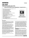
Ohaus Corporation
29 Hanover Road
Florham Park NJ
07932-0900
FIELD TEST SCALE
Models 2400-11 and 2400-12
Instruction Manual
1
INTRODUCTION
This manual covers Installation and Operation for the Ohaus Field Test Scale, Models
2400-11 and 2400-12.
DESCRIPTION
The Field Test Scale is a very compact design and provides accurate weighings of a wide
variety of heavy materials, even under the most adverse conditions. Applications
include: road constructions sites, weighing of soil samples, archaeological samples, and
mineral samples. The Field Test Scale is ruggedly built and designed for field
applications where accurate measurements must be made. The large stabilized pan will
hold oversized samples without tipping, and the weighted base keeps the entire scale
rock steady. Model 2400-11 permits readings up to 500 g taken from a single slidingweight beam with a readability of 5 g. A set of slotted weights, stored in the base, extend
the capacity up to 16 kg. Model 2400-12 has a capacity of 36 lb with a readability of 0.01
lb.
Figure 1. Field Test Scale with Slotted Weight Set.
2
SCALE COMPONENTS
Figure 2 illustrates the various components of the Field Test Scale. Refer to this figure
when assembling the scale after unpacking.
Figure 2. Field Test Scale Components.
The Field Test Scale is equipped with a universal beam, graduated in both avoirdupois
(A) and metric (B) calibrations. The appropriate scale to be used is determined by the
attachment weight calibration (avoirdupois or metric).
Figure 3. Beam Graduations.
3
UNPACKING
Carefully unpack the Field Test Scale as
follows:
1.
Refer to Figures 4, 5 and 6.
2.
Remove attachment weight hanger C.
3.
Remove insert D.
4.
Remove insert E which surrounds the
base.
5.
Remove insert F which contains the
beam assembly.
Figure 4.
6.
Remove box H containing attachment
weights.
7.
Remove scale base I.
8.
Finally, lift the bottom insert and remove the scale pan.
Figure 5.
Figure 6.
4
ASSEMBLING THE FIELD TEST SCALE
Refer to Figure 7 when assembling the Field Test Scale.
1.
Remove screws from bearing covers and slip covers off center post N.
NOTE
NOTE: Be careful not to lose screws, covers and thrust plates.
2.
Remove tape from loop J and remove pin. Save the pin.
Figure 7. Base Assembly.
3.
4.
Hold beam assembly O in position
shown in Figure 7 and lower loop J
through the hole in the base. Be sure
loop stop k swings under base stop L
and then lower beam assembly so
that fulcrum pivots M rest in center
post.
THRUST PLATE
Position the black thrust plates in the
center post slots as shown in Figure
8.
5.
Slip the bearing covers back into place
over center post N.
6.
Replace screws and tighten in place.
7.
Screw on scale plate.
8.
Now carefully invert the scale as
shown in Figure 9.
Figure 8. Bearing Covers.
Figure 9. Scale Inverted.
5
ASSEMBLING THE FIELD TEST SCALE (CONT.)
9.
Swing check line P into slot in loop and replace pin Q
Q. (NOTE: Be sure pin also
goes through the hole in the check link.
10. Use a screwdriver to bend over pin Q which projects from loop. (NOTE: Position
screwdriver as shown and hit firmly with hand to bend pin.)
11. Return scale to upright position.
12. Place attachment weight hanger in loop and weights on weight rack as shown in
Figure 10.
The Field Test Scale is now ready for use and should look like Figure 10.
Figure 10. Assembled Field Test Scale.
WEIGHING
1.
Set the scale on a reasonably level surface. The level condition is not critical,
however, it should not be obviously badly out of level.
2.
The scale is in balance when the beam oscillates between the limiting stops.
Adjust the zero balance before beginning to use the scale so that the beam will
oscillate in that manner, that is with the poise set to the left side of the beam. For
adjustments to zero the scale, turn the balance compensation weights on the left
end of the beam (knurned nuts).
3.
To weigh, place the object on the pan, slide the poise on the beam to a position
to cause the beam to oscillate between the stops. If the item being weighed
exceeds the beam capacity, add sufficient slotted attachment weights to cause
the end of the beam to move down. Then slide the poise back on the beam until
a balanced condition is achieved. The weight is the value of the total accumulation
of attachment weights plus the value read from the position of the poise on the
beam.
6
TRANSPORTING THE SCALE
The Field Test Scale is portable and can be moved from place to place without damage.
A handle has been provided in the back edge of the base. When transporting the scale,
pick it up by the handle, not by the scale beam ot the platform pan assembly. Be sure
to remove the attachment weights and the attachment weight hanger before picking up
the scale.
CARE AND MAINTENANCE
With reasonable care, your Field Test Scale can be kept in good working order.
1. Avoid severe impacts to the platform or the beam.
2. Keep the scale clean. Foreign material should not be permitted to accumulate
in the pivot and bearing areas.
3. Never apply oil or any lubricant to the pivots or bearings.
REPLACEMENT PARTS
Part No.
500 Gram Slotted Attachment Weight
1 Kg Slotted Attachment Weight
2 Kg Slotted Attachment Weight
5 Kg Slotted Attachment Weight
1 Lb Slotted Attachment Weight
2 Lb Slotted Attachment Weight
5 Lb Slotted Attachment Weight
10 Lb Slotted Attachment Weight
Weight Hanger Assembly
Pin
Check Link
2420-20
2241-21
2240-20
2239-20
2421-20
2237-21
2422-20
2235-20
2428-00
P6113-05
2404-00
SERVICE INFORMATION
For Service assistance in the United States, please call Ohaus Corporation toll-free
at (800) 526-0659. An Ohaus Product Service Specialist will be available to help you.
7
LIMITED WARRANTY
Ohaus products are warranted against defects in materials and
workmanship from the date of delivery through the duration of the
warranty period. During the warranty period Ohaus will repair, or, at its
option, replace any component(s) that proves to be defective at no
charge, provided that the product is returned, freight prepaid, to
Ohaus.
This warranty does not apply if the product has been damaged by
accident or misuse, exposed to radioactive or corrosive materials, has
foreign material penetrating to the inside of the product, or as a result
of service or modification by other than Ohaus. In lieu of a properly
returned warranty registration card, the warranty period shall begin on
the date of shipment to the authorized dealer. No other express or
implied warranty is given by Ohaus Corporation. Ohaus Corporation
shall not be liable for any consequential damages.
As warranty legislation differs from state to state and country to
country, please contact Ohaus or your local Ohaus dealer for further
details.
Ohaus Corporation
29 Hanover Road,
Florham Park, NJ 07932, USA
Tel: (973) 377-9000,
Fax: (973) 593-0359
With offices worldwide.
P/N 2402-01 R1095 © Ohaus Corporation 1995, all rights reserved.
8