1
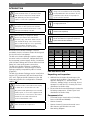
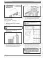
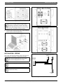
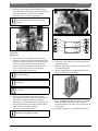
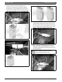
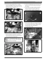
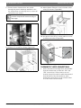
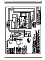
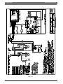
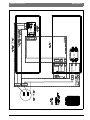
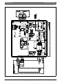
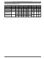
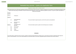
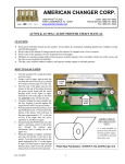
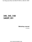
SM Series Electric Heat Kit HK050 | HK100 | HK150 | HK200 | 8 733 904 449 (2013/12) Installation Manual 2| SM Series Electric Heat Contents INTRODUCTION ......................................................3 PRE-INSTALLATION.................................................3 Electric heat kit.......................................................4 installation - hardware ............................................5 installation - wiring .................................................6 Thermostat wire connections ...............................10 Site line voltage connection..................................11 Wiring diagram replacement .................................11 Unit start up..........................................................11 Wiring diagram......................................................12 Electric heat electrical data ..................................17 8 733 904 449 (2013/12) Subject to change without prior notice SM Series Electric Heat SM Series Electric Heat INTRODUCTION | 3 INTRODUCTION The SM series HK Series Heater package is designed for installation in the heat pump model published in this document. Do not install this heater kit in a heat pump not specified in this manual. Installation and servicing of this equipment can be hazardous due to system pressure and electrical components. Only trained and qualified personnel should install, repair, or service the equipment. HK Series Heater Package can only be installed on single phase units Before performing service or maintenance operations on the system, turn off main power to the unit. Electrical shock could cause personal injury or death. A heater collar is installed in the SM models, no need to order separately. When working on equipment, always observe precautions described in the literature, tags, and labels attached to the unit. Follow all safety codes. Wear safety glasses and work gloves. Use a quenching cloth for brazing, and place a fire extinguisher close to the work area. Bosch HK Series Heater Package is a field Installable electric resistance heater kit designed for the SM series heat pumps. The HK series heater package requires separate electrical service connection, independent from the heat pump’s power supply. Hence, installation of this Heater Package will convert SM Series Heat Pump into a two point power connection. The HK series Heater Package is available in several kW capacities. Unit tonnage vs Heater Package capacity compatibility table is below. (Figure#1) The HK series Heater Package can be installed on Vertical (VT), Horizontal (HZ) and Counter-flow (CF) units. Eight and ninth character of the SM heat pump signifies the configuration. Example: SM024-1VTC. Improper installation of the electric resistance heater can result in severe injury or death due to electrical shock or fire. Only trained and qualified personnel should install, repair, or service this equipment. All electrical service connection to the heater must be done to National and local electrical Standard & codes. DO NOT wire the heater elements into the same circuit as the compressor. SM Series Electric Heat A heat pump thermostat with supplemental electric heat feature is required to operate the system when this kit is installed. Figure 1: HEATER COMPATIBILITY Unit Model HK0501201 (5kW) HK1001201 (10kW) HK1501201 (15kW) HK2001201 (20kW) SM024 X SM036 X X SM048 X X SM060 X X X X SM070 X X X X x Heater Package Compatibiity PRE-INSTALLATION Unpacking and inspection 1. UNPACK the HK heater kit and inspect for contents and condition. If any part or the kit appears damaged (i.e.: broken heater elements, damage relays) or missing, do not attempt to install the kit. Contact your local distributor for further help. 2. Ensure that the heater kit package includes the following components. Contact your local distributor for further help. Components List • • • • • Pre-wired heater electrical box (including fuses on HK150 and HK200) Heater elements Heater element(s) protective metal cover Wire harness pre-wired at one end . New wiring diagram 8 733 904 449 (2013/12) 4 | electric heat kit • • SM Series Electric Heat Adhesive back electrical data label Clear hardware accessory bag containing: • Heater element mounting screws (4 for each element bank) • Heater element cover mounting screws (2 for each cover) • Four electrical box mounting screws • Push in wire ties • This installation manual For technical assistance contact your local distributor or Bosch Technical Support: (954) 776-5471 or [email protected]. Figure # 3 Required Tools • • • • • • • Phillips screwdriver Small flat head screwdriver 5/16” socket and a ratchet or drill Wire cutter Wire stripper Torque Phillips head screwdriver Multi meter ELECTRIC HEAT KIT The Electric Heat field installed kit contains two main electrical enclosures: Electric Heat Control Box and Electric Heat Elements, both are located in the blower compartment. (Figure#2 through #6) The control box attaches to the corner post and the heat elements to the blower heater collar in the blower compartment. Figure # 4 Figure # 5 Figure # 2 8 733 904 449 (2013/12) Subject to change without prior notice SM Series Electric Heat SM Series Electric Heat installation - hardware | 5 5. Remove the heater collar cover plate(s). (Figure#8) Figure # 8 Figure # 6 [1] Heating element cover [2] Electric Heat control box INSTALLATION - HARDWARE 1. At Thermostat Turn system to “OFF” 2. Turn the main power to the heat pump to “OFF” at the unit’s disconnect switch or breaker panel. 6. In preparation for heater element installation orient the heating elements with thermal overloads (cutouts) are on the right side for VT & CF and top for HZ.(Figure#9) Proper Thermal Overloads (cutouts) orientation is required for safe unit operation. Follow proper lockout/tag out procedure. 3. Prior to removing the blower panel, disconnect unit display from the back of the panel.(Figure#7) Figure # 7 4. Remove the access panel(s) from the unit exposing the blower section and compressor section of the packaged heat pump unit. Figure # 9 7. Insert heating element(s) into collar. Heating element rods must be inserted into inner most holes as shown in Figure#10. This will support and prevent vibration of heater elements. SM060 and SM070 models will have an additional extension bracket mounted on each cover plate. Heating element rods must be aligned to extension brackets accordingly. SM Series Electric Heat 8 733 904 449 (2013/12) 6 | installation - wiring SM Series Electric Heat Figure # 10 If only one heating element is being installed, install in into the position closest to the blower wheel. Remaining opening to be covered using (1) of the cover plates removed in step 5. Figure # 12 5kW-10kW (HK050-100) Control Box 8. Secure each insert(s) with four of the supplied sheet metal screws (Figure#11). Figure # 11 Figure # 13 15kW-20kW (HK150-200) Control Box INSTALLATION - WIRING TO CONTROL TO BLOWER SIGNALS MOTOR POWER There are two Electric Heater control box layouts depending on HK model. (Figures#12 & #13) HR1 controls Heating Elements 1 and 3 and HR2 controls heating elements 2 and 4. ATTACH TO ELECTRICAL HEAT BOX J12 J19 J39 Refer to wiring diagram on Pg12. Electric Heater control box is completely prewired from the factory. TRANSFORMER POWER Figure # 14 Electric Heat Harness 8 733 904 449 (2013/12) Subject to change without prior notice SM Series Electric Heat SM Series Electric Heat installation - wiring | 7 1. Route the high voltage Red and Black wires, originating from the Electric Heater control box through grommets in the Electric Heater Element cover as show in Figure#15. Route all Red wired together through the same grommet and black wires through the second grommet. la Figure # 16 1 2 Figure # 15 [1] Red wire [2] Black wire 2. For Vertical (VT) and Horizontal (HZ) units install the heater control box between the unit corner posts at the bottom of the of the blower section. Counter flow (CF) units install the heater control box between the unit corner posts at the bottom of the of the blower section. (Figure#2 through #6) Orient the heater control box with contactor(s) towards the bottom. Figure # 17 4. Install the cover for the control box with the provided screws. 5. Remove and retain cork tape covering the hole in the divider panel. 6. On the wiring harness supplied with this kit identify J39 plug. (Figure#18) Holes for Control Box are pre-punched in the corner post. Ensure no wires are pinched between the metal parts 3. Connect red and black high voltage wires originating from Electric Heater control box to the Electric Heater elements as shown in Figure#17. Terminate Black wires labeled HLS at the thermal limits (cutouts) and Red wires labeled HT at the heater element connections.(Figure#16 ) Figure # 18 7. Route J39 plug through the hole in the divider panel and mate the plug to the receiving connector P39 on the side of the electric heat control box. 8. Re-apply cork tape to the divider panel hole. Each wire is labeled for ease of identification. Reference wiring diagram on Pg12. SM Series Electric Heat 8 733 904 449 (2013/12) 8 | installation - wiring 9. SM Series Electric Heat Route the other end of the harness (3 connector end) along the already installed blower harness, and terminate it at the unit electrical box (E-Box). Use tie-wraps every 1218 inches for a neater finish. (Figure#19- #21) Figure # 21 Transformer Power 10. In the heat pump electrical box, disconnect the J19/P19 high voltage wires that connect the blower motor to the “line voltage” these wires are located on the left hand side of the e-box shown in the picture below.(Figure#22) Figure # 19 J19 Blower Power Plug (two position) Figure # 22 11. Mate J19 plug originating from the electric heat control box (red and black wires) with P19 plug originating from blower harness at EBox.(Figure#23) When mating plugs, push both connectors together until they snap with a click. Figure # 20 P12 Control Signal Plug (three position) Figure # 23 8 733 904 449 (2013/12) Subject to change without prior notice SM Series Electric Heat SM Series Electric Heat 12. Disconnect the red and black line voltage harness (8733901778) from the transformer primary side and the contactor line side, and remove the harness from the E-box entirely.(Figure#24 & #25) installation - wiring | 9 14. Connect red and black wires from electric heat harness to transformer primary winding per wire labels. 15. There will be one harness (black and white wires) left connected to the compressor contactor. Remove and discard this loose harness from the contactor.(Figure#27) Figure # 24 Transformer primary Figure # 27 16. There should now be one plug left labeled P12 on the electric heat harness. Mate this plug to its counterpart plug already available on the left hand side of the e-box labeled J12.(Figure#28 & #29) Figure # 25 Primary disconnected 13. Route the two line voltage wires that derived from the P19 plug, these wires should be routed under the contactor along the bottom of the electrical box.(Figure#26) When routing wiring avoid sharp edges as these can chafe wiring insulation, exposing the conductor. This can result in equipment damage and personal injury. Figure # 28 Figure # 29 Figure # 26 SM Series Electric Heat 8 733 904 449 (2013/12) 10 | thermostat wire connections SM Series Electric Heat 17. Ensure heater element wires are routed through the plastic bushings available in the kit, and perform a continuity test to ensure all connections are secure. 19. Mount Heater Element cover to blower collar using (4) screws. (Figure#32) Use bottom holes on the plate to inset the plastic grommets and prevent the wires from laying on sharp edges Figure # 32 20. Use push in wire ties to secure cables to cover and blower bracket.(Figure#33) Figure # 30 18. Remove (2) screws as shown. (Figure#31) Figure # 33 THERMOSTAT WIRE CONNECTIONS Figure # 31 8 733 904 449 (2013/12) 1. Assure that two low voltage wires are available from the thermostat to make the “W1” and “EM” connections. If these wires are not located, they will need to be pulled and routed from the back of the thermostat to main thermostat connections on the electrical box or to the motor control board. Subject to change without prior notice SM Series Electric Heat SM Series Electric Heat 2. Strip the insulation off of the “W1” and “EM” wires and insert into the thermostat control wire block or on the motor control board thermostat interface. Connect the other end of the wires to the back of the thermostat to the supplemental and emergency heat terminals. Reference the Thermostat User’s Manual for proper connection. site line voltage connection | 11 5. Connect one of the line voltage wires to “L1” terminal connection and the other line voltage wire to “L2” terminal connection. Torque to 22 in-lbs. 6. Use the ground lug provided in the heater control box to connect the field ground from the power supply. WIRING DIAGRAM REPLACEMENT 1. Remove the wiring diagram that is adhered to the back side of the front panel. Replace with the wiring diagram that was included with the heater kit. Using spray adhesive glue is recommended. 2. Place the adhesive back heater data label next to the knockout in the post where the new electrical service for the fan motor and heater elements is entering the cabinet. UNIT START UP Figure # 34 SITE LINE VOLTAGE CONNECTION Routing New Line Voltage Wires From Circuit Breaker Panel To Heater Electrical Box 1. Select the proper wire size based upon the heater electrical load that the blower motor and electric heater element(s) will require. Refer to the data tag label that is included in the heater kit or the electrical data at the end of this manual. Ensure that all national and local electrical codes are followed for installation, wire sizing, and breaker sizing. 2. Select the proper breaker size based upon the heater electrical load that the heat pump will require. Refer to the data tag label that is included in the heater kit or the electrical data at the end of this manual. 3. Route the new line voltage wiring and the ground wire from the circuit breaker panel to the heat pump. 4. Use the knockout provided in the heat pump corner post as the entry for the electrical service wiring. A plastic bushing should be used to protect the wire insulation from the metal edge of the knockout SM Series Electric Heat 1. Turn the disconnect switch or breaker switch to the “ON” position for the compressor and for the new separate circuit servicing the blower motor and the heating elements. 2. Run the unit in heating mode with the heating elements engaged for at least 10 minutes to ensure the unit does not shut down due to any temperature limiting device. 8 733 904 449 (2013/12) 12 | Wiring diagram SM Series Electric Heat WIRING DIAGRAM Figure # 35 8 733 904 449 (2013/12) Subject to change without prior notice SM Series Electric Heat SM Series Electric Heat Wiring diagram | 13 Figure # 36 SM Series Electric Heat 8 733 904 449 (2013/12) 14 | Wiring diagram SM Series Electric Heat Figure # 37 8 733 904 449 (2013/12) Subject to change without prior notice SM Series Electric Heat SM Series Electric Heat Wiring diagram | 15 Figure # 38 SM Series Electric Heat 8 733 904 449 (2013/12) 16 | Wiring diagram SM Series Electric Heat Figure # 39 8 733 904 449 (2013/12) Subject to change without prior notice SM Series Electric Heat SM Series Electric Heat electric heat electrical data | 17 ELECTRIC HEAT ELECTRICAL DATA HEATER WATTS MODEL HEATER AMPS CIRCUIT MCA MOP RATED kW STAGE 240V 208V 240V 208V FUSES 240V 208V 240V 208V HK050-1201-RES 4.8 1 4,800 3,600 20.0 17.3 F1/F2 33.8 30.4 35 35 HK100-1201-RES 9.6 1 9,600 7,200 40.0 34.6 F1/F2 58.8 52.0 60 60 HK150-1201-RES 1 9,600 7,200 40.0 34.6 F1/F2 14.4 83.8 73.6 90.0 80.0 1+2 14,400 10,800 60.0 51.9 F3/F4 1 9,600 7,200 40.0 34.6 F1/F2 108.8 95.3 110 100 1+2 19,200 14,400 80.0 69.2 F3/F4 HK200-1201-RES SM Series Electric Heat 19.2 8 733 904 449 (2013/12) 18 | Notes SM Series Electric Heat NOTES 8 733 904 449 (2013/12) Subject to change without prior notice SM Series Electric Heat SM Series Electric Heat SM Series Electric Heat Notes | 19 8 733 904 449 (2013/12) 601 N.W. 65th Court, Ft. Lauderdale, FL 33309 Phone: 954-776-5471 | Fax: 954-776-5529 www.boschtaxcredit.com | www.bosch-climate-us (2013/12) or