1
MASTER'S THESIS
Real-Time Simulations of SpaceWire
On-board Data Handling Networks
David Steenari
2013
Master of Science in Engineering Technology
Space Engineering
Luleå University of Technology
Department of Computer Science, Electrical and Space Engineering
Real-Time Simulations of SpaceWire
On-board Data Handling Networks
David Steenari
Luleå University of Technology
Dept. of Computer Science, Electrical and Space Engineering
Div. of Space Technology
September 2013
A BSTRACT
SpaceWire is a widely used on-board data-handling network technology for spacecraft.
This project aimed to investigate the way in which SpaceWire is being used in on-board
data handling networks on scientific spacecraft.
A real-time SpaceWire network simulation was made, modeled on the data handling
networks of the future ESA missions BepiColombo MPO and Solar Orbiter.
The CCSDS space packet protocol and the ECSS Packet Utilization Standard (PUS)
were employed for the structuring of packets in the simulation.
The SpaceWire EGSE device from STAR-Dundee Ltd. was used to perform simulations
of scientific instruments using SpaceWire. Multiple scripts for the EGSE device were
created to simulate the packet generation behavior of the different configuration of the
instruments.
Software for control and monitoring of multiple EGSE was implemented. A prototype
for a generic PUS network node software was also developed. Additionally packet libraries
for CCSDS and PUS were developed.
A demonstration network was built using SpaceWire testing equipment, encompassing
all of the developed tools.
Finally the EGSE was evaluated in conjunction with the simulation, including the
device’s support for generating CCSDS and PUS packets. Several improvements and
additional features for the EGSE device and scripting language were suggested.
iii
P REFACE
This report depicts a final year master thesis project for Master of Science in Space
Engineering, Spacecraft and Instrumentation at Luleå University of Technology (LTU).
The project was conducted at the Space Technology Center at the University of Dundee
(UoD) and was supervised by Prof. Steve Parkes.
I would like to extend my sincere thanks to Professor Steve Parkes at the University
of Dundee for agreeing to take me on as a thesis student and showing enthusiasm and
support throughout the project.
I would also like to thank Stephen Mudie at STAR-Dundee Ltd. and Dr. Martin Dunstan at UoD for supporting me with the SpaceWire EGSE and allowing me to evaluate
it and make suggestions in good faith.
For supporting me with the software development process, I would like to thank Ph.D.
candidate Dave Gibson and Dr. Stuart Mills.
From LTU, I would to thank Dr. Anita Enmark for agreeing to be the examiner for
the project and encouraging me to pursue a thesis focusing on on-board data handling. I
would also like to thank Dr. Johnny Ejemalm for coordinating the master’s thesis course.
On a personal note I would like to thank my family for their continuous support and
Adele McGeoch who supported me in pursuing a thesis project in the United Kingdom.
David Steenari
v
C ONTENTS
Chapter 1 – Introduction
1
Chapter 2 – Background
2.1 SpaceWire . . . . . . . . . . . . . . . . . .
2.1.1 Physical level . . . . . . . . . . . .
2.1.2 Signal level . . . . . . . . . . . . .
2.1.3 Character level . . . . . . . . . . .
2.1.4 Exchange level . . . . . . . . . . .
2.1.5 Packet level . . . . . . . . . . . . .
2.1.6 Network level . . . . . . . . . . . .
2.1.7 Future Standards . . . . . . . . . .
2.2 Used Packet formats . . . . . . . . . . . .
2.2.1 CCSDS packet transfer protocol . .
2.2.2 Packet Utilization Standard (PUS)
2.3 SpaceWire hardware equipment . . . . . .
2.3.1 SpaceWire EGSE . . . . . . . . . .
2.3.2 SpaceWire Router Mk2S . . . . . .
2.3.3 SpaceWire-USB Brick Mk2 . . . . .
2.3.4 SpaceWire Link Analyser Mk2 . . .
.
.
.
.
.
.
.
.
.
.
.
.
.
.
.
.
.
.
.
.
.
.
.
.
.
.
.
.
.
.
.
.
.
.
.
.
.
.
.
.
.
.
.
.
.
.
.
.
.
.
.
.
.
.
.
.
.
.
.
.
.
.
.
.
.
.
.
.
.
.
.
.
.
.
.
.
.
.
.
.
.
.
.
.
.
.
.
.
.
.
.
.
.
.
.
.
.
.
.
.
.
.
.
.
.
.
.
.
.
.
.
.
.
.
.
.
.
.
.
.
.
.
.
.
.
.
.
.
.
.
.
.
.
.
.
.
.
.
.
.
.
.
.
.
.
.
.
.
.
.
.
.
.
.
.
.
.
.
.
.
.
.
.
.
.
.
.
.
.
.
.
.
.
.
.
.
.
.
.
.
.
.
.
.
.
.
.
.
.
.
.
.
.
.
.
.
.
.
.
.
.
.
.
.
.
.
.
.
.
.
.
.
.
.
.
.
.
.
.
.
.
.
.
.
.
.
.
.
.
.
.
.
.
.
.
.
.
.
.
.
.
.
.
.
.
.
.
.
.
.
.
.
.
.
.
.
.
.
.
.
.
.
.
.
.
.
.
.
.
.
.
.
3
3
4
4
5
5
6
7
9
10
10
12
15
17
18
19
21
Chapter 3 – Missions / Analysis
23
Chapter 4 – Developed Software
4.1 SpaceWire EGSE MultiControl . . . . .
4.2 Packet libraries . . . . . . . . . . . . . .
4.2.1 CCSDS Primary Header Library .
4.2.2 PUS Packet Library . . . . . . .
4.2.3 PUS Standard Services Library .
4.3 PUS Node . . . . . . . . . . . . . . . . .
.
.
.
.
.
.
27
27
28
28
30
31
32
Chapter 5 – EGSE Instrument Simulation
5.1 Dual PUS-enabled instruments . . . . . . . . . . . . . . . . . . . . . . .
5.2 PUS enabled instrument with TC fail detection . . . . . . . . . . . . . .
5.3 Instrument with redundant links . . . . . . . . . . . . . . . . . . . . . . .
37
37
40
40
.
.
.
.
.
.
.
.
.
.
.
.
.
.
.
.
.
.
.
.
.
.
.
.
.
.
.
.
.
.
.
.
.
.
.
.
.
.
.
.
.
.
.
.
.
.
.
.
.
.
.
.
.
.
.
.
.
.
.
.
.
.
.
.
.
.
.
.
.
.
.
.
.
.
.
.
.
.
.
.
.
.
.
.
.
.
.
.
.
.
.
.
.
.
.
.
.
.
.
.
.
.
Chapter 6 – Simulation
6.1 Systems demonstration simulation . . . . . . . . . . . . . . . . . . . . . .
6.2 Mission data-handling simulation . . . . . . . . . . . . . . . . . . . . . .
43
43
46
Chapter 7 – Results
7.1 SpaceWire EGSE evaluation . . . . .
7.1.1 CCSDS support . . . . . . . .
7.1.2 PUS support . . . . . . . . .
7.1.3 Additional suggested features
7.2 Developed prototype software . . . .
7.2.1 EGSE MultiControl . . . . . .
7.2.2 Packet and service libraries .
7.2.3 PUS node . . . . . . . . . . .
.
.
.
.
.
.
.
.
49
49
50
50
51
52
52
53
53
Chapter 8 – Discussion and Conclusion
8.1 Summary . . . . . . . . . . . . . . . . . . . . . . . . . . . . . . . . . . .
8.2 Future Work . . . . . . . . . . . . . . . . . . . . . . . . . . . . . . . . . .
55
55
55
viii
.
.
.
.
.
.
.
.
.
.
.
.
.
.
.
.
.
.
.
.
.
.
.
.
.
.
.
.
.
.
.
.
.
.
.
.
.
.
.
.
.
.
.
.
.
.
.
.
.
.
.
.
.
.
.
.
.
.
.
.
.
.
.
.
.
.
.
.
.
.
.
.
.
.
.
.
.
.
.
.
.
.
.
.
.
.
.
.
.
.
.
.
.
.
.
.
.
.
.
.
.
.
.
.
.
.
.
.
.
.
.
.
.
.
.
.
.
.
.
.
.
.
.
.
.
.
.
.
.
.
.
.
.
.
.
.
.
.
.
.
.
.
.
.
.
.
.
.
.
.
.
.
L IST
2.1
2.2
2.3
2.4
2.5
2.6
2.7
2.8
2.9
2.10
2.11
3.1
4.1
4.2
4.3
4.4
4.5
5.1
5.2
6.1
6.2
6.3
OF
F IGURES
SpaceWire packet structure . . . . . . . . . . . . . . . . . . .
SpaceWire packet structure with protocol ID . . . . . . . . . .
Example routed SpaceWire data-handling network . . . . . . .
CCSDS Packet Primary Header . . . . . . . . . . . . . . . . .
PUS Data Field Header for a telecommand packet . . . . . . .
PUS Data Field Header for a telemetry source packet . . . . .
Used SpaceWire equipment . . . . . . . . . . . . . . . . . . .
SpaceWire EGSE hardware archiceture. . . . . . . . . . . . .
SpaceWire EGSE example configuration . . . . . . . . . . . .
SpaceWire Router Mk2s ports . . . . . . . . . . . . . . . . . .
SpaceWire-USB Brick ports . . . . . . . . . . . . . . . . . . .
BepiColombo SSMM SpaceWire network . . . . . . . . . . . .
SpaceWire EGSE MultiControl main view . . . . . . . . . . .
PUS Node packages and dependencies . . . . . . . . . . . . . .
PUS Node example configuration . . . . . . . . . . . . . . . .
PUS Node architecture . . . . . . . . . . . . . . . . . . . . . .
PUS Node GUI screen shot . . . . . . . . . . . . . . . . . . .
State diagram of a EGSE simulated PUS-enabled instrument .
State diagram of instrument simulation with TC fail detection
Demonstration OBDH network simulation setup . . . . . . . .
Photo of simulation setup . . . . . . . . . . . . . . . . . . . .
Solar Orbiter OBDH network simulation setup example . . . .
ix
.
.
.
.
.
.
.
.
.
.
.
.
.
.
.
.
.
.
.
.
.
.
.
.
.
.
.
.
.
.
.
.
.
.
.
.
.
.
.
.
.
.
.
.
.
.
.
.
.
.
.
.
.
.
.
.
.
.
.
.
.
.
.
.
.
.
.
.
.
.
.
.
.
.
.
.
.
.
.
.
.
.
.
.
.
.
.
.
.
.
.
.
.
.
.
.
.
.
.
.
.
.
.
.
.
.
.
.
.
.
.
.
.
.
.
.
.
.
.
.
.
.
.
.
.
.
.
.
.
.
.
.
6
7
8
11
12
14
16
18
19
20
20
25
29
33
34
35
36
39
41
44
47
48
L IST
AOCS
ASIC
CCSDS
ECSS
EEP
EGSE
EMC
EOP
ESA
ESC
FCT
FIFO
FSM
GUI
JAXA
LSB
LTU
LVDS
MSB
NASA
OBC
OBDH
PCB
PID
PUS
RMAP
SpW
SSMM
TC
TM
TMTC
UoD
XOR
OF
A BBREVIATIONS
Attitude and orbit control system
Application-specific integrated circuit
Consultative Committee for Space Data Systems
European Cooperation for Space Standardization
Error-end-of-packet
Eletronic ground support equipment
Elecromagnetic compability
End-of-packet
European Space Agency
Escape code
Flow control token
First in, First Out
Finite state machine
Graphical user interface
Japan Aerospace Exploration Agency
Least significant bit
Luleå University of Technology (Luleå Tekniska Universitet)
Low voltage differential signalling
Most significant bit
National Aeronautics and Space Administration
On-board computer
On-board data handling
Printed circuit board
Process identification
Packet Utilization Standard
Remote Memory Access Protocol
SpaceWire
Solid State Mass Memory
Telecommand
Telemetry
Telemetry and Telecommand
University of Dundee
Exclusive or (logical operator)
xi
C HAPTER 1
Introduction
SpaceWire is a widely used standard for spacecraft on-board data handling networks.
Since its initial release in 2003 by the ECSS (European Cooperation for Space Standardization), it has been adopted for space missions by all of the major space agencies.
Spacecraft on-board data handling networks often consists of equipment designed and
built by different contractors. On-board networks consist of flight critical equipment; data
handling equipment (such as network controllers and on-board data storage) and scientific
instruments. The former two categories are often designed and built by contractor from
the space industry, while the scientific instruments tend to be products of space research
institutes. This leads to interfacing equipment not being available during the development
phases of larger space missions and interoperability testing is left to later.
In this thesis, tests and evaluation of the possibility to use SpaceWire real-time hardware equipment to build a typical on-board data-handling network and emulate the
expected network traffic is presented.
The simulated network was based on that of ESA’s Solar Orbiter mission (which is
currently under development). Due to the mission’s data handling heritage, BepiColombo
was also included as a source to base the simulation on.
The main hardware tool used for the simulations was the SpaceWire EGSE device from
STAR-Dundee Ltd. Multiple EGSE devices were used to emulate scientific instruments,
using standard packet and service protocols published by CCSDS and ECSS.
The control and monitoring of the simulation was made through a combination of
scripts written for the EGSE devices and in-house developed software. The software
was developed for (near) real-time monitoring of the network traffic of the SpaceWire
network, as well as encoding and decoding the used protocols.
Chapter 2 gives background information about the topics relevant to this thesis. A
short description of the SpaceWire standard is given, including the different layers of the
standard. Descriptions of the used packet and services standards and used SpaceWire
hardware are also included. Finally a description of SpaceWire systems simulation as a
1
2
Chapter 1 – Introduction
whole is given.
Chapter 3 describes the spacecraft missions used as a basis of the SpaceWire network
simulation. The chapter includes descriptions of the standards used by missions, as well
as their respective SpaceWire network setups.
Chapter 4 describes the developed software for monitoring and control of the simulation
and the used packet and service libraries.
In Chapter 5 details about the developed scripts for the SpaceWire EGSE devices are
given.
Chapter 6 describes the systems setup used for the main network simulation used to
verify the developed scripts and software, as well as the hardware configuration.
Chapter 7 contains the results given from the evaluation and development processes
which were part of this thesis.
Chapter 8 includes a short discussion of the results and some conclusions for the future
work.
C HAPTER 2
Background
This chapter gives an overview of the technologies and equipment relevant to this thesis. An overview of the SpaceWire standard is given, as well as details about the used
high level packet format. Finally details about the used development and simulation
equipment is given.
2.1
SpaceWire
SpaceWire is a standard for on-board data-handling networks. It provides a means of
interconnecting equipment on-board spacecraft, such as: scientific instruments, massmemories, on-board computers (OBC), telemetry and -command modules (TMTC) and
other subsystems. [1]
SpaceWire is defined in the ECSS (European Cooperation for Space Standardization)
standard ECSS-E-ST-50-12C “SpaceWire - Links, nodes, routers and networks”, published 24 January 2003. It is currently on its second issue (published 31 July 2008). The
first issue of the standard was designated ECSS-E-50-12A. The only change between the
two issues is the document designation, which was changed to comply with the new ECSS
designation standard. [2]
SpaceWire was developed to encourage equipment inter-compatibility between datahandling equipment and subsystems, as well as reuse for on-board subsystems. Common
data-handling units and instruments can be reused in multiple missions without large
modification, which leads to shorter development times; faster integration; lower project
development costs and higher reliability.
SpaceWire is based on the earlier IEEE Standard 1355-1995, which had already been
implemented and flown on-board space missions. There were however problems with the
standard which needed to be resolved. ESA contracted University of Dundee in 1998
to examine and resolve the issues. The resulting work lead to the SpaceWire standard.
SpaceWire combines the IEEE 1355-1995 and LVDS standards and defines a standardized
3
4
Chapter 2 – Background
network layer. [3] [4]
The standard defines a high speed data link (with data rates up to 200Mbit/s), the
exchange over such links, as well as the SpaceWire network and its components. The
standard is divided into six levels: physical, signal, character, exchange, packet and
network.
SpaceWire was developed with spacecraft especially in mind. Features such as low
energy/thermal usage, low mass footprint and following EMC restrictions have been
taken into account. The defined serial point-to-point link and connectors was designed
specifically for the radiation experienced in the space environment.
Today the standard has been adopted by most of the larger space agencies, including
ESA, NASA, JAXA and Roscosmos.
Examples of missions that use SpaceWire are L-CROSS (NASA), Gaia (ESA), ASTROH (JAXA), James Webb Space Telescope (NASA/ESA/CSA), BepiColombo (ESA/JAXA),
GOES-R (NASA/NOAA), ExoMars (ESA) and PnPSat-1 (US Air Force). [5]
2.1.1
Physical level
The physical level of the SpaceWire standard includes connectors, cables and PCB tracks.
It defines the electrical and mechanical interfaces which interconnect nodes. [2]
The SpaceWire cable is made up by four twisted pairs (Data In, Strobe In, Data Out,
Strobe Out), making a total of eight wires in a cable. The cable includes an individual
inner shield around each wire-pair, as well as an overall outer shield around all of the
wires. The standard defines the materials, diameters as well as electrical characteristics
of both the wires and the complete cable. It also defines which ECSS standards should
be followed during cable manufacturing. The maximum length of a SpaceWire cable is
set to 10 meters, to keep the disturbances on the link at acceptable safety margins.
The SpaceWire connector is a nine contact micro-miniature D-type, with either solder
or crimp contacts. Contacts for each of the signaling wire pairs are placed horizontally
pair-wise on the connector, with the remaining middle contact connected to the inner
shield of the cable.
2.1.2
Signal level
The SpaceWire signal level includes “signal voltage levels, noise margins and signal encoding”. [2]
SpaceWire uses LVDS (low voltage differential signaling), which uses balanced/differential
signaling. Each signaling pair carries its signal in one wire (+) and the inverted signal in
the other wire (-), for receiver cancellation of noise originating on the link. The voltage
swing of the signal is low, typically around 350mV (with a range of 250mV to 450mV
allowed) which ensures low power consumption on high-speed links.
SpaceWire uses DS (Data-Strobe) encoding, which is a coding scheme where the clock
signal is not explicitly transmitted, but is recovered by XORing the Data and Strobe
2.1. SpaceWire
5
signals with each other. The Data signal transmits the data directly and the Strobe signal
changes value whenever the Data signal stays constant. The reason for not transmitting
the clock signal directly is to improve skew tolerance to 1-bit time, rather than the 0.5-bit
time for direct clock transmission. [1]
2.1.3
Character level
SpaceWire defines two types of characters: data characters and control characters. [2]
A data character is a 10-bit character made up by a parity bit, a data-control flag (set
to zero, indicating a data character) and a 8-bit data value, with the least significant bit
(LSB) transferred first.
A control character is a 4-bit character made up by a parity bit, a data-control flag
(set to one, indicating a control character) and two control bits. The control bits can
produce four different control characters; FCT (Flow control token); EOP (End of packet
marker); EEP (Error end of packet) or an ESC (Escape code).
The ESC can be used to form two control codes: NULL code and Time-Code. A
NULL code is generated by transmitting a FCT after a ESC. Links transmit NULL codes
whenever they do not transfer anything else, keeping the link active (for link disconnect
detection).
A Time-Code is generated by transmitting a single data character directly after a ESC.
Time-Codes are used for distributing system time across a network.
The parity bit (contained in each character) is the odd parity of the character, set so
that the total number of ones in the character is odd.
2.1.4
Exchange level
The exchange level of SpaceWire includes initialization, flow control, error detection and
recovery. [2]
After a link reset, the link will be in the reset state and the connection can be restarted
first after an initialization handshake. During the handshake each of the nodes sends
NULLs while waiting for the other side to reset. When NULLs have been received, the
receiver synchronizes and starts to send FCTs. Once FCTs are received the link has been
established. Handshaking is always done with the data rate set to 10 Mbits/s. Once the
link is established, higher data rates can be set.
Flow control is achieved by limiting the amount of so called normal characters or NChars (data characters, EOP and EEP) a transmitter is allowed to send. When there
is space in the receiving buffer for eight or more N-chars, the receiving node sends an
FCT. Multiple FCTs can be sent, each indicating available space for an additional eight
characters. A maximum of seven outstanding FCTs is allowed. [1]
Link errors can take place when there is a disconnect error or a parity error, in both
cases the link will try to recover from the error. A disconnect is detected when there
has been nothing received for the disconnect timeout time (850 ns). A parity error is
6
Chapter 2 – Background
detected when a parity bit has the wrong value.
When an error is detected transmission is ceased for 6.4µs. When the other side
detects that the transmission has stopped it too goes silent for 6.4µs. When both sides
have detected link silence, they stay silent for another 12.8µs to ensure that both sides
have time to recover. After the silent time period has passed an initialization sequence
is started. [2]
2.1.5
Packet level
SpaceWire defines a simple packet structure, which follows the packet level protocol
defined in IEEE 1355-1995. The packet format is “Destination address”, “Cargo” and
“End of packet marker”, as shown in Figure 2.1. [2] [3]
Destination
Address
Cargo
End-of-packet
10-bit
Data Characters
10-bit
Data Characters
4-bit
EOP marker
Figure 2.1: SpaceWire packet structure
The “destination address” field contains zero or more data characters, representing
either the logical address of the destination node or the path address through the network
to the node. The destination address field is used by SpaceWire packet routing switches
to determine what physical port to output the packet on.
The “cargo” contains the data characters that is to be transferred. The “end of packet
marker” is a data character to mark the end of the data and the packet and can be either
an EOP or an EEP character. The former represents a successful packet termination and
the latter indicates that a link error occurred during the packet transfer.
Since the SpaceWire standard only defines a packet structure for delivering data to
nodes and not what is to be transferred – the internal structuring of the data in the
cargo is up to the application.
The complementing standard ECSS-E-ST-50-51C, “SpaceWire protocol identification”,
defines an augmentation to the SpaceWire packet structure which makes the logical address field mandatory and adds a protocol identification in the packet header. The packet
structure is then “SpaceWire Address”, “Logical Address”, “Protocol ID”, “Cargo” and
“End of packet marker”, as displayed in Figure 2.2. [6]
The “SpaceWire address” is the optional path address mentioned above and the “logical
address” is a mandatory data character, with the logical address of the destination node.
2.1. SpaceWire
7
SpaceWire
Address
Logical
Address
Protocol
ID
Cargo
End-of-packet
n bytes
1 byte
1 byte
n bytes
EOP marker
Figure 2.2: SpaceWire packet structure with protocol ID as defined in ECSS-E-ST-50-51C
The “protocol ID” is a data character containing the identification for the protocol used
to encode the data in the cargo field. An alternative extended protocol identification using
three data character can also be used by setting the first characters to the reserved value
zero.
The protocol identification standard also defines the protocol identifier values for four
protocols; the Remote Memory Access Protocol (RMAP); [7] CCSDS Packet Transfer
Protocol; [8] the GOES-R Reliable Data Delivery Protocol and the Serial Transfer Universal Protocol.
2.1.6
Network level
The SpaceWire network level is made up by nodes, routing switches and links. Nodes
can be directly connected to other nodes or interconnected through intermediate routers.
Nodes are the sources and destinations of packets and have one or more SpaceWire
interfaces. Routers have multiple SpaceWire interfaces and a switch matrix, which allows
incoming packets to be routed to any of the routers links. [2]
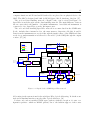
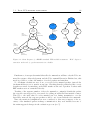
An example of a routed SpaceWire data-handling network is displayed in Figure 2.3.
The figure only shows the data-handling portion of the on-board network, the mission
critical network between the on-board computer and the AOCS is not shown. Another
usage of SpaceWire in on-board networks include direct links between high data rate
instruments (such as optical sensors) and down link radios.
Two types of addressing are defined: path addressing and logical addressing. For path
addressing, the address field of each packet has a list of all physical ports the packet is to
pass through on its way to its destination. Logical addresses are predetermined network
(or sub-network) unique addresses, each corresponding to a node.
Routing is achieved by routers examining the first character (the address field) of each
incoming packet and determining the destination and if path of logical addressing is to be
used. Each port on the router has a physical address, with a port number between 1 and
31. If path addressing is used the router outputs the packet on the physical port specified
in the packet and strips the first character from the packet – so that when the modified
packet arrives at the next destination, the first character will be the next physical port
in the path addressing. When such a packet arrives at its destination, the first character
will be the start of the message. [1]
8
Chapter 2 – Background
On-board
Computer
DPU
Instrument 1
S-Band
Radio
Instrument 2
SpaceWire
Router
SpaceWire
Router
Instrument 3
X-Band
Radio
Instrument 4
Mass Memory
Figure 2.3: Example routed SpaceWire data-handling network. All shown links between nodes
are SpaceWire links. Redundant links are not shown.
In the case of logical addressing (values 32 to 254 in the first character), the router
performs a lookup in its internal pre-configured routing table. The routing table is a
list of mappings between logical addresses and physical output ports on the router. For
logical addressing the first character is not stripped (as the procedure is repeated at the
next node the packet arrives at).
The address value 0 is reserved for the internal configuration port in the router, where
e.g. the routing tables and which links are to be activated can be configured from another
node. The value 255 is reserved for future use.
As mentioned in the previous chapter, if the protocol ID standard ECSS-E-ST-50-51C
is used, the first character of each packet should be the logical address of the destination
node. This field should be present regardless of any physical path addressing being used
or not. This gives an extra security for the receiving node, incoming packets can be
filtered if there was an error in the logical addressing. The protocol ID field of the packet
can also be filtered in this way. E.g. a node can have different handlers for RMAP and
CCSDS. With the protocol ID, the packets can be switched into their respective protocol
handler by only examining one byte value.
SpaceWire routers utilize wormhole routing, which implies that there is no buffering
of packets in the routers. As soon as the beginning of a packet is received, the router will
look at the first character of the packet and determine the correct physical output port
2.1. SpaceWire
9
to relay the packet to. If the wanted route is available to use, the router pipes out the
packet while it is being received - not waiting for an end of packet marker (EOP/EEP).
If the router stops receiving the packet before an EOP or EEP is received, it adds an
EEP after the last received data character and frees the link.
If an incoming packet is destined for an output port which is already in use, the packet
will be blocked. [1]
Ensuring that blocking on the network does not occur is up to the network application
designer. Different methods of flow control can be utilized to minimize blocking, such
as: communication initiated by a single master; scheduling of allowed transmission time
slots for nodes; transaction tracking in higher level protocols; etc. The main engineering
task is to ensure that no packets are lost due to blocking, while still utilizing the network
to its maximum capacity, as well as confining to all mission requirements and keeping
the total number of routers and nodes as small as possible.
It is also possible to use group adaptive routing in SpaceWire routers. Two or more
physical ports are configured as a group of output ports for a single logical address. When
a packet with the designated address is to be routed, the router selects a port from the
group. If the port is busy, the router selects the next port in the group. This can be
used to share the resources of multiple links and reduce blocking. [1]
2.1.7
Future Standards
There are standards currently under development that complement and extends upon
SpaceWire’s functionalities.
SpaceWire Deterministic (or SpaceWire-D) is a method which addresses the issue of
blocking in SpaceWire routers/links by defining transaction schedules which explicitly
states when a node is allowed to initiate a transaction. [9]
SpaceWire Plug-N-Play (or SpaceWire-PnP) is an extension to SpaceWire, which standardizes how SpaceWire-equipment should be identified and configured when connected
to a generic SpaceWire network. [10]
SpaceFibre is the next generation on-board data-handling network standard. It is
currently under development by the University of Dundee for ESA. It defines a very
high-speed serial interface for use with fibre-optic and electrical cables - with data rates
up to 2 Gbit/s. With multi-laning, the data rate can be increased to up to 20Gbit/s.
Compared to SpaceWire, it also reduces the cable mass and provides galvanic isolation.
[11]
One of the main differences between SpaceWire and SpaceFibre is the use of virtual
channels. Each physical SpaceFibre link is split into multiple virtual links. Communication between nodes are only allowed if there exists a virtual link between the nodes.
SpaceFibre routers are used to interconnect virtual links between nodes. SpaceWireto-SpaceFibre interfacing hardware has also been suggested, which connects multiple
SpaceWire interfaces to a SpaceFibre link. In such interfacing equipment, each SpaceWire
10
Chapter 2 – Background
link is connected to a virtual link on the SpaceFibre interface. SpaceFibre keeps with
the SpaceWire packet format, enabling connection between the two link types. [11]
2.2
Used Packet formats
This chapter describes the relevant packet protocols used in this thesis.
The simulations described in this thesis utilize packets structures as described in the
ECSS PUS standard. Due to the primary headers of PUS packets being heritage from
the CCSDS packet transfer protocol, the related CCSDS standards are also described in
this chapter.
As mentioned in the previous section, the standard ECSS-E-ST-50-53C “SpaceWire CCSDS packet transfer protocol”, which describes how CCSDS packets should be encapsulated in SpaceWire packets (using the protocol identification method described in
ECSS-E-ST-50-51C) was also used, but is not described separately in this section.
2.2.1
CCSDS packet transfer protocol
The CCSDS has published a number of recommendation standards for on-board data
handling and packetization for space systems. Two CCSDS standards regarding packetization are referenced from the ECSS PUS standard: the standard CCSDS 102.0-B-5
defines data structures for telemetry packets and CCSDS 203.0-B-2 defines structures for
telecommands packets.
It should be noted that CCSDS 102.0.B-5 and CCSDS 203.0-B-2 are no longer actively
maintained by CCSDS and are only available for historical purposes (so called “Silver
Books”). The packetization definitions mentioned here can be found in CCSDS 133.0-B-1
“Space Packet Protocol” (last updated September 2012). [12]
The CCSDS telemetry standard defines a baseline concept for packet telemetry for
spacecraft-to-ground data communication, as well as the intermediate communication
steps through the data acquisition network. The standard allows for multiple application
processes to generate source packets. The packets can be sent over a network - including
multiplexed space-to-ground links - to be delivered to one or more sink processes. [13]
The CCSDS telecommand standard defines the system architecture of spacecraft telecommanding systems. It provides a layered concept for the generation of telecommands, their
transfer and how they should be managed. It also provides a definition on how telecommand packets should be structured, including how Packet Primary Headers should be
structured. [14]
Each packet includes a mandatory Packet Primary Header, an optional secondary
header and a mandatory Packed Data Field. Figure 2.4 shows the format for a Packet
Primary Header.
The Packet Primary Header is divided in three fields: Packet Identification (or Packet
ID); Packet Sequence Control and Packet Data Length. Each of these fields are 16 bits
2.2. Used Packet formats
11
Packet ID
Version
Number
(=0)
3 bits
Packet Sequence Control
Type
Data
Field
Header
Flag
Application
Process
ID
Sequence
Flags
Sequence
Count
1 bit
1 bit
11 bits
2 bits
14 bits
16 bits
16 bits
Packet Length
16 bits
Figure 2.4: CCSDS Packet Primary Header, as outlined in CCSDS 102.0-B-5. [13]
in length. (Note that the version number field is not defined as being part of the Packet
ID field in CCSDS 102.0-B-5, it is however depicted so here to align with the ECSS PUS
standard, to avoid any confusing when mixing the standards.)
The Packet ID consists of four fields.
• Version Number, a 3 bit constant value of 0b000. It is included for the possiblity
of including other data structures in the future.
• Type Indicator, 1 bit indicating whether the packet is a telemetry source packet
(set to 0) or a telecommand (set to 1).
• Packet secondary header flag, a 1 bit flag indicating whether a secondary header is
present in the packet.
• Application Process Identifier (or APID), a 11 bit variable specifying the missionspecific ID of the application which generated the source packet.
The Packet Sequence Control contains two fields: Sequence Flags (2 bits) and Source
Sequence Count (14 bits). The Sequence Flags depicts whether the packet is the first
packet in a group, a continuing packet in a group, the last packet in a group or not
belonging to a group (also called a stand-alone packet). The Sequence Count contains
the packet’s sequential count, as counted by each APID generating source packets. This
provides a time-order of the generation packets when received and allows for detection
of dropped packets.
The final two octets of the Primary Header is the Packet Data Length, i.e. the number
of octets of data contained in the Data Field minus 1. This gives a maximum packet
data length of 65536 (i.e. without the Packet Primary Header).
12
Chapter 2 – Background
2.2.2
Packet Utilization Standard (PUS)
The Packet Utilization Standard (PUS) is defined in the ECSS standard ECSS-E-7041A “Space engineering - Ground systems and operations - Telemetry and telecommand
packet utilization”. PUS roughly covers the application layer of the OSI model. The
standard “addresses the utilization of telecommand packets and telemetry source packets
for the purposes of remote monitoring and control of subsystems and payloads”. [15]
The standard defines how CCSDS Space Packets should be utilized and defines an
application layer in the form of an on-board service concept. The standard does not address mission-specific payload data, but instead provides a framework where the necessary
packets can be defined. PUS also defines a number of standard services for spacecraft
monitoring and control. For a mission making use of PUS, not all concepts defined in
the standard have to be implemented. Instead a tailoring of the standard is made, from
the missions operational requirements.
PUS keeps with the CCSDS concept of separating packets in telemetry and telecommands and defines how these should be used for PUS packets. All PUS packets use the
CCSDS Packet Primary Header, as described in the previous chapter. The standard also
defines a secondary Data Field Header, which directly follows the Primary Header. The
PUS Data Field Header replaces the optional standard CCSDS Secondary Header. The
Data Field Header shall be used for all packets, except CPDU (command pulses, PUS
service 2) telecommand packets and spacecraft time source telemetry packets.
The PUS Data Field Header differs for telecommands and for telemetry packets. The
two respective headers are shown in Figure 2.5 and Figure 2.6.
Acknowledgements
CCSDS
Secondary
Header
Flag
(=1)
TC Packet
PUS Version
Number
(=1)
1 bit
3 bits
Ack.
Exec.
Completion
Ack.
Exec.
Progress
Ack.
Exec.
Start
Ack.
Acceptance
1 bit
1 bit
1 bit
1 bit
Service
Type
Service
Subtype
Source ID
(Optional)
Spare
(Opt.)
(=0)
8 bits
8 bits
n bits
n bits
4 bits
24 bits
n bits
Figure 2.5: PUS Data Field Header for a telecommand packet, as outlined in ECSS-E-70-41A.
For a PUS telecommand (TC) packet the Data Field Header contains five mandatory
fields:
2.2. Used Packet formats
13
• CCSDS Secondary Header Flag, a 1 bit flag always set to 0 to indicate that the
PUS data field header is a “non-CCSDS defined secondary header”. [15]
• TC Packet PUS Version Number, a 3 bit enumerated variable set to 1. This field
is included to differentiate future packet formats.
• Acknowledgement flags, four 1 bit fields, indicating what the telecommand recipient
should send acknowledgement packets for, when the TC has been received.
– Acknowledge Execution Completion Flag - determines if a response packet
should be sent when the execution of the telecommand has been finished.
– Acknowledge Execution Progress Flag - determines if response packets should
be sent reporting on the progress of the executing of the TC.
– Acknowledge Execution Start Flag - determines if a response packet should
be sent when the TC has been started.
– Acknowledge Acceptance Flag - determines if a response packet should be sent
when the TC has been received and verified.
• Service Type, an 8 bit enumerated variable specifying what type of service data is
contained in the data field of the packet.
• Service Subtype, an 8 bit enumerated variable specifying the subtype of the service
data of the packet.
The Data Field of a telecommand may also contain two optional fields: Source ID and
a Spare field. The Source ID field contains the mission-specific enumeration (of variable
length) identifying the source of the telecommand. This can for instance be used if
multiple ground control centers are at use. The Spare is a field of variable bit length,
containing zero value padding bits. The purpose of the spare bits is to - when needed increase the bit length of the Data Field Header to an integral multiple of the word length
of the used processor architecture (octets or longer for 16, 24, 32 or 64-bit architectures).
For a PUS telemetry (TM) packet, the Data Field Header contains five mandatory
fields. The fields are similar to that of a telecommand packet, but without the CCSDS
Secondary Header Flag and the Acknowledgement Flags. These two fields are for a TM
packet instead fixed string zero-value Spares. The PUS Version Number, Service Type
and Service Subtype fields for a TM are the same as for a TC.
The Data Field Header for a telemetry packet may also include up to four additional
optional fields.
• Packet Sub-counter, an addition to the sequence counter field (in the Packet Primary Header), containing the value of an incremental counter for each combination
of application process, service type and subtype. This may be used to gain more
information, in the case of lost packets.
14
Chapter 2 – Background
Spare
(=0)
PUS
Version
Number
(=1)
Spare
(=0)
Service
Type
Service
Subtype
Packet
Subcounter
(Optional)
Destination ID
(Optional)
Time
(Optional)
Spare
(Opt.)
(=0)
1 bit
3 bits
4 bits
8 bits
8 bits
8 bits
n bits
n bits
n bits
24 bits
n bits
Figure 2.6: PUS Data Field Header for a telemetry source packet, from ECSS-E-70-41A.
• Destination ID, a mission-specific enumeration identifying the destination of the
ID. This is the equivalent field of the Source ID field for telecommands.
• Time, on-board reference time of when the packet was generated. The format of
the time field is mission specific.
Like for a telecommand, the data header for a telemetry packet also includes a Spare field,
which ensure that the total header length in words (e.g. octets) is an integral number.
The mentioned fields “Service Type” and “Service Subtype” relate to the PUS services,
included in the standard. The PUS standard services are a set of commonly used onboard data handling features, such as telecommand verification and forwarding, command
distribution, housekeeping and event reporting and handling, operations scheduling and
monitoring, etc.
In each service definition a number of subservices are defined. Each subservice definition
includes a service function description and a service data packet format.
For each service a minimum capability set is included, it defines a list of subservice
requirement which are needed by a node implementing the service in question. A list of
which of the additional service capabilities that are to be implemented is provided in the
mission documentation, for the target mission.
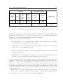
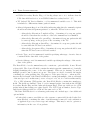
Table 2.1 displays a list of the PUS standard services and notes on which need to be
implemented by a user.
A list of allocated values for mission specific non-standard services is also provided by
the standard. These can be used on a mission-wide basis or be allocated for implementation to individual spacecraft customers.
An important and commonly used service is PUS Service 1 - Telecommand Verification
Service. As mentioned, PUS telecommand packets includes a group of flags specifying if
and when the telecommand should be acknowledged by the receiving node using response
packets. The structure of these acknowledging packets are provided by the Telecommand
Verification Service. Each of the acknowledgement flags have a number of responses,
2.3. SpaceWire hardware equipment
15
Table 2.1: PUS standard services as defined in ECSS-E-70-41A. [15]
Service Type
1
2
3
4
5
6
Service Name
Telecommand verification service
Device command distribution service
Housekeeping and diagnostic data reporting service
Parameter statistics reporting service
Event reporting service
Memory management service
8
9
Function management service
Time management service
11
12
13
14
15
On-board operations scheduling service
On-board monitoring service
Large data transfer service
Packet forwarding control service
On-board storage and retrieval service
17
18
19
Test service
On-board operations procedure service
Event-action service
depending on if the respective verification or execution step was successful or failed.
Since PUS only defines the overall packet and service field structures and not the
physical formats to be used for the fields - some mission-specific tailoring is needed. The
tailoring process takes place during the design phase of a mission. During the tailoring
process the physical formats for parameter fields can be defined per mission, application
process, service instance, request or report. [15]
Since there are optional parameters in the packets’ Data Field Headers, if they should
be included or not needs to be defined. The tailoring also includes deciding which of
the standard services and their subservices and additional non-standard services and
subservices need to be identified and defined. These mission specific standards are allowed
with service types values of 128 to 255. The PUS implementation in available spacecraft
platform equipment may be a driving factor when tailoring PUS for a mission. [16]
The PUS standard is at the time of writing, due to be re-issued by ECSS (it is currently
named using the old designation standard). [17]
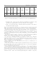
2.3
SpaceWire hardware equipment
STAR-Dundee Ltd. is a British registered company, which supplies SpaceWire equipment, including equipment for SpaceWire evaluation and testing, SpaceWire PC interfaces, routers, debugging and analysis tools, software development, etc. Because of the
16
Chapter 2 – Background
close connections between STAR-Dundee Ltd. and University of Dundee, it was opted
to use equipment from the company. Following is a description of the equipment used
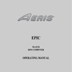
for the analysis in this thesis. The used equipment can be seen in Figure 2.7.
Figure 2.7: Used SpaceWire equipment. Top left: Front of a STAR-Dundee Ltd. SpaceWire
EGSE unit. Top right: Front of a STAR-Dundee Ltd. SpaceWire Link Analyser Mk2 unit.
Middle: Front of a STAR-Dundee Ltd. SpaceWire Router Mk2s unit. Bottom left: Top view of
a STAR-Dundee Ltd. SpaceWire USB-Brick Mk2 unit. Bottom Right: SpaceWire Lab Cable.
Source: STAR-Dundee Ltd.
2.3. SpaceWire hardware equipment
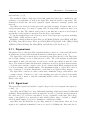
2.3.1
17
SpaceWire EGSE
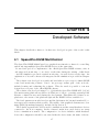
The SpaceWire Electronic Ground Support Equipment (EGSE) is a STAR-Dundee Ltd.
test device, intended for rapid development for real-time simulation of SpaceWire-enabled
units. [18]
Its main purpose is to emulate, in real-time, SpaceWire traffic from and to instruments
or other on-board equipment and can be configured to react on incoming traffic as well
as external software or electrically triggered events. Pre-defined data (such as generated
instrument data) can be stored on the device and sent as part of any SpaceWire packet.
Applications for the EGSE include simulations of on-board SpaceWire equipment such
as scientific instruments. As it is possible to use files as parts of packets, the EGSE is
also suitable for simulating instruments with high data rates. [19] [20]
It includes a specialized scripting language, which is used to describe and configure
the behavior of the emulated device by defining SpaceWire packets, schedules and state
machines. The scripting language supports sending events and status notifications to
a PC over a USB cable. It can also create events by matching incoming packets to
pre-defined formats, on link-errors, etc.
Each SpaceWire EGSE unit comes equipped with two SpaceWire ports, which are each
controlled by a separate state machine in the hardware and configured in the scripting
language. This enables the possibility to emulate two SpaceWire units in one EGSE unit.
The two state machines may share common resources, such as defined packets, matchers
and schedules. They also share the same internal memory for saved data.
The EGSE also has two trigger ports, which can be connected to external equipment.
These ports makes it possible for the EGSE to react to external events.
The USB port is used to both upload new programs to the EGSE, as well as sending
and receiving event and state information while the EGSE is running.
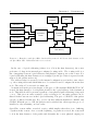
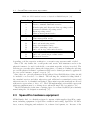
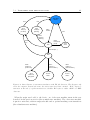
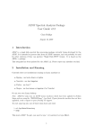
Figure 2.8 shows the EGSE hardware architecture, for one of the two state machines.
Resources such as: packets, matchers, events and schedules are shared between the two
state machines. Events can trigger a state transition in the finite state machine (FSM).
The FSM can also generate events, which can trigger state transitions in any of the
two state machines. Each state is associated with a schedule. A schedule is a table
of packets to be sent at specified times. The timing may be specified (in the scripting
language) relative to the schedules initial execution or as time deltas from the previously
sent packet.
When a packet is triggered to be sent, the packet ID is relayed to the data generator,
which adds the packet on the queue of data which is to be sent to the transmission FIFO
of the SpaceWire port associated with the state machine.
The EGSE scripting language is a language which has been specifically developed for the
EGSE, with focus on simplicity and rapid development. The syntax of the language is
designed for readability and uses the break line ASCII character (“\n”) and whitespace
indentation (“ ”) to delimit code blocks, rather than using curly braces (“{” and “}”).
18
Chapter 2 – Background
Figure 2.8: SpaceWire EGSE hardware architecture. Source: SpaceWire EGSE – User Manual
v1.05 [21]
EGSE script content is grouped in a number of different blocks, these include: hardware configuration; variable definitions; packet definitions; matcher definitions; schedule
definitions; event definitions; state machines including states. Where state blocks have
been defined within state machine blocks. All other blocks are defined outside any other
block. This makes it possible for the state machines to share content from all defined
blocks, except the state definitions - these have to be defined individually for each state
machine.
The hardware configuration defines which default data rate the SpaceWire ports should
operate at, unless explicitly defined elsewhere (overloaded).
The variable definition block contains the variable declarations. The allowed variable
types are: 8-bit and 16-bit constant integers; 8-bit and 16-bit incremental variables; 8bit and 16-bit decremental variables; 8-bit and 16-bit rotate left or right variables; 8-bit
random variables and 8-bit CRC8 variables. All of the 16-bit variables have to defined
as either big-endian or small-endian variables.
2.3.2
SpaceWire Router Mk2S
The STAR-Dundee Ltd. SpaceWire Router Mk2S is a SpaceWire router used for evaluation, developing and testing. It is equipped with eight SpaceWire ports and three
external ports: one USB 2.0 port and two parallel FIFO ports. The router also implements a configuration port with the physical address zero, as defined in the SpaceWire
standard. The front of the device is shown in Figure 2.7.
The USB interface of the router provides two channels to the SpaceWire router. These
can be used to configure the router or received data packets, as on a SpaceWire interface.
The channels can also be configured to work in interface mode, as on a SpaceWire-USB
Brick (see Chapter 2.3.3).
The device is functionally equivalent with the SpaceWire Router ASIC (AT7910E)
produced by Atmel - also called the SpW-10X Router.
Since the Mk2S edition of the router, the device is compatible with the STAR-System
2.3. SpaceWire hardware equipment
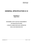
19
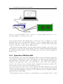
Figure 2.9: SpaceWire EGSE example configuration. Copyright STAR-Dundee Ltd., source:
SpaceWire EGSE – User Manual v1.05. [21]
device drivers and API. The USB interface of the device can be configured to be used
with the API as any other SpaceWire interface. A host computer without any other
SpaceWire interface can thereby be connected directly to the SpaceWire network the
router is connected to, using only the USB interface.
The internal switching matrix routes incoming packets depending on the value of the
first character of each received packet. Each port can be addressed using path addressing
per default. Routing settings for logical addressing can be set via the routers configuration
interface. [22]
2.3.3
SpaceWire-USB Brick Mk2
The STAR-Dundee Ltd. SpaceWire-USB Brick Mk2 provides an integrated SpaceWire
router with two SpaceWire ports and a USB interface, accessible over the STAR-System
API and drivers. The device can be seen in Figure 2.7. The USB interfaces has two
channels to the SpaceWire router, one for data and for control. The control channel is
routed to the routers port 0, so that the device configuration is always accessible. The
device has two modes: routed mode and interface mode.
In routed mode the device acts a router with two SpaceWire interfaces and a USB
interface. Packets are then routed as in any SpaceWire router, with the first character
of each packet determining the output port. The internal router is compatible with the
SpW-10X Router (AT7910E).
When interface mode is activated on a SpaceWire port, the packets will be routed
20
Chapter 2 – Background
Channel 1
Multi Channel
USB Interface
Channel 2
FIFO Port 1
FIFO Port 2
Configuration Port
1
SpaceWire Port 1
2
SpaceWire Port 2
3
SpaceWire Port 3
4
SpaceWire Port 4
5
SpaceWire Port 5
6
SpaceWire Port 6
7
SpaceWire Port 7
8
SpaceWire Port 8
9
10
11
SpaceWire
Router
12
0
Figure 2.10: Block diagram of SpaceWire Router Mk2s ports. Source: SpaceWire Router Mk2s
datasheet.
automatically from and to the data channel of the USB interface. This is useful when
the device is to be used only as a SpaceWire interface and no routing is needed. [23]
Channel 1
3
Multi Channel
USB Interface
1
SpaceWire Port 1
2
SpaceWire Port 2
SpaceWire
Router
Channel 2
4
0
Configuration Port
Figure 2.11: Block diagram of SpaceWire-USB Brick ports. Source: SpaceWire-USB Brick
datasheet.
2.3. SpaceWire hardware equipment
2.3.4
21
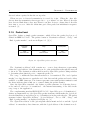
SpaceWire Link Analyser Mk2
The STAR-Dundee Ltd. SpaceWire Link Analyser Mk2 is a device used for testing and
development of SpaceWire systems. The device provides a USB interface to a host PC
and two SpaceWire ports, for input of the data to analyze. During analysis the device
is connected in series on the SpaceWire link in question. The analysis is performed with
the provided software running on the host PC.
The device shares its mechanical design with the SpaceWire EGSE, although the internal configuration differs. The front of the device is shown in Figure 2.7.
The analysis software provides the possibility to save data passing through the Link
Analyser and displays it in three views: bit; byte and packet. Timing information for
events (such as start of packets, etc.) is provided. Data from either end to the other is
saved and can be viewed in separate streams, in relation to each other. This is useful for
analysing and debugging request and response packet timing between two nodes. [24]
C HAPTER 3
Missions / Analysis
As part of the work for this thesis a mission with a SpaceWire network suitable for simulation had to be found and analyzed. The criteria for what was to be considered a
suitable mission also had to be defined.
Criteria for mission selection for simulation was defined as follows:
• Number of SpW nodes / routers – should be a substantial amount of nodes for a
sizable simulation, but not so many that implementation time would be unrealistic.
• Complexity of SpW network – should be a routed network, with the same network
routes being utilized by multiple nodes.
• Enough available information to make a meaningful simulation – e.g. data-handling
architecture; standards used; needed TM bit rate of nodes; number of modes (in
view of GS; eclipse; etc); etc.
From the selection criteria, a list of known missions utilizing SpaceWire was compiled.
Unmanned scientific satellite missions from the larger agencies were targeted. It was
also opted to pick a current mission, so that the result of the simulation would reflect
equipment and standards in contemporary use.
After review the available current missions, ESA’s BepiColombo and Solar Orbiter were
selected as the main missions to model the network simulation after.
Solar Orbiter is part of ESA’s Cosmic Vision programme. Cosmic Vision is a ESA
future mission programme, consisting of four space missions with scientific goals taking
place between 2015 and 2025. The missions are categorized using the ESA mission
classification: Large size missions (L-class), medium size missions (M-class) and small
size missions (S-class). The programme consists of a S-class mission: CHEOPS; two
M-class mission: Euclid and Solar Orbiter and one L-class mission: JUICE. [25]
23
24
Chapter 3 – Missions / Analysis
Due to the planned orbits of Solar Orbiter and BepiColombo MPO, the missions share
a lot of heritage design. This includes the use of a heat shield constantly pointing towards
the sun and covering the spacecraft, with holes for the remote sensing instruments. It
also includes the on-board data handling network and roughly the number of scientific
instruments. As the design of the OBDH network of Solar Orbiter partly being a result
of the heritage from BepiColombo – the BepiColombo on-board data handling network
was also considered.
Initially the most common use for SpaceWire in space missions was that of a point to
point high-speed serial interface, for equipment requiring higher data rates. Today multiple current and planned space missions utilize routed SpaceWire networks for their
on-board data handling and flight critical systems. The analysis here refers purely to the
on-board data handling functions for the scientific data. [1] [26]
BepiColombo is an joint ESA/JAXA space mission to be launched in August 2015. The
mission consists of a transfer module and two orbiter spacecrafts, launched together to
target orbits around Mercury. The transfer module is called the Mercury Transfer Module
(MTM) and is made by ESA. The two orbiters are the Mercury Planetary Orbiter (MPO)
built by ESA and the Mercury Magnetospheric Orbiter (MMO) - a JAXA contribution.
The OBDH network heritage from BepiColombo to Solar Orbiter refers to the network
of the MPO, the ESA segment of the mission.
Solar Orbiter is an ESA M-class mission to be launched in 2017. The spacecraft will be
placed in an elliptical heliocentric orbit, with a closest approach to the sun of about 0.28
AU. The spacecraft will examine how the Sun creates and controls the heliosphere, by
making in-situ and remote sensing measurements of the heliosphere close to the sun.
The mission hosts 9 scientific instruments, both in-situ and remote sensing. The in-situ
instruments include: EPD (Energetic Particle Detector), MAG (Magnetometer), RPW
(Radio and Plasma Waves) and SWA (Solar Wind Plasma Analyser). The remote sensing
instruments include: EUI (Extreme Ultraviolet Imager), METIS (Coronagraph), PHI
(Polarmetric and Helioseismic Imager), SoloHI (Heliospheric Imager), SPICE (Spectral
Imaging of the Coronal Environment) and STIX (X-ray Spectrometer/Telescope).
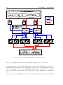
The on-board data-handling networks on BepiColombo and SolarOrbiter use routed
SpaceWire networks. There are three main sections of the network: the OBC (on-board
computer), the SSMM (Solid State Mass Memory unit) and the scientific instruments.
The interfacing towards the scientific instruments is done with three main input routers.
The input routers are each individually connected to the on-board mass memory responsible for saving the scientific data, while no connection to Earth is possible. An additional
two routers are used for communication with OBC functions and X- and Ka-band radios.
The SpaceWire routers and the mass memory is placed in one physical unit, the SSMM.
The SSMM is designed and built by ThalesAlenia Space, Milano, Italy. The on-board
25
computer functions and X-band and K-band radios are placed in one physical device: the
OBC. The OBC is designed and built by RUAG Space AB, Gothenburg, Sweden. [27]
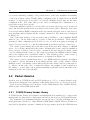
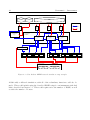
The on-board data handling network of BepiColombo can be viewed in Figure 3.1.
SpaceWire is used through-out the data-handling network. The main difference between
the two networks is the number of scientific instruments. An additional instrument is
connected to free SpaceWire port the R2 input router.
The on-board data handling SpaceWire network is accommodated in the SSMM unit.
It also includes three internal nodes: the mass memory, Supervisor Module A and B.
Data from the instruments are received through the input routers of the SSMM and data
ready for ground-transmission is delivered to the radios (of the OBC) through the output
routers. [27] [28]
X-Band TFG I/F N
K-Band TFG I/F N
LEGEND
OUT SpW Router
(NOMINAL)
SpW link
Redundant SpW link
1
2
SpW 10X
Router
R5-N
3
9
Unused SpW port
4
5
10
R5-R (Output
Cross-Strap)
Router internal Parallel I/F
Memory Read FPGA-A
("RDC FPGA-A")
R5-R
INPUT/OUTPUT
MODULE A
SUP-A Module
(Supervisor)
OBC I/F A N
OBC I/F A R
EGSE I/F A
6
7
8
2
5
SpW 10X
Router
R4-N
3
4
1
10
9
192 Gbit
Memory
Module #1
SUP
Module A
192 Gbit
Memory
Module #2
192 Gbit
Memory
Module #3
BepiC:
Free Port
R4-R
Memory Write FPGA-A
("WRC FPGA-A")
IN SpW Routers
(NOMINAL)
BepiC:
Free Port
9
8
10
1 2 3
9
7
SpW 10X
Router
R1-N
4 5
6
7
10
1 2 3
R1-R (Input
Cross-Strap)
P/L I/F: 1-N 2-N 3-N
8
SpW 10X
Router
R2-N
4 5
6
6
7
9
10
1 2 3
R2-R (Input
Cross-Strap)
P/L I/F: 4-N 5-N 6-N
8
SpW 10X
Router
R3-N
"SUP B SpW Router"
4 5
R3-R (Input
Cross-Strap)
P/L I/F: 7-N 8-N 9-N
Figure 3.1: BepiColombo SSMM SpaceWire network
All routing in the system is made through SpaceWire logical addressing. Both the nominal and redundant interfaces use the same logical addresses. [28]
Packets on-board are mainly CCSDS space packets, with the exception of router configuration packets - which are RMAP packets, due to the built-in support of the router
26
Chapter 3 – Missions / Analysis
ASICs.
Packets defined according to the PUS standard (ECSS-E-70-41A) is used to interface
with the scientific instruments over the SpaceWire network for both BepiColombo and
Solar Orbiter. [27] [28]
Except for data transfer to ground, the Solar Orbiter mission also requires communication amongst the instruments themselves. There are two types of inter-instrument
communication: real-time sharing of key measurement results between instruments and
event-specific communication which triggers specific high data rate modes in the instruments.
An example of the shared key measurements is the magnetic field vector of the MAG
instrument, with the SWA, which measures the velocities of incoming electrons.
An example of a high data rate trigger is the RPW instrument package, which will
indicate detected interplanetary shocks to the SWA and other instruments.
All inter-instrument communication uses the OBC as a central hub for collating and
disseminating the information. This is made as an analog to the Mediator pattern in
object-oriented software design. [28]
To create a simulation of the data transfered on a SpaceWire network similar to that of
the described mission networks, some implementation decisions had to be made.
It was decided to use the SpaceWire EGSE devices to simulate the traffic to and
from the scientific instruments. To minimize the total needed devices, the redundant
functions would be disregarded initially for the benefit of focusing on the nominal network
functions. Two instruments could therefore be simulated per EGSE device.
Due to the use of multiple EGSE devices and the need to simultaneous control these
- a new software for control and monitoring of multiple EGSE devices for a common
simulation was to be designed and implemented.
To verify the functions of the EGSE instrument scripts the OBC and SSMM functions would be implemented in software with CCSDS and PUS decoding and logging
capabilities. Rudimentary telecommand functions were also needed to be implemented.
Since no dedicated CCSDS and/or PUS packet API was available in house, additional
packet encoding and decoding libraries had to implemented.
To simplify the implementation of the software simulated nodes in the network, a
generic PUS-enabled network node simulation software was chosen for implementation.
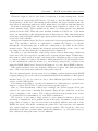
C HAPTER 4
Developed Software
This chapter details the software tools that were developed as part of the work for this
thesis.
4.1
SpaceWire EGSE MultiControl
The SpaceWire EGSE MultiControl is a graphical user interface software for controlling
and monitoring multiple SpaceWire EGSE devices at the same time.
It was developed as a complement to the official SpaceWire EGSE software, since it
only supported monitoring of one device at the time during the writing of this thesis
– and the simulation procured required monitoring of several devices at the time. An
explanation of how the software was integrated in the simulation is provided in Chapter
6.
The software was developed as a study and was built as a prototype for future EGSE
control and monitoring software. Due to its prototype status, part of the work also
included testing and evaluating the software. This also made it possible to test new
design ideas, not part of the official EGSE software.
The software was developed using C++, Qt4 and the SpaceWire EGSE API. [29] [30]
The main testing platform was Microsoft Windows 8, but no operating system-specific
libraries or functions were used during the development. This makes the software crossplatform to the extent of the platforms Qt4 and the EGSE API are available for.
The development was mostly based around the Qt framework, but used standard C++
data types and containers when possible. The styling of the graphical elements were done
using QML (Qt markup language), included in Qt version 4.
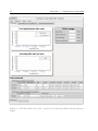
The software separates the devices used for simulation and the actual hardware devices
connected to the host computer. In the software’s main view, used devices are setup
before a simulation is started. The configuration of a device includes: which hardware
device the configuration should be associated with; the device name; the name of the two
27
28
Chapter 4 – Developed Software
cores (state machines); naming of all possible states of the state machines and naming
of the four software events. Finally which configuration file (compiled from an EGSE
script) to be used by the device has to be decided. Multiple devices may use the same
configuration file. The same dialog is also used for changing the configuration of a
previously created device profile.
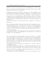
When the simulation profile for a device has been created, the device can be monitored
and controlled through the main view window and event log files. When the device has
been loaded with an EGSE configuration file, the current and active states of the device’s
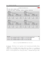
state machines will be displayed in the software’s main view. The main view is displayed
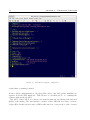
in Figure 4.1.
One of the main features of the program is the possibility to control multiple EGSE
units at once. In the main window, a panel of buttons are included. These include
starting (loading configuration) all devices at once, as well as stopping (resetting) all
devices. Devices can also be controlled individually from their respective control box.
The event log saves timing and event data about all detected state changes of a EGSE
device - for both the current and active states. All main user events - such as: simulation
device created or deleted; devices loaded or restarted and user triggered software events
- are also included in the event log. The event log is written in a human-readable format
and is also displayed in a detachable window. The default position of the event log
window is at the bottom of the main window, as displayed in Figure 4.1.
The event log can be a useful diagnostics tool for EGSE script development, as it makes
it possible to extract information about timing and the order of state changes. When
multiple events occur during a short time-span, the time deltas between events may be
too short to monitor the order of events in real-time. An example of such a situation is
the change to a state with a short packet transmission schedule and an automatic state
transition at the end of the schedule.
4.2
Packet libraries
As there were no CCSDS header and PUS packet protocol C++ software libraries available in-house during the development for this thesis, these had to be developed as well.
Both developed libraries were modeled on the STAR-Dundee Ltd. RMAP Library,
which is part of the STAR-System API.
4.2.1
CCSDS Primary Header Library
A CCSDS packet library was designed and implemented in standard C, to support the
main packet encoding and decoding features needed by the developed PUS packet library.
The standard C programming language was chosen due to it being well-supported on
many platforms, as well as to align with the STAR-Dundee RMAP Library. It therefore
uses (and is dependent on) macro definitions for type names, used in the STAR-System
4.2. Packet libraries
29
Figure 4.1: SpaceWire EGSE MultiControl main view.
API libraries. The library is also dependent on the C standard general utilities library
(“stdlib.h”).
Functions for the CCSDS Packet Primary Header (see Figure 2.4, as explained in
Chapter 2.2.1) were implemented. Also included were functions for decoding the CCSDS
header of a received packet from a void-type byte array, to a structured data type format.
30
Chapter 4 – Developed Software
In addition, the reverse functions: for creating a byte array suitable for transmitting on
a SpaceWire device, from a list of parameters were also included.
In the developed user-end software, the implemented CCSDS packet library was never
addressed directly - but always used through the PUS library. No functions for encoding/decoding any other CCSDS defined secondary headers were implemented. Neither
were any functions for directly encoding/decoding generic CCSDS space packets included.
Since the CCSDS Packet Primary Header definition includes no optional or variable
length fields, no configuration of the library is needed. Compile-time macros are however
included, to enable change of the length and positions of the fields in the header, as well
as changing the values of constant fields (such as the Packet Version Number field).
4.2.2
PUS Packet Library
The PUS packet library is based on the same form as the CCSDS packet library described
in the previous section, the main difference being that the PUS packet library consists
of functions for encoding and decoding entire packets and not just headers.
For encoding and decoding of the Packet Primary Header part of PUS packets, the
developed CCSDS packet library is used.
Similar to the implemented CCSDS packet library, the PUS library is implemented
in standard C. It is also dependent on the same libraries as the CCSDS packet library,
including the CCSDS packet library itself. Additionally the C standard string library
may be used for some functions, if available on the compilation platform.
For the packets secondary header, the Data Field Header (as defined in the PUS standard), structures and functions for encoding and decoding where implemented. The
structures and functions were split for telemetry packets and telecommand packets. This
was done due to the different fields in TM and TC, as outlined in Figures 2.6 and 2.5 in
Chapter 2.2.2.
For the packet generation, the library uses a common packet structure for both telecommands and telemetry. The packet structure includes: the Packet Primary Header (structure defined in the CCSDS library); the Data Field Header (structure defined in the PUS
library) and a generic field for the Packet Data Field.
The fields in the structures defined in the library are not intended to be accessed
directly, but rather through included data access methods.
The library also includes the non-standard division of the APID field in the CCSDS
Header, into a 7 bit process ID (PID) field and a 4 bit packet category (PCAT) field.
[26]
The PUS packet library also includes optional support for the ECSS-E-ST-50-53C
“SpaceWire - CCSDS packet transfer protocol” for decoding of incoming packets, which
defines how CCSDS packets should be encapsulated in SpaceWire packets. [8]
This was included to allow quick decoding of incoming packets directly from a SpaceWire
device, when the application using the library does not implement support for any other
4.2. Packet libraries
31
protocols. The application may then skip the intermediate step of internal routing of
packets depending on their protocol. The application still needs to verify and handle the
logical address field of the packet.
The PUS library also includes run-time configuration of some of the variable parameters of PUS packets. This includes configuration of inclusion of optional fields in the
Data Field Headers and their respective lengths (when applicable). It also includes configuration of when SpaceWire encapsulation should be considered while decoding packets,
as well as the value of the protocol ID (as specified in ECSS-E-ST-50-51C “SpaceWire Protocol identification”) for mission-specific non-standard values. Since some platforms
use (non-standardized) padding between the SpaceWire protocol ID header and the start
of the PUS headers, optional zero-value padding of variable length may also be configured
in the library. [6]
Run-time configuration was chosen instead of compile-time configuration, due to the
library’s implementation being focused on usage in applications for multiple configuration
- rather than only a mission-specific implementation.
4.2.3
PUS Standard Services Library
In conjunction with the developed packet libraries, a library containing functions for some
of the standard PUS services used in the simulation control and monitoring software was
created.
The library was not made as a complete implementation of all services in the PUS
standard, but rather focused on the service functions that were needed for the applications
used in the simulation work. This includes what subservices were implemented for each
service.
In contrast to the developed packet libraries, the service library functions do not encode
or decode entire packets. Instead the service libraries rely on the PUS packet library for
decoding the received packets and verifying that the correct format is being used. They
do however provide functions for encoding/decoding the service data in the Data Fields
of the PUS packets.
The library does not include a general process for deciding what action to take - i.e.
which service library function to decode the service data of a packet with, when receiving
an arbitrary packet. This type of process is instead expected to be included in the user
application which utilizes the libraries, to allow for scalable usage of the library. The
application will only need to include the methods for the services which are used.
In the case of the software used in this thesis, this is done by the PUS Node software
depicted in Chapter 4.3.
Most importantly for the application, the PUS Service 1 - Telecommand Verification
32
Chapter 4 – Developed Software
was implemented. The Telecommand Verification service defines 8 service subtypes.
These subservices types are grouped in pairs, with a pair for each of the 4 types of
acknowledgements included in PUS Data Field Header for telecommands - as shown in
Figure 2.5 in Chapter 2.2.2. Each pair includes a report type for success and a report
type for failure, in regards to the respective verification or execution stage of the received
telecommand.
The library implements encoding and decoding functions for the two acknowledgements used in the simulations described in this thesis: acknowledgement of telecommand
acceptance and acknowledgement of telecommand execution completed.
4.3
PUS Node
The PUS Node software was developed as a prototype monitoring software for a general
PUS enabled SpaceWire network node. The focus of the implementation was to have a
piece of software capable of decoding received PUS packets over a SpaceWire interface
and display the results in a graphical user interface (GUI). The software also needed
some rudimentary packet generation mechanisms.
The software does only deal with the packet layer of the communication and does not
consider any of the reporting data in the packets. Neither does the software simulate any
of the application layer functions above the PUS packets and services.
The prototype was to be tested as part of the on-board data handling network simulation (in conjunction with the scripts developed for the EGSE) and its usability evaluated.
The software was developed using C++11, Boost libraries, QT4 and the STAR-System
library for interfacing with STAR-Dundee Ltd. SpaceWire interface devices. The software also uses the CCSDS and PUS packet libraries developed as part of this thesis. The
software was developed and tested mainly with a GNU system running the Linux 3.2
kernel, but the software was developed to be compiled on any platform supporting the
used libraries. [31] [29]
The software is split in two major parts: the SpaceWire/PUS packet handling and the
user interface. Another important component is the simulation configuration. Figure 4.2
shows a package diagram displaying the software’s main components and dependencies.
The configuration of the PUS Node is contained in an external configuration file, which
is loaded when the software is started. The configuration files consists of: general configuration of the simulation; global configuration of the PUS libraries (please see Chapter
4.2.2) and individual configuration of each used SpaceWire hardware interface device.
An example configuration file is shown in Figure 4.3.
The PUS Node software can be configured to use multiple (up to 32) SpaceWire devices.
The “SpaceWire Device Handler” package shown in the Figure 4.2 contains a C++
class developed to bridge the STAR-System C API to the object-oriented design of the
4.3. PUS Node
33
PUS Node
SpaceWire
Device Handler
STAR-System
API
PUS Packet
Library
CCSDS Packet
Library
PUS Packet
Handling
Simulation
Config
User
Interface
PUS Service
Library
Figure 4.2: UML Package diagram of PUS Node dependencies.
software. For each handled hardware device, an instance of the class is instantiated
associated with the ID number of the device. An additional static instance of the class
handles the incoming callbacks from the API and dispatches them to the object with the
correct device ID. Outgoing calls are handled directly by each object.
The device handler was developed early on in preparation for the work of this thesis.
A C++ version of the STAR-System API has been released since then, making the implementation above partly obsolete.
The main architecture of the PUS Node software can be seen in Figure 4.4. All packets are
received or dispatched through the SpaceWire device handler. When a packet is received
the SpaceWire header is checked. The logical address field in the received packet has
to correspond with the configured address of the receiving SpaceWire address, otherwise
a warning is issued. The received packet protocol ID field in the packet is also checked
towards the ID value configured for the PUS packet library. If a packet passes the
SpaceWire packet related checks, it is then passed on to the PUS packet decoder, which
verifies the PUS structure of the received packet and dispatches it to the correct service
handler.
PUS telecommand packets may be generated through an optional widget in the user
interface. When a telecommand has been sent, the software keeps track of the requested
acknowledgements. Once the correct acknowledgements have been received, the telecommand is released. If the target node fails to respond with the correct PUS reports within
34
Chapter 4 – Developed Software
Figure 4.3: PUS Node example configuration.
a time limit, a warning is issued.
In the software implementation, the SpaceWire device and PUS packet handling are
separate from the GUI functions. This allows for a headless mode, i.e. running the
software without the Qt GUI.
The GUI of the PUS Node software was written using the Qt4 framework and used
QML for the styling. The user interface consists of three different view tabs: overview;
a SpaceWire breakdown view and a PID breakdown view. A screen shot of the overview
4.3. PUS Node
35
Figure 4.4: PUS Node simplified architecture, connection from the Telecommand Verification
Service to the packet scheduler is not shown.
tab can be seen in 4.5.
The overview tab displays (in rolling graph form) the current receiving transmission
and receiving data rates for all devices, as well as a graph containing all of the current
receiving data rates for each of the configured SpaceWire ports.
The other two views shows breakdowns of more detailed statistics for each SpaceWire
port and configured PID (all processes which the software is to communicate with during
the simulation run).
A binary log file format for the received and sent data traffic was developed, as a
prototype of a packet log format including information about status of the decoding of
the program. This was considered useful for log viewers, which could display not just
the received data - but also how the user application, responsible for handling the data,
responded to each incoming data packet.
36
Chapter 4 – Developed Software
Figure 4.5: PUS Node GUI screen shot, overview tab including the Telecommand generation
widget.
C HAPTER 5
EGSE Instrument Simulation
This section details the instrument simulation scripts made with the SpaceWire EGSE
scripting language. All in all, three different instrument simulations were created using
the EGSE scripting:
• A dual-instrument setup, with two PUS enabled instruments fitting in one EGSE
device - with one SpaceWire port used for each instrument.
• Same as above, but with extra verification steps for incoming telecommands. It
also includes extra error messages for invalid telecommands.
• A single instrument with redundant SpaceWire links, utilizing a full EGSE device.
The decision to make simulations with both one and two instruments was made to illustrate what can be fitted in a EGSE device in different configurations, depending on
what behavior is required by the unit-under-test connected to the device in a real use
case scenario. Another reason was to find which resources could be shared between two
separate simulations in one device.
5.1
Dual PUS-enabled instruments
The main EGSE setup included in the network simulation was a script simulating two
PUS enabled instruments, each utilizing one of the EGSE’s two SpaceWire links.
The total number of implemented PUS services was limited to the maximum number
of states, events and state transitions in the EGSE. Most of the packet data fields of the
PUS packets were replaced with random or zero value data.
The states were split into two categories: main states and response states. The state
diagram for one of the two instruments in an EGSE device can be seen in Figure 5.1.
Four main states were used: a startup state, a housekeeping only state and two science
transfer states.
37
38
Chapter 5 – EGSE Instrument Simulation
When the script is loaded to the device, it starts in a one-time startup state. In the
startup state an event packet (PUS Service 5) is sent, to alert the OBC that the device
has (re)started. At the end of the startup packet schedule, the device transitions into the
state where housekeeping packets are sent continuously to the OBC at a fix time interval.
From the housekeeping state, the state machine may transition to either of the two
science transfer states. These transitions are made by sending specific telecommand
packets from the OBC. When the state machine transitions between two of the main
states, an intermediate acknowledgement state is first triggered. The acknowledgement
states have packet schedules with the appropriate packet response packets and transitions
at the end of the schedule.
In the science transfer states, the device sends science data at preset interval and packet
sizes. The schedules could also be customized to emulate the behavior of a specific
instrument. Housekeeping data is still sent continuously to the OBC in the science
transfer states. The telecommand and telemetry packets handling science control and
reporting were specified using the non-standard service number 21.
In addition to the intermediate acknowledge states between main states, additional
states were added for responses to specific service requests and user input. Transitions to
these states could be made from any of the main states. Including a state for responding
to a memory dump, according to the Memory Management Service (PUS standard service
6). Also including an event report state (e.g. an anomaly), triggered by a software event
using the EGSE MultiControl described in Chapter 4.1 (or the official EGSE software).
Time packet matchers were also included, which were bound to the acknowledgement
state of the active main state (when the time packet arrived).
The telecommand packet detection was done by defining a packet matcher (in the EGSE
scripting language) for each of the telecommands included in the simulation. Each packet
matcher had to be once for each node, due to their different SpaceWire logical address
and process ID (PID) fields.
For telemetry responding to specific telecommands, two different types of packets were
defined: a generic PUS Service 1 packet and service specific packets.
Since no 14-bit incremental counters were available, the Packet Sequence Field was
replaced by a preset byte containing the Sequence Flags and zero-value bits, as well as
a byte containing a 8-bit counter. The counter would then wrap (restart at zero) after
255 packets had been transmitted, for each APID combination.
The decision of only using a single generic for telecommand verification (service 1)
was made to simplify the mode transitions and reduce the total number of states in the
script. Since no saving of data of received data was available with the used version of the
EGSE, the service data fields containing the packet ID of the respective telecommand
were replaced with zero value bits in the response packets. The exception to this were
fields that would have constant values during the simulation, e.g. the packet category
field, which was always the same for telecommands.
5.1. Dual PUS-enabled instruments
39
RESTART
ANY STATE
Send
PUS(5,X)
[Event-Start]
Match
PUS(6,5)
[Memory]
SWEvent0
ANY MAIN
STATE
EoS
Send
PUS(3,25)
[HK] repeat.
Match
PUS(21,1)
[Science Rate 1]
EoS
Match
PUS(9,129)
[Time]
Match
PUS(21,1)
[Science Rate 2]
PREVIOUS
STATE’S
ACK STATE
Send
ACKs
Match
PUS(21,2)
[Science off]
EoS
Send
ACKs
Send
ACKs
Match
PUS(21,2)
[Science off]
Send
PUS(5,X)
[Event-X]
Send
PUS(6,6)
[Memory]
End of
Schedule
End of
Schedule
PREVIOUS
STATE
EoS
Science
Rate 1
Science
Rate 2
Match
PUS(21,1)
[Science Rate 2]
Match
PUS(21,1)
[Science Rate 1]
Figure 5.1: State diagram of a EGSE simulated PUS-enabled instrument. “EoS” depicts a
transition at the end of a packet transmission schedule.
Furthermore, it was predetermined that all telecommands would have only the Telecommand Acceptance Acknowledgement and the Telecommand Execution Finished set, this
made it possible to reduce the number of needed packets and matchers.
No checksum calculations were done on received telecommand packets, instead the
checksum fields were set to match on any byte. Checking that the packets had the correct
lengths were made by matching on the EOP marker at the end of packets. Packets with
EEP markers were not matched directly.
Tracking of the sequence number of the telecommands, to uniquely identify the packet
the response was triggered by, were made by adding an additional incremental counter.
This led to the issue that if a telecommand was lost during transmission over the
SpaceWire network, the response packets would be out of sync with the telecommands.
Since the mentioned simplifications were considered to have major impact of the accuracy of the simulated packet exchange communication, they were included as some of
the main suggested changes in the evaluation process (see 7).
40
5.2
Chapter 5 – EGSE Instrument Simulation
PUS enabled instrument with TC fail detection
Since the standard PUS Service 1 (Telecommand Verification) is one of the most important ones for communicating with any PUS node - an extra script was made with
additional features focusing on extending the functionalities of that service.
The main focus was to include detection of errors in received telecommands. The
secondary focus was to allow for more telecommand packets to be matched, circumventing
the EGSE’s limitation of maximum of five transitions per state. [21]
This was made possible by breaking down the packet matching steps. In the previous simulation, each packet was matched by an individually defined packet matcher in
the EGSE script. The altered approached was based on matching parts of incoming
telecommand packets in multiple steps.
Figure 5.2 shows the state diagram of the packet matching states. The main states
were the same as for the instrument simulation shown in Figure 5.1.
When a packet is received while the state machine is in one of the main states, a header
section of the packet is first matched. This matcher ensures that the received packet was
addressed to the correct SpaceWire logical address and process ID (PID). It also ensures
that the main structure of the header CCSDS/PUS up until the service type field is
correct.
In a second step either the rest of the received packet is matched or only the service
type. The latter was used for services with multiple implemented service subtypes. In the
case that no correct match was made before the end of the packet was received (i.e. an
EOP or EOP character was matched), a report according to TC Verification subservice
2 - Telecommand Acceptance Error Report was sent.
If a service type with multiple service subtypes was matched, a third step was used.
This step matched either the rest of the packet (starting at the subservice field) or no
correct match, as described above.
5.3
Instrument with redundant links
Finally a script using all of the previously mentioned functions, as well as emulating the
SpaceWire hardware redundancy requirements (put on a typical scientific instrument for
a space mission) was developed.
This type of EGSE script was also useful for evaluating new functions needed for covering hardware requirements, outside of the service requirements generating SpaceWire
traffic to and from the simulated device (see Chapter 7).
Since this setup required both of the device’s two SpaceWire ports, only one instrument
was simulated per device. This enabled sharing of some of the EGSE’s internal resources
between the two state machines.
Since packets are defined independent of which state machine they are to be used for,
the sequential packet counters could be shared between the two state machines.
5.3. Instrument with redundant links
41
ANY MAIN
STATE
EoS
EoS
Send
PUS(1,2)
[TC-Error]
Send
PUS(6,6)
[Memory]
Match
Header
EoS
Match
PUS(6,5)
[Memory]
Match
E-P
Wait
Match
PUS(9,129)
[Time]
Send
ACKs
Match PUS(21,...)
Wait
Match
PUS(21,2)
[Science off]
Send
PUS(3,25)
[HK] repeat.
Match
PUS(21,1)
[Science Rate 1]
Science
Rate 1
Match
PUS(21,1)
[Science Rate 2]
Science
Rate 2
Figure 5.2: State diagram of instrument simulation with TC fail detection. The diagram only
shows the stepwise transitional states, the main states have been omitted. “EoS” depicts a
transition at the end of a packet transmission schedule. E-P refers to either a EOP or a EEP
character.
When the script was loaded to the device, one of the state machine starts in the way
described in the previous section (the nominal state machine). The other state machine
is put in a wait state, with an empty schedule and no packet matching event transitions
(the redundant state machine).
42
Chapter 5 – EGSE Instrument Simulation
The nominal state and the redundant state machines works essentially the same, with
the main difference being the starting trigger. The nominal state machine includes a
state transition that was triggered by a hardware link error event on the nominal link.
In the case of such an event, the nominal state machine was put in a wait state and the
redundant state machine was started.
When the redundant state machine was started, an event packet reporting on the switch
was sent.
Included was also a user-triggered event, which emulated a link error and switched the
state machines in the same way as described above.
Alternatively a telecommand for starting the redundant link could be defined, to prohibit the redundant SpaceWire interface to immediately start sending data - but instead
wait for the OBC to detect the error and command the redundant SpaceWire router to
start.
C HAPTER 6
Simulation
This chapter details the SpaceWire network simulation that were made with the described
hardware equipment and software tools.
6.1
Systems demonstration simulation
During the evaluation work for this thesis a simulation was setup, as a system demonstration of the developed software and EGSE scripts. The simulation was largely based
on the analyzed on-board networks described in Chapter 3.
The simulation was scaled down from the analyzed missions to include eight simulated
instruments in total. The input SpaceWire routers (which are the main interfaces towards
the instruments) were scaled down from three to two. The cross-strapping SpaceWire
links between the routers were set to two links, keeping with the total number of nominal
cross-strapping links. From the perspective of the links going out from the routers, this
replaced one of the intermediate routers with a direct SpaceWire link. None of the redundant network functions were included. The main hardware and software components
of the simulation can be seen in Figure 6.1.
Since the internal FIFO ports of the routers could not be used to interface with a
host computer, the USB interface of the router together with a SpaceWire-USB Brick
were used instead (connected to port 5, which was free due to redundant links not being
included). The SpaceWire-USB Bricks were all set to work in interface mode (as described
in Chapter 2.3.3).
Another Brick was used as a simplified connection to the on-board computer (OBC)
functions. The mass memory supervisor module (SUP-A) (and its router), as well as the
outgoing routers were not included. The reason for this was to focus the simulation on
the data generation and acquisition on the network between the scientific instruments
and the platform functions.
Not shown in the simulation network figure was a SpaceWire Link Analyser, which was
43
44
Chapter 6 – Simulation
Figure 6.1: Demonstration OBDH network simulation setup.
used to debug links during the development and configuration of the network.
For the simulation of the scientific instruments four SpaceWire EGSE devices were used.
The EGSE script which was used during the testing was the dual-instrument setup described in Chapter 5.1. The extended EGSE scripts described in Chapters 5.2 and 5.3
were also included and tested (to some degree) in alternate configuration of the simulation.
For the control of the EGSE devices a host PC running the developed SpaceWire EGSE
6.1. Systems demonstration simulation
45
MultiControl software (see Chapter 4.1) was used. Each EGSE was loaded with a variation of the baseline script, with variables such as SpaceWire address, used process IDs
(PIDs) and data generation rates customized.
Two instances of the developed PUS Node software were used. These simulated some of
the SSMM and OBC functions. The first was configured to act as the input ports and
the Write Module of the SSMM. This included configuring the four SpaceWire interfaces
in two groups, one for each input router. The first PUS Node instance included the
possibility to send telecommands, but this feature was disabled as it was not of interest.
The OBC functions were simulated in another instance of the PUS Node software. In
this instance, the telecommand generation widget was enabled and customised for the
simulation need.
The router configuration was made through the Device Configuration tool included in
STAR-System.
The housekeeping and scientific data transfer data rates from the instruments were set to
emulate expected data rates for a deep-space mission, like the ones described in Chapter
3. The housekeeping data was set to always be on, from as soon as the EGSE were
started. The scientific data generation was set to two different rates per instruments or
completely off. Telecommands from the OBC simulator determined what data rates were
to be used at what times.
The housekeeping data as well as event reports was routed directly to the OBC. and
all scientific data, directly to the SSMM simulator. Telecommand could be routed from
the OBC to any of the instruments.
The router configuration used in the simulation can be seen in Table 6.1. The SSMM
was addressed using one logical address per node it would be receiving from, using the
logical address values 32-39. This was done to emulate the behavior of the SSMM device
described in Chapter 3. The address range was chosen as it starts on the lowest value
allowed for SpaceWire logical address (lower addresses are used for path addressing).
Each instrument was given a unique SpaceWire logical address, with a value between 64
and 71 and the OBC was given 128.
The simulation made use of the split of the APID field into a PID (process ID) and
PCAT (packet category).
Each instrument was given two PID: one for control and monitoring and one for science
data. The control and monitoring PID was responsible for all housekeeping data, event
reports and receiving telecommands. The second PID was used for all science data
generation. This was done to emulate an instrument which separates its control function
from its detectors - as described in Chapter 5.
An alternative setup where multiple PIDs for science data per instrument was also
46
Chapter 6 – Simulation
Table 6.1: SpaceWire logical address to physical port number routing configuration used in the
systems demonstration.
Function
Address
SSMM
Instrument
Instrument
Instrument
Instrument
Instrument
Instrument
Instrument
Instrument
OBC
1
2
3
4
5
6
7
8
Router R1-N
Router R2-N
32
33
34
35
36
37
38
39
5,
5,
5,
5,
6,
6,
6,
6,
9
9
9
9
7
7
7
7
6,
6,
6,
6,
5,
5,
5,
5,
7
7
7
7
9
9
9
9
64
65
66
67
68
69
70
71
1
2
3
4
6,
6,
6,
6,
7
7
7
7
7
7
7
7
6,
6,
6,
6,
1
2
3
4
128
8
6, 7
tested, to emulate an instrument package with multiple detectors.
The packet category field was used to further separate packet types. PCATs for housekeeping, events, science data and telecommands were defined.
The PUS Node software, which was simulating the OBC and SSMM write module
functions, was configured to separate the packet statistics depending on the instruments
PID values. The PID values in received packets were also cross-checked with a list of
allowed values for each SpaceWire port. If there was a mismatch in the received PID
and sending node for a packet, a warning was issued in the log file.
The mentioned setup was built up with hardware equipment and demonstrated for the
staff of the University of Dundee Space Technology Centre and STAR-Dundee Ltd. A
photography of the simulation setup can be seen in Figure 6.2.
6.2
Mission data-handling simulation
The SpaceWire networks for the space missions discussed in Chapter 3 were modeled with
SpaceWire development and evaluation equipment, as a scaled up version of the systems
demonstration described in the previous section. A simulation could be set up to, in
6.2. Mission data-handling simulation
47
Figure 6.2: Photo of simulation setup, during system demonstration at the STAR-House,
Dundee, August 2013.
real-time, emulate the data transfered over the SpaceWire network for one or multiple
mission modes.
During the simulation an event with high scientific interest, the OBC could command
all of the relevant instruments to increase their data rates. The event could be started
by a user-triggered event from one of the EGSE-based instruments, sending a packet to
the OBC with an event report.
As the SSMM write module would only be receiving data from the instruments, the
extra latency in using the software described would not effect the simulation. The same
is true for the OBC functions which could be triggered at any time by a user. The extra
delay from the user triggering the event to the packet being sent, should not affect how
a receiving node reacts.
An additional router would have to be added for the Mass Memory Supervisor Module
functions. This could be done using either a SpW-10X Router (such as the SpaceWire
Router Mk2S used for the Input Routers) or alternatively with a SpaceWire-USB Brick
in router mode - if only one of the two FIFO ports connected to the SUP Module is
needed. If both FIFO ports were to be used, an additional SpaceWire interface would be
needed.
The simulated instruments would also have to be customized to fit the main data generation corresponding to the different detectors of the instrument packages.
48
Chapter 6 – Simulation
SSMM Simulation PC
OBC Simulator
SUP-A Simulator
SSMM Write Module Simulator
LEGEND
SpWUSB
Brick
SpWUSB
Brick
SpWUSB
Brick
SpWUSB
Brick
SpaceWire link
USB cable
2
SpW-USB Brick
4
R4-N
IN SpW Routers
(NOMINAL)
1
5
8
10
5
SpW Router Mk2S
R1-N
1
2
7
6
3
7
10
1
2
3
5
6
SpW Router Mk2S
R2-N
6
7
8
10
SpW Router Mk2S
R3-N
1
2
3
Link Analyser
1
RPW
EGSE-1
2
EPD
1
MAG
2
1
SWA
EGSE-2
PHI
2
1
EUI
STIX
EGSE-3
2
METIS
EGSE-4
1
SPICE
EGSE-5
Simulation Control PC
Link Analyser
EGSE Sim. Control
Figure 6.3: Solar Orbiter OBDH network simulation setup example.
Additionally a full-scale simulation, with all of the redundancy functions could also be
made. This would include using the described EGSE script for an instrument with dual
links, described in Chapter 5.3. This would require twice the number of EGSE, as well
as twice the number of routers.
2
SoloHI
C HAPTER 7
Results
This chapter present an discussion of the results from the development of the simulation
software tools and EGSE scripts used in the simulation section.
7.1
SpaceWire EGSE evaluation
As part of this thesis an evaluation of the SpaceWire EGSE device was carried out. The
purpose was to evaluate the EGSE for implementing a realistic simulation of a typical
modern scientific space instrument using SpaceWire. Since the selected mission was
using CCSDS space packet standards and PUS, focus was put to find features needed to
increase the support for these protocol standards.
During the development of the simulations other possibly useful improvements were
also found, these have also been included in this section. It should be noted that the
EGSE instrument simulation described in Chapter 5 intentionally tried to find the current limitations of the SpaceWire EGSE device with generic implementations of control
and reporting functions. Other implementations could be made, which uses the already
existing functions of the device to circumvent some of the discussed limitations.
The evaluation work led to an internal report being issued to University of Dundee and
STAR-Dundee Ltd., highlighting suggested changes and added features for improving the
CCSDS and PUS support of the EGSE device. These suggested features were graded by
their respective impact if they were to be implemented. [32]
The following section includes the information from the report, rewritten to suit the
format of this thesis. Some of the detailed information from the report has been omitted
to save space.
Some features which were discussed and have already been included in the EGSE
software and API. These include:
• Removal of the maximum number of 16 constant variables per script.
49
50
Chapter 7 – Results
• Possible to refer to constant variables in packet matchers. This reduces the use of
hard coded values in packet matchers.
• Color highlighting in the SpaceWire EGSE script editor - a color profile for the
.egse format for the popular editor Vim was also created.
7.1.1
CCSDS support
The EGSE currently has 8 bit and 16 bit incremental counters. To emulate the needed
behavior of the Sequence Counter field in CCSDS Packet Primary Header, a 14 bit
incremental counter is needed. The workaround employed in the simulations described
in this thesis includes using a padding byte (with the two most significant bits set to the
Sequence Flags) and 8 bit incremental counter. This however only allows sequence count
to have values up to 255 and will generate errors in any connect equipment (under test).
The severity of this error is considered to be high.
The solution is to add either an incremental counter specifically for the CCSDS protocol, i.e. “inc ccsds(0b11, 3)” would set the two sequence flags to 1:s and start the 14-bit
incremental counter with the value set to 3.
Alternatively adding maximum and minimum value to the already existing 16 bit counters, i.e. “inc16be(0, 0xC000, 0xFFFF)” would set the starting value to 0, the minimum
value to 0xC000 (sets to two MSB to 0b11) and 0xFFFF is the maximum value (where
the counter wraps). This would allow for a generic support for any protocol which uses
counters with lengths that are not multiplies of 8 bits.
7.1.2
PUS support
Currently the EGSE only includes the RMAP 8 bit checksum and no 16 bit checksums.
PUS recommends either 16 bit Cyclic Redundancy Check (CRC) or 16 bit ISO standard
checksum.
New variables for these two types of checksum could be added to the EGSE, i.e.
“crc16()” would work the same way as “crc08()”. Alternative checksum types could
be implemented and defined as a parameter to the variable above.
As this feature affects (at least) all PUS telecommand packets, its severity was set to
high.
Currently no checksum calculation can be made in matchers for incoming packets. This
disables the possibility to detect bit flips in e.g. telecommands, which could result in the
wrong command being executed. It is suggested that checksum calculations to packet
matchers are added, on the same form as the checksum calculation for packets. I.e.
“start(CRC)” would start the checksum calculation (where “CRC” is a checksum variable) and “stop(CRC)” would stop it. If any wild card matchers (e.g. “0x–”) are used
as part of the matcher, the calculation should use the corresponding field value of the
7.1. SpaceWire EGSE evaluation
51
received packet.
Additionally an extra field could be added to the matcher events which specifies if the
matcher should trigger an event when the checksum calculation was successful or not.
It was found that some PUS telecommands exceeded the total number of elements in
an EGSE packet matcher (currently set to 24 elements). It is suggested that limit is
increased to at least 32 elements.
Optionally a match multiplier, similar to byte multipliers work in EGSE packet definitions, could be added. I.e. “0x– * 250” would match on 250 bytes with any values and
still allow to match the end of packet marker.
It was found that only partial implementation of the PUS service 1 could be made (see
Chapter 5), since it is currently not possible to copy values from incoming packets and
reuse them in outgoing packets. It is suggested that saving of incoming values to variables
is added, e.g. “0x– = myVar” in a matcher would match on any byte value and save it
in “myVar”. The variable could then be used as normal in outgoing packets.
It should be noted that this feature has already been identified as a future improvement, to better support the RMAP protocol. [20]
The current limit of five event transitions from a state limits the number of telecommands
a state machine can respond correctly to. It is suggested that this limit is increased to
allow at least 10 event transitions.
Optionally an implementation similar to the time-code guards could be used, but using
the value of a field in the incoming packet to determine which schedule to execute. This
can be combined with the functionality to save values to variables in packet matchers
mentioned above. I.e. “0b00001001 : do sch ackBoth” - where the variable contains the
acknowledgement fields of a PUS telecommand - would trigger a schedule where both
acknowledgement of telecommand acceptance and telecommand executed is sent. Other
guards could trigger schedules with other acknowledgement reports. Alternatively this
could be implemented directly in schedules.
Another approach is described in Chapter 5.1.
7.1.3
Additional suggested features
Following is a list of the additional features that were suggested to improve the EGSE
scripting experience. Further motivation for these functions are provided in the evaluation
report. Some suggestions have been omitted. [32]
• Reverse matching masks – matching events that should only be triggered if a value
in a matcher does not have a specific value could be made by a reverse matcher,
i.e. “not 0x0A” would match on any value except 0x0A.
52
Chapter 7 – Results
• Matching on lists – matching events where a list of specific values of a field is
allowed could be made by a list of values to match for, i.e. “0x0A or 0x1C or 0xF-”
would match on any of the specified values.
• Multiple possible matching events – currently when multiple matchers are possible
for the same incoming packet is allowed, but not fully documented. The last defined
matcher in the state is always matched first.
• Mixing conditional and unconditional state transitions – currently mixing of unconditional and conditional matchers always results in the unconditional (i.e. “transition at end of schedule”) matcher being triggered. Functionality could be added to
allow for conditional matching events to be triggered before the end of the schedule
transitions the state machine to another state.
• Response schedule execution – when a main mode is executing a longer schedule, a telecommand demanding a direct response could upset the timing of the
main schedule. Direct quick execution of shorter schedules could be added, i.e. “on
TC received checkAlive send IAmAlivePacket” would execute the “IAmAlivePacket”
once.
• Real-time hardware control of SpaceWire links – hardware control of the links are
available in the EGSE C API, this could be added to the scripting language as well.
I.e. “on event1 set spw link(1, disable)” would disable the first SpaceWire interface
when “event1” is triggered.
• Mask matching in guards – mask matching similar to the wild cards in packet
matchers could be added to time-code guards, e.g. “0b—-1000 do schedule1” would
be executed for each time-code that ends with 0b1000 (corresponds to values: 8,
24, 40 and 56).
• Variable parameters in packets – reuse of similar packets could be made by adding a
parameter field to packets. The values of the parameter variables could be specified
in the schedules which are using the packets. This would increase the code reuse
in the scripting language and does not require a change in the EGSE hardware.
A number of suggestions were also made to improved the EGSE C API. These included
increased context information in the event notification functions and improved handling
of multiple EGSE devices.
7.2
7.2.1
Developed prototype software
EGSE MultiControl
The EGSE MultiControl proved useful for controlling multiple EGSE devices simultaneously. It is recommended that an improved implementation of the MultiControl software
7.2. Developed prototype software
53
is added to the EGSE software suite, or that the multi device functions of the software
is added to the default SpaceWire EGSE software.
The software used a few workarounds for interfacing with an arbitrary number of devices
(maximum 32). If the suggested changes to the EGSE C API are implemented, these
should also be added to the MultiControl software.
It is suggested that control of individual state machines (cores) are added to any multidevice program, which was not included in the EGSE MultiControl software, but would
have been useful during the simulations. This is especially useful for the type of EGSE
script described in Chapter 5.1.
The log file format of detected events and user interactions should be standardized and
a better log file viewer could be added.
7.2.2
Packet and service libraries
The CCSDS and PUS packet libraries mentioned in Chapter 4 were implemented and
tested in the simulations with the developed EGSE scripts.
The CCSDS packet library was only implemented for the need of the Packet Primary
Header and lacks functions for encoding and decoding generic CCSDS packets. The library could be further developed and normalized to the STAR-System RMAP library.
As there is a large use of CCSDS packet for space applications, it is suggested that
a modified version of the CCSDS packet library is included in the STAR-System API focusing on support for the ECCS-E-ST-50-53C and CCSDS 133.0-B-1 standards. [8] [12]
The PUS packet library proved useful for the implementation of a generic PUS-enabled
node. The packet library needs additional work on efficiency and memory handling. The
library could be provided either with the implemented run-time configuration of optional
parameters or with compile-time settings.
Additionally, the PUS service library was only implemented partially, with focus on
the services that would be used during the simulation. For a full implementation at least
rudimentary implementations of the missing standard services is needed. Due to the
large numbers of optional parameters in the service data fields and the need for userdefined services and subservices, it is suggested that a better configuration mechanism is
developed.
7.2.3
PUS node
The PUS Node software was tested during the simulations with multiple configurations.
It was generally found useful to have a generic PUS software simulator with SpaceWire
capabilities.
The current configuration specifies which services are allowed per port. During the
simulation it was found more useful to be able to configure allowed services per PID,
54
Chapter 7 – Results
packet categories or sending SpaceWire node. It was found especially useful to enable
different configurations for individual target nodes. The port configuration should be
augmented by splitting the configuration for incoming and outgoing packets. Furthermore
additional configuration sections, specifying configuration of the individual implemented
services was found to be a lacking function.
The PUS Node software should be improved to provide a user-configurable of what
service functions to use. The definition of custom service and subservices should be
provided through a configuration interface. The interface should contain individual subservice types and packet generation, preferably using the XML format (or a similar
format).
C HAPTER 8
Discussion and Conclusion
8.1
Summary
The work described in this thesis consisted of designing, developing and testing multiple
tools for on-board data handling development and testing. The used technologies are all
widely used standards for interfacing with equipment on-board spacecraft.
The developed tools were both stand-alone software packets, libraries for underlaying
packet protocols and scripts to be run on SpaceWire EGSE devices.
The simulation process described in this thesis focused on the scientific data handling
aspects of networks on-board scientific spacecraft. The developed tools were tested on a
SpaceWire network resembling that of the mentioned analyzed space missions on-board
data handling networks.
Spacecraft system simulation is an important part of the on-board system design validation and development during several phases of spacecraft missions. The technologies
discussed here would mainly be useful during phases where the equipment developed by
external institutes are not available for testing.
The performed simulations further proved the fast development cycle for implementing rudimentary behavior of SpaceWire nodes using standard packet protocols with
SpaceWire EGSE devices. It also tested the possibility to use multiple EGSE devices in
a SpaceWire network.
8.2
Future Work
During the development and testing several possible improvements to the EGSE device
were considered and summarized with their impact on the support for the underlaying
packet protocols. The implementation of the suggested features with high severity is
considered to enable the EGSE device to more accurately simulate SpaceWire nodes
using CCSDS and PUS packets.
55
56
This thesis highlights several possible changes to the EGSE scripting language, which
could improve the support for protocols such as CCSDS and PUS packets. Although some
of the used protocol standards might be replaced in the future - the general principle has
been to focus the suggestions on generic functionalities which will improve the usability
and support for any protocol.
The developed prototype software packages were tested along side the developed EGSE
simulation scripts. Several suggestions were made for future improvements and alternative implementations of the discussed software.
R EFERENCES
[1] S. M. Parkes, SpaceWire User’s Guide.
STAR-Dundee Limited,
http://www.star-dundee.com/knowledge-base/spacewire-users-guide.
2012.
[2] ECSS, “SpaceWire – Links, nodes, routers and networks,” ECSS-E-ST-50-12C, 31
July 2008.
[3] IEEE Computer Society, “IEEE Standard for Heterogenous Interconnect (HIC)
(Low-Cost, Low-Latency Scalable Serial Interconnect for Parallel System Constrcution),” IEEE Standard 1355-1995, June 1996.
[4] S. M. Parkes et al., “SpaceWire: The Standard,” in DASIA 99, Data Systems in
Aerospace, 17-21 May 1999.
[5] D. Roberts and S. M. Parkes, “Spacewire missions and applications,” in 3th International SpaceWire Conference Proceedings, St Petersburg, Russia, 22-24 June
2010.
[6] ECSS, “SpaceWire protocol identification,” ECSS-E-ST-50-51C, 5 February 2010.
[7] ECSS, “SpaceWire – Remote memory access protocol,” ECSS-E-ST-50-52C, 5
February 2010.
[8] ECSS, “SpaceWire – CCSDS packet transfer protocol,” ECSS-E-ST-50-53C, 5
February 2010.
[9] S. Parkes and A. Ferrer, “SpaceWire-D: Deterministic Data Delivery with
SpaceWire,” in 3rd International SpaceWire Conference Proceedings, St Petersburg,
Russia, 22-24 June 2010.
[10] G. Rakow et al., “SpaceWire Plug ’n’ Play,” in IEEE Aerospace Conference 2007,
3-10 March 2007.
57
58
[11] S. Parkes et al., “SpaceFibre: Multiple Gbit/s Network Technology with QoS, FDIR
and SpaceWire Packet Transfer Capabilites,” in 5th International SpaceWire Conference Proceedings, Gothenburg, Sweden, 10-14 June 2013.
[12] CCSDS, “Space Packet Protocol, Blue Book, Cor. 2,” CCSDS 133.0-B-1, September
2012.
[13] CCSDS, “Packet Telemetry, Blue Book, Issue 5,” CCSDS 102.0-B-5, November
2000.
[14] CCSDS, “Telecommand, Part 3, Data Management Service, Architectural Specification, Blue Book, Issue 2,” CCSDS 203.0-B-2, June 2001.
[15] ECSS, “Ground systems and operations – Telemetry and telecommand packet utilization,” ECSS-E-70-41A, 30 January 2003.
[16] J. Eickhoff, Onboard Computers, Onboard Software and Satellite Operations.
Springer-Verlag Berlin Heidelberg, 2012.
[17] ECSS, “Collaboration website of European Cooperation for Space Standardization,”
August 2013. http://ecss.nl/forums/ecss/dispatch.cgi/standards.
[18] S. Mudie et al., “SpaceWire EGSE,” in 4th International SpaceWire Conference
Proceedings, San Antonio, TX, USA, 8-10 November 2011.
[19] Stephen Mudie, STAR-Dundee Ltd, SpaceWire EGSE: Simulating an Instrument.
STAR-Dundee Limited, 2013.
[20] S. Mudie, M. Dunstan, and S. Parkes, “SpaceWire EGSE: Real-Time Instrument
Simulation in a Day,” in 5th International SpaceWire Conference Proceedings,
Gothenburg, Sweden, 10-14 June 2013.
[21] STAR-Dundee Ltd, SpaceWire Electronic Ground Support Equipment – User Manual
v1.05. STAR-Dundee Limited, 2013.
[22] STAR-Dundee Ltd, SpaceWire Router Mk2s datasheet. STAR-Dundee Limited,
2013.
[23] STAR-Dundee Ltd, SpaceWire Brick Mk2 datasheet. STAR-Dundee Limited, 2013.
[24] STAR-Dundee Ltd, SpaceWire Link Analyser Mk2 datasheet. STAR-Dundee Limited, 2013.
[25] ESA, “Website of Cosmic Vision,” August 2013. http://sci.esa.int/cosmic-vision/.
[26] J. Eickhoff, Simulating Spacecraft Systems. Springer-Verlag Berlin Heidelberg, 2009.
59
[27] M. D. Meo, “BepiColombo Solid State Mass Memory employing SpaceWire,” in 5th
International SpaceWire Conference Proceedings, Gothenburg, Sweden, 10-14 June
2013.
[28] P. Norridge et al., “SpaceWire in Solar Orbiter,” in 5th International SpaceWire
Conference Proceedings, Gothenburg, Sweden, 10-14 June 2013.
[29] Q. P. Hosting, “Website of Qt Project,” August 2013. http://www.qt-project.org.
[30] Stephen Mudie, STAR-Dundee Ltd, SpaceWire EGSE API Documentation v1.05.
STAR-Dundee Limited, 2013.
[31] R. Riveria and other, “Website of Boost C++ Libraries,” August 2013.
http://www.boost.org.
[32] D. Steenari, SpaceWire EGSE - Support for CCSDS and PUS protocol standards.
University of Dundee, August 2013.