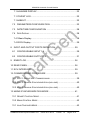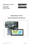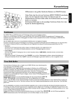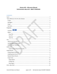
1
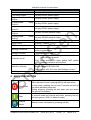
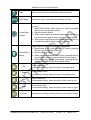
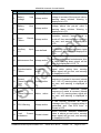
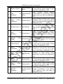
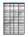
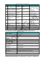
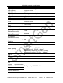
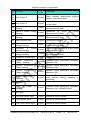
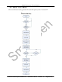
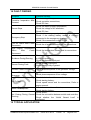
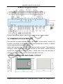
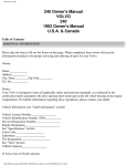
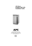
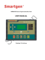
HGM6520 Genset Synchronization Unit USER MANUAL Smartgen Technology Chinese trademark English trademark Smartgen — make your generator smart Smartgen Technology Co., Ltd No. 28 Jinsuo Road Zhengzhou Henan Province P. R. China Tel: +86-371-67988888/67981888 +86-371-67991553/67992951/67992952 +86-371-67981000(overseas) Fax: 0086-371-67992952/67981000 Web: http://www.smartgen.com.cn http://www.smartgen.cn Email: [email protected] All rights reserved. No part of this publication may be reproduced in any material form (including photocopying or storing in any medium by electronic means or other) without the written permission of the copyright holder. Smartgen Technology reserves the right to change the contents of this document without prior notice. Software Version Date Version Note 2011-06-15 1.0 Original release. HGM6520 Automatic Control Module TABLE OF CONTENTS 1 SUMMARY ....................................................................................... 6 2 PERFORMANCE AND CHARACTERISTICS .................................. 6 3 SPECIFICATION .............................................................................. 7 4 KEYS DESCRIPTION ...................................................................... 8 5 OPERATION .................................................................................. 10 5.1 AUTOMATIC START/STOP SYNCHRONIZATION OPERATION .................. 10 5.1.1Automatic Mains Failure (AMF) ................................................. 10 5.1.2Remote Start Island Mode ......................................................... 11 5.1.3Remote Start Load Mode .......................................................... 11 5.2 MANUAL START/STOP SYNCHRONIZATION OPERATION ....................... 12 6 PROTECTION ................................................................................ 13 6.1 WARNINGS ..................................................................................... 13 6.2 SHUTDOWN ALARM ......................................................................... 16 6.3 ELECTRICAL TRIPS SHUTDOWN ........................................................ 17 7 PANEL CONFIGURATION............................................................. 19 7.1 LCD DISPLAY ................................................................................. 19 7.1.1Status Display ............................................................................ 19 7.1.2Engine Display .......................................................................... 19 7.1.3GENERATOR DISPLAY ............................................................ 20 7.1.4MAINS DISPLAY ....................................................................... 21 7.1.5SYNCHRONIZATION DISPLAY ................................................ 22 HGM6520 Genset Synchronization Unit ISSUE 2011-06-15 Version. 1.0 Page 3 of 47 HGM6520 Automatic Control Module 7.1.6ALARMS DISPLAY .................................................................... 22 7.1.7EVENT LOG .............................................................................. 22 7.1.8ABOUT ...................................................................................... 22 7.2 PARAMETERS CONFIGURATION .............................................. 23 7.3 DATE/TIME CONFIGURATION ................................................... 28 7.4 DATA DISPLAY................................................................................. 28 7.4.1Basic Display ............................................................................. 28 7.4.2ECU Display .............................................................................. 29 8 INPUT AND OUTPUT PORTS DEFINITION ................................. 29 8.1 CONFIGURABLE INPUT 1-9 ....................................................... 29 8.2 CONFIGURABLE OUTPUT 1-5 ................................................... 31 9 ENENT LOG ................................................................................... 36 10 REAR PANEL ................................................................................. 36 11 ECU INTERFACE ........................................................................... 39 12 COMMISSIONING PROCEDURE ................................................. 39 12.1 STEP1- SINGLE UNIT COMMISSIONING ............................................. 39 12.2 STEP 2- MANUAL SYNCHRONIZATION (NO-LOAD) ............................... 40 12.3 STEP 3- MANUAL SYNCHRONIZATION (ON-LOAD) ............................... 40 13 MAINS SYNCHRONIZATION MODE ............................................ 41 13.1 GENSET CONTROL MODE ................................................................ 41 13.2 MAINS CONTROL MODE................................................................... 42 13.1 LOAD TAKEOVER MODE ................................................................... 43 HGM6520 Genset Synchronization Unit ISSUE 2011-06-15 Version. 1.0 Page 4 of 47 HGM6520 Automatic Control Module 13.1 AMF MODE .................................................................................... 44 13.1 ISLAND MODE ................................................................................. 45 14 FAULT FINDING ............................................................................ 46 15 TYPICAL APPLICATION ................................................................ 46 16 COMMUNICATION INTERFACE ................................................... 47 17 CASE DIMENSIONS AND PANEL CUTOUT ................................ 47 HGM6520 Genset Synchronization Unit ISSUE 2011-06-15 Version. 1.0 Page 5 of 47 HGM6520 Automatic Control Module 1 SUMMARY HGM6520 controller is applicable for manual/auto synchronization system of generator and mains, which can achieve automatic start/stop, data measurement, alarm protection and ―four remote‖ (remote controlling, remote measuring, remote communication and remote adjustment). It adopts LCD display and optional Chinese–English interface with easy operation and reliable operation. The controller owns GOV (Engine Speed Governor) and AVR (Automatic Voltage Regulator) functions. Multiple working modes can be selected, such as genset fixed active power, reactive power/power factor output, mains peak shaving and uninterruptedly restore to mains supply. HGM6520 controller can accurately monitor various running status. When genset running is abnormal, it will disconnect bus bar and stop the genset. At the same time LCD displays the alarm information. HGM6520 controller based on 32-bit MPU design has SAE J1939 interface which can communicate with types of ECU (Engine Control Unit) with J1939 interface. Multiple parameters, like the engine speed, water temperature, oil temperature and oil pressure can be read directly via J1939 interface and displayed in LCD. Users do not need to install a sensor. Complex connections are reduced but accurate accuracy is ensured. 2 PERFORMANCE AND CHARACTERISTICS 32-bit MPU as the core, large LCD with back-light, optional English-Chinese display, push-button operation; Multiple running states under Auto mode: AMF (Automatic Mains Failure), Island Mode, Fixed Power, Peak Shaving Mode and Load Takeover Mode; Scheduling start and stop weekly/monthly. Commissioning with synchronization or without load can be chosen; Through SAE J1939 interface, can directly monitor ECU; RMS measuring, suitable for various occasions where electricity quantity is distorted; Accurate real-time measuring and display of electrical parameter, water temperature, oil pressure, fuel level and so on; Perfect mains protection: over/under frequency, over/under voltage, ROCOF and vector shift; HGM6520 Genset Synchronization Unit ISSUE 2011-06-15 Version. 1.0 Page 6 of 47 HGM6520 Automatic Control Module Control and protection function: automatic start/stop/synchronization, synchronous detection, load sharing and alarm protection; Maintenance due warning/shutdown alarm; Parameter setting: users are approved to adjust parameters. Meanwhile, the setting will be saved into the internal Flash memory and never lost even power off; For the engines without J1939, temperature, pressure and fuel level sensors also can be installed and used. Sensor curve also can be user defined; Contents in LCD can be defined when programmable input is active. Optional Chinese and English interface can input max. 10 Chinese characters or 20 English letters; Can configure digital input as close to activate or open to activate. Can configure digital output as normally open or normally closed; Logic output can be defined as continuous output or pulse output; With real-time calendar, clock and hour counter; Can save 99 sets of event logs in cycle which can be backtracked on the spot; Multi-level password protection to avoid incorrect operations by non-professionals; Parameters can be adjusted from front panel or configured via PC; Power supply range: (8-35) VDC, adapt to different starting battery voltage; RS485/232C communication interface uses MODBUS-RTU communication protocol to realize ―four remote‖ of the controller; Modular design, anti-flame ABS shell, plug-in terminals, embedded installation with compact structure and convenient mounting; 3 SPECIFICATION Items Working Voltage Power Consumption Alternator Voltage Input: 3 Phase 4 Wire 3 Phase 3 Wire Single Phase 2 Wire 2 Phase 3 Wire True RMS Accuracy Alternator Frequency. Speed Sensor Voltage Speed Sensor Frequency Contents DC8. 0V to 35. 0V, continuous <3W (Standby mode: ≤2W) 15V AC - 360 V AC (ph-N) 30V AC - 600 V AC (ph-ph) 15V AC - 360 V AC (ph-N) 15V AC - 360 V AC (ph-N) 1% 50/60Hz 1. 0 V to 24 V (RMS) Maximum 10,000 Hz HGM6520 Genset Synchronization Unit ISSUE 2011-06-15 Version. 1.0 Page 7 of 47 HGM6520 Automatic Control Module Items Start Relay Output Fuel Relay Output Programmable Output 1 Programmable Output 2 Programmable Output 3 Programmable Output 4 Programmable Output 5 Case Dimensions Panel Cutout Contents 16 Amp DC28V power supply 16 Amp DC28V power supply Relay Relay Relay Relay Relay CT Secondary Current Working Conditions Storage Condition Protection Level Insulation Intensity Net Weight 16 Amp DC28V power supply 16 Amp DC28V power supply 16 Amp DC28V power supply 16 Amp 250VAC passive output 16 Amp 250VAC passive output 260mm x 182mm x 57mm 214mm x 160mm Rated 5A Temperature: (-25~+70)°C Humidity: (20~93)% without condensation Temperature:(-30~+80)°C IP55: when waterproof rubber gasket added between controller and its panel IP42: when waterproof rubber gasket NOT added between controller and its panel Object: among input/output/power supply Quote standard: IEC688-1992 Test method: AC1.5kV/1min 3mA leakage current 0.90kg 4 KEYS DESCRIPTION Stop/Reset Pressing the key to stop the running genset; When an alarm occurs, pressing the key will reset alarm; In stop mode, pressing the key over 3 seconds will test all the panel indicators;(lamp test) During stopping, pressing the key again can shut down the genset immediately. Start In manual mode and manual test mode, pressing the key will start genset.( ONLY in Manual mode) Manual Mode Manual mode is activated by pressing this key. HGM6520 Genset Synchronization Unit ISSUE 2011-06-15 Version. 1.0 Page 8 of 47 HGM6520 Automatic Control Module Test Manual test mode is activated by pressing this key. Auto Mode Automatic mode is activated by pressing this key. Close/Open Genset Close/Open Mains Under manual mode, active when generator in normal running: 1. Stand-Alone Mode: when mains not closed, pressing the key can closed/open genset. 2. Synchronization Mode: a. When mains closed and genset open, pressing the key can synchronize genset with mains and close genset. b. When mains and genset both closed, pressing the key can transfer load to mains and open genset. Under manual mode, active when mains normal: 1. Stand-Alone Mode: when genset not closed, pressing the key can closed/open mains. 2. Synchronization Mode: a. When genset closed and mains open, pressing the key can synchronize mains with genset and close mains. b. When mains and genset both closed, pressing the key can transfer load to genset and open mains. Up Scroll screen Up; In parameter setting, press this key to increase value. Down Scroll screen Down; In parameter setting, press this key to decrease value. Left Scroll screen left; In parameter setting, press this key to shift cursor to left. Right Scroll screen right; In parameter setting, press this key to shift cursor to right. Confirm In parameter setting, pressing this key can confirm setting. HGM6520 Genset Synchronization Unit ISSUE 2011-06-15 Version. 1.0 Page 9 of 47 HGM6520 Automatic Control Module 5 OPERATION 5.1 Automatic Start/Stop Synchronization Operation Auto mode is activated by pressing key; an LED indicator beside the button will illuminate to confirm this operation. 5.1.1 AUTOMATIC MAINS FAILURE (AMF) Starting Sequence, 1. When mains abnormal, unit enters into ―Start Delay‖; 2. ―Start Delay‖ countdown is displayed in LCD; 3. When ―start delay‖ ends, preheat relay outputs (if fitted), and LCD shows ―Preheat Delay XX s‖; 4. When ―Preheat Delay‖ ends, the fuel relay outputs 1s(or via a start signal from ECU), then starter relay outputs; If the genset fails to start within ―Start Timer‖, the fuel relay and starter relay stop outputting and enter into ―Crank Rest Time‖ to wait for next cranking; NOTE: If the controller is configured as CANBUS active, then engine ECU will receive the start signal from CANBUS. 5. If failed to start within start attempts, the first row of LCD display is black and ―Fail to Start‖ alarm is displayed in LCD; 6. If crank disconnect any time of the start attempts, it will enter into ―Safety on Timer‖. During this period, such alarms like low oil pressure, high water temperature, low speed and charge failure, are inactive. After the ―Safety on Delay‖ ends, enter into Start Idle Delay‖ (if configured); NOTE: If the controller is configured as CANBUS active, engine speed can be read from ECU directly. 7. During the period of ―Start Idle Delay‖, under speed/frequency/voltage alarms are inactive. After the ―Start Idle Delay‖ is over, enter into ―Warm up Delay‖ (if configured); 8. When ―Warm up Delay‖ is over, if genset normal, indicator will illuminate. When voltage and frequency of the alternator reach the load demand, open mains and close genset, genset takes load and power indicator illuminates to enter into normal running; when voltage or frequency is abnormal, controller will alarm to shutdown. (details of alarm is displayed in LCD) Auto Stopping Sequence, HGM6520 Genset Synchronization Unit ISSUE 2011-06-15 Version. 1.0 Page 10 of 47 HGM6520 Automatic Control Module 1. When mains normal, GOV and AVR will be adjusted by controller in order to make genset synchronous with mains. When synchronization condition is met, closing signal is initiated to synchronization genset with mains and ―Stop Delay‖ begins. Genset mode or mains mode output can be selected; 2. When ―Stop delay‖ is over, controller will gradually transfer load to mains, send open signal, and then ―Cooling Delay‖ begins. When the ―Cooling Delay‖ is over, unit enters into ―Stop Idle Delay‖; 3. During ―Stop Idle Delay‖ (if configured), idle relay is energized to output. If the controller is configure as CANBUS active, CANBUS can execute stop function; 4. During ―ETS Delay‖, the ETS relay is energized to output. The fuel relay output is disconnected; 5. During ―genset at rest timer‖, automatically judge if unit is steady or not; 6. When genset at rest, enter into standby state; if the unit fails to stop, the controller will alarm. (―Fail to Stop‖ is displayed in LCD) 5.1.2 REMOTE START ISLAND MODE 1) When remote start input is active, enter into ―Start Delay"; 2) As for starting sequence, please refer to 2-7 of Automatic Mains Failure (AMF) ; 3) When hi-speed ―Warm Up Delay‖ ends, indicator will illuminate when genset normal; GOV and AVR are adjusted to make genset synchronous with mains. When synchronization condition is met, controller will send closing signal to synchronization genset with mains. After transferring load to genset, open mains; 4) When remote start input is inactive, enter into ―Stop Delay‖; 5) When ―Stop Delay‖ is over, genset turns to synchronization with mains. Controller will transfer load to mains and then open genset; 6) Generator stops normally. 5.1.3 REMOTE START LOAD MODE 1) When remote start input is active, enter into ―Start Delay‖; 2) As for starting sequence, please refer to 2-7 of Automatic Mains Failure (AMF); 3) When ―Warm Up Delay‖ ends, indicator will illuminate if genset normal; GOV and AVR are adjusted to make genset synchronous with mains. When synchronization condition is met, controller will send closing signal to synchronization genset with mains. Three modes can be selected as the following (PC software configuration): a) Genset Mode: Genset maintains constant active power, inactive power/power factor output; HGM6520 Genset Synchronization Unit ISSUE 2011-06-15 Version. 1.0 Page 11 of 47 HGM6520 Automatic Control Module b) Mains Mode: mains load is limited under default and the extra load is shared by Genset(peak shaving mode) c) Load Receiving: when genset has totally received mains load, open mains. 4) when remote start input is inactive, enter into ―Stop Delay‖; 5) When ―Stop Delay‖ ends, close genset, and then unit stops normally; 5.2 Manual Start/Stop Synchronization Operation 1. Manual mode is activated by pressing key and an LED indicator beside the key will illuminate to confirm this operation. Press key to start the genset; 2. Preheat relay outputs (if configured), LCD screen shows ―Preheat Delay XX s‖; 3. When preheat delay ends, fuel relay outputs 1s (or via a start signal from ECU), and then start relay outputs; if the failed to start within ―start times‖, both the fuel relay and start relay stop outputting and enter into “Crank Rest Time‖ to wait for the next cranking; NOTE: If the controller is configured as CANBUS active, engine ECU will receive a start signal from CANBUS. 4. If failed to start within start attempts, the first row of LCD display is black and ―Fail to Start‖ alarm is displayed in LCD; 5. If crank disconnect any time of the start attempts, it will enter into ―Safety on Timer‖. During this period, such alarms like low oil pressure, high water temperature, low speed and charge failure, are inactive. After the ―Safety on Delay‖ ends, enter into Start Idle Delay‖ (if configured); NOTE: If the controller is configured as CANBUS active, engine speed can be read from ECU directly. 6. During the period of ―Start Idle Delay‖, under speed/frequency/voltage alarms are inactive. After the ―Start Idle Delay‖ is over, enter into ―Warm up Delay‖ (if configured); 7. When ―Warm up Delay‖ is over, genset waits for taking load; 8. Press key (close/open genset), when ―Warm up Delay‖ is over, if genset normal the indicator will illuminate. When voltage and frequency of the alternator reach the load demand, closing relay of genset outputs, genset is taking load and power supply indicator illuminates to enter into normal running; Pressing key during synchronous running can adjust GOV and AVR to make genset HGM6520 Genset Synchronization Unit ISSUE 2011-06-15 Version. 1.0 Page 12 of 47 HGM6520 Automatic Control Module synchronous with mains. When synchronization condition is met, closing signal is initiated to synchronization genset with mains. Genset mode or mains mode output can be selected; 9. Pressing key during running can control mains closed/open. Under synchronous running (mains open), press this key, genset turns to synchronize with mains and close mains. When mains closed, press the key again to transfer mains to genset and open mains; 10. Press key, open genset to shut down the unit. 6 PROTECTION When an alarm occurs, the common alarm indicator (if configured) will illuminate and the alarm information will be displayed in LCD. 6.1 Warnings Warnings are non-critical alarm conditions and do not affect the operation of the generator system. They serve to draw the operators’ attention to an undesirable condition. Warning alarms is shown as the below: No Items Range 1 Genset Current Over 2 Fail To Stop After stop delay timer is over 3 Low Fuel Level Always active 4 Charge Failure From start idle to stop idle 5 From crank Loss Of Speed disconnect to Signal stop idle Always active HGM6520 Genset Synchronization Unit Description When controller detects a generator output current in excess of the pre-set trip a warning alarm initiates. Warning is displayed in LCD. When genset stop delay timer is over, if genset output is power on and oil pressure is not 0, warning alarm signal will be send and details is displayed in LCD. When controller detects fuel level in excess of the pre-set value a warning alarm initiates. Warning is displayed in LCD. When controller detects charge voltage in excess of the pre-set value a warning alarm initiates. Warning is displayed in LCD. When controller detected the speed of genset is 0, warning alarm signal will be sent, and warning is displayed in LCD. ISSUE 2011-06-15 Version. 1.0 Page 13 of 47 HGM6520 Automatic Control Module No Items Range 6 Battery Voltage Low 7 Battery Voltage Over 8 Open Failure Genset 9 Auxiliary 1-9 10 Maintenance Due Always active 11 Synchronization Failure Synchrony active 12 Genset Phase-Sequence Error Genset active 13 Mains Phase-Sequence Error Mains 14 ECU Warning Always active 15 Load Current Genset closed Unbalance Input Always active Always active Always active User defined HGM6520 Genset Synchronization Unit active Description When controller detects start battery voltage in excess of the pre-set value a warning alarm initiates. Warning is displayed in LCD. When controller detects start battery voltage above the pre-set value a warning alarm initiates. Warning is displayed in LCD. When break-off delay timer is over, and controller couldn’t detect signal of break off, then warning alarm signal will be sent, and warning is displayed in LCD. When controller detected auxiliary input 1-9 warning input, warning alarm signal will be sent, and warning is displayed in LCD. When engine accumulated run time or days exceeds preset maintenance time or days, warning alarm signal will be sent and displayed in LCD. *1 When controller can’t detect synchrony signal within setting time, warning alarm signal will be sent, and warning is displayed in LCD. When controller detected phase sequence of genset is incorrect (should be L1 L2 L3), warning alarm signal will be sent, and warning is displayed in LCD. When controller detected phase sequence of mains is incorrect (should be L1 L2 L3), warning alarm signal will be sent, and warning is displayed in LCD. If the module receives an ―error‖ message from ECU, a warning alarm is generated, and ―Can ECU error‖ is shown in LCD. When controller detected unbalance value is above pre-set value, warning alarm signal will be sent, and warning is displayed in LCD. ISSUE 2011-06-15 Version. 1.0 Page 14 of 47 HGM6520 Automatic Control Module No Items Range 16 High Temp Warn From start idle to stop idle 17 Low Temp Warn Always active 18 Low Oil Pressure From start idle to stop idle 19 Over Speed Always active 20 Under Speed From wait for loading to cooling timer 21 Genset Over Always active Frequency 22 From wait for Genset Under loading to Frequency cooling timer 23 Genset Voltage 24 Genset Voltage 25 Loss of Excitation Always active 26 Mains Error Over Always active From wait for Under loading to cooling timer Closed Always active HGM6520 Genset Synchronization Unit Description When controller detected engine’s temperature is over than pre-set, warning alarm signal will be sent, and warning is displayed in LCD. When controller detected engine’s temperature is less than pre-set, warning alarm signal will be sent, and warning is displayed in LCD. When controller detected engine’s oil pressure is less than pre-set, warning alarm signal will be sent, and warning is displayed in LCD. When controller detected engine’s speed is above pre-set, warning alarm signal will be sent, and warning is displayed in LCD. When controller detected engine’s speed is less than pre-set, warning alarm signal will be sent, and warning is displayed in LCD. When controller detected engines voltage frequency is above pre-set, warning alarm signal will be sent, and warning is displayed in LCD. When controller detected engines voltage frequency is less than pre-set, warning alarm signal will be sent, and warning is displayed in LCD. When controller detected engines voltage is over than pre-set, warning alarm signal will be sent, and warning is displayed in LCD. When controller detected engines voltage is less than pre-set, warning alarm signal will be sent, and warning is displayed in LCD. When controller detected engines negative reactive power is over than pre-set, warning alarm signal will be sent, and warning is displayed in LCD. When mains closed output, closed input cannot be detected. ISSUE 2011-06-15 Version. 1.0 Page 15 of 47 HGM6520 Automatic Control Module No 27 Items Range Mains Open Error Always active Description When mains open output, disconnection input cannot be detected. When maintenance time up, configure an input port as ―reset maintenance alarm‖, and then it can be removed by an active grounding pulse signal. 6.2 Shutdown Alarm Shutdown alarm will not disappear until manual reset to remove. As soon as ―Alarm shutdown‖ is generated, genset will immediately shutdown. No Items Range Description When controller detects emergency stop alarm signal, alarm signal is sent, 1 Emergency Stop Always active and alarm is displayed in LCD. 2 3 4 5 6 7 8 9 When controller detects engine’s water From the start temperature is over pre-set, alarm High Temperature idle to stop idle signal is sent, and alarm is displayed in LCD. When controller detects engine’s oil From the start pressure is under pre-set, alarm signal Low Oil Pressure is sent, and alarm is displayed in LCD. idle to stop idle Genset Speed Over Always active From genset Genset Under wait for Speed loading to cooling timer From genset Loss Of Speed start Signal successfully to stop idle When controller detects engine’s speed is over pre-set, alarm signal is sent, and alarm is displayed in LCD. When controller detects engine’s speed is under pre-shutdown setting, alarm signal is sent, and alarm is displayed in LCD. When controller detects engine’s speed is 0, alarm signal is sent, and alarm is displayed in LCD. When controller detects voltage Always active frequency is over pre-set, alarm signal is sent, and alarm is displayed in LCD. From genset When controller detects voltage Genset Under wait for frequency is under pre-set, alarm Frequency loading to signal is sent, and alarm is displayed in cooling timer LCD. When controller detects voltage is over Genset Over Always active pre-set, alarm signal is sent, and alarm Voltage is displayed in LCD. Genset Frequency Over HGM6520 Genset Synchronization Unit ISSUE 2011-06-15 Version. 1.0 Page 16 of 47 HGM6520 Automatic Control Module No 10 11 12 13 14 15 16 17 18 19 Items Range Description From genset When controller detects voltage is Genset Under wait for under pre-set, alarm signal is sent, and Voltage loading to alarm is displayed in LCD. cooling timer When controller detects current is over Genset Over Always active pre-set, alarm signal is sent, and alarm Current is displayed in LCD. Genset fails to start within pre-set Failed within Fail To Start attempts, alarm signal is sent, and start attempts shutdown alarm is displayed in LCD. When controller detects oil pressure Oil Pressure Always active sensor is open, alarm signal is sent, Sensor Open and alarm detail is displayed in LCD. When controller detects alarm from Auxiliary Input 1-9 Users defined input ports 1-9, alarm signal is sent, and alarm is displayed in LCD. When controller can’t detect ECU, When CANBUS alarm signal is sent, and alarm is configured as CANBUS Error displayed in LCD. This fault maybe active and caused by Can Bus open circuit, short genset is fired. circuit or error connection. When controller detects load current Load Current when genset imbalance value is over pre-set, alarm Unbalance closed signal is sent, and alarm is displayed in LCD. When CANBUS When receives a shutdown alarm from configured as engine’s ECU via CANBUS alarm ECU Alarm active and signal is sent by controller, and alarm is engine is fired. displayed in LCD. Genset Closed When genset closed output, closed Always active Error input cannot be detected. When genset open output, Genset Open Always active disconnection input cannot be Error detected. 6.3 Electrical Trips Shutdown Electrical trips are latching and stop the Generator but in a controlled manner. On initiation of the electrical trip condition the module will de-energies the ‘Close Generator’ Output to remove the load from the generator. No Items Range Description When controller detects current is over Genset Over 1 Always active pre-set, alarm signal is sent, and alarm Current is displayed in LCD. *1 HGM6520 Genset Synchronization Unit ISSUE 2011-06-15 Version. 1.0 Page 17 of 47 HGM6520 Automatic Control Module synchronization active 2 Reverse Power 3 Loss Excitation 4 Load Current Genset closed Unbalance 5 Auxiliary Input 1-9 User defined 6 Loss Excitation 7 Genset Power 8 Inverse Power Always active 9 Mains Frequency Always active 10 Mains Under Always active Frequency 11 Mains Voltage Over 12 Mains Voltage Under 13 ROCOF Protection Of synchronization active Of Over Over Always active Always active Always active Always active Synchronization active HGM6520 Genset Synchronization Unit When controller detects inverse power is over pre-set, alarm signal is sent, and alarm is displayed in LCD. When controller detects negative reactive power is over pre-set, alarm signal is sent, and alarm is displayed in LCD. When controller detected load current imbalance value is over pre-set, alarm signal is sent by controller, and alarm is displayed in LCD. When controller detects auxiliary input port 1-9 trip alarm and input, alarm signal is sent, and alarm is displayed in LCD. When controller detects negative reactive power is over pre-set, alarm signal is sent, and alarm is displayed in LCD. When controller detects power is over pre-set, alarm signal is sent, and alarm is displayed in LCD. When controller detects inverse power is over pre-set, alarm signal is sent, and alarm is displayed in LCD. When controller detects mains frequency is over pre-set, alarm signal is sent, and alarm is displayed in LCD. When controller detects mains frequency is under pre-set, alarm signal is sent, and alarm is displayed in LCD. When controller detects mains voltage is over pre-set, alarm signal is sent, and alarm is displayed in LCD. When controller detects mains voltage is under pre-set, alarm signal is sent, and alarm is displayed in LCD. When controller detects the rate of change of frequency is over pre-set, alarm signal is sent, and alarm is displayed in LCD. ISSUE 2011-06-15 Version. 1.0 Page 18 of 47 HGM6520 Automatic Control Module 14 VS Protection Synchronization active When controller detects vector shift is over pre-set, alarm signal is sent, and alarm is displayed in LCD. NOTE *1:For example, if set ―over current‖ as 110% and trip shutdown delay as one hour, when load current is over 110%, the delay begins. But when current cannot fall down within one hour, electrical trip occurs and engine stops. Higher current will cause short trip. Typically, when load current is 2 times higher than full load current, switch will open after 36 seconds, and then engine stops. 7 PANEL CONFIGURATION 7.1 LCD Display 7.1.1 STATUS DISPLAY STATUS 1-1 First Screen Display Controller Modes: STOP/MANUAL/AUTO Mode STOP MODE GENSET AT REST Genset Working Status GB OPEN MB OPEN Open/Closed Indication of genset/Mains STATUS 1-2 UL-N 0V 0.0 A UL-L 0V 0.00Hz Pf = 0.00L 0.0 kW STATUS 1-3 F S E123456789 INPUT OUTPUT Second Screen Display Generator Average Phase Voltage/Current Generator Average Line Voltage/Frequency Generator Average Power Factor, Total Active Power Third Screen Display F:fuel output, S:start input, E:emergency stop, auxiliary input/output 1~9 Input port status, close/open Output port status, close/open 7.1.2 ENGINE DISPLAY ENGINE 2-1 First Screen Display SPEED 0 RPM Engine Speed BATTERY 12.0 V Start Batterer Voltage CHARGE D+ 0.0 V AC Charger D+ Voltage ENGINE 2-2 Second Screen Display OIL PRESSURE Engine Oil Pressure HGM6520 Genset Synchronization Unit ISSUE 2011-06-15 Version. 1.0 Page 19 of 47 HGM6520 Automatic Control Module 0 kPa 0.0 Bar 0 Psi ENGINE 2-3 Third Screen Display OIL LEVEL % Oil Level TEMPERATURE 0℃ Oil Temperature 0℉ ENGINE 2-4 Fourth Screen Display STARTS 00000 num Accumulated Cranking Times HOURS RUN Accumulated Run Times: Hours/Minutes/Seconds 0000:00:00 7.1.3 GENERATOR DISPLAY GENERATOR 3-1 First Screen Display UL-L 0 0 0 V Phase Voltage L1-N L2-N L3-N UL-N 0 0 0 V Line Voltage L1-L2 L2-L3 L3-L1 F = 0.00Hz 0 RPM Generator Frequency, Engine Speed GENERATOR 3-2 IL 0.0 0.0 0.0 A Pf 0.00 0.00 0.00 APf 0.00L Second Screen Display 3 Phase Current L1 L2 L3 3 Phase Power Factor L1 L2 L3 Generator Frequency Power Factor GENERATOR 3-3 Third Screen Display kW 0.0 0.0 0.0 3 Phase Active Power L1 L2 L3 Generator Total Active Power, Pre-Set Active Power TkW 0.0 Ramp 3.0 Percentage kW% 0.0 Tgt% 0.0 active Power Output Percentage, Object Active Power Percentage GENERATOR 3-4 kVar 0.0 0.0 0.0 TkVar 0.0 Ramp 0.0 kVar% 0.0 Tgt% 0.0 GENERATOR 3-5 kVA 0.0 0.0 0.0 TkVA 0.0 Fourth Screen Display 3 Phase Reactive Power L1 L2 L3 Total Reactive Power, Pre-Set Reactive Power Percentage Reactive Power Output Percentage , Object Reactive Power Percentage Fifth Screen Display 3 phase apparent power L1 L2 L3 Total apparent power speed regulation voltage Output Percentage, Voltage HGM6520 Genset Synchronization Unit ISSUE 2011-06-15 Version. 1.0 Page 20 of 47 HGM6520 Automatic Control Module GOV% 0.0 AVR% 0.0 regulation Output Percentage GENERATOR 3-6 kWh 0000000.0 kVAh 0000000.0 kVarh 0000000.0 Sixth Screen Display Accumulated Active Electrical Power Accumulated Apparent Electrical Power Accumulated Reactive Electrical Power GENERATOR 3-7 PHASE SEQUENCE: LN1-LN2-LN3 000-120-240° Seventh Screen Display Generator Phase-Sequence 7.1.4 MAINS DISPLAY MAINS 4-1 First Screen Display UL-L 0 0 0 V Mains 3 Phase Phase Voltage L1-N L2-N L3-N UL-N 0 0 0 V Mains 3 Phase Line Voltage L1-L2 L2-L3 L3-L1 F = 0.00Hz Mains Frequency IL Pf MAINS 0.0A 0.00L 4-2 Second Screen Display Mains Phase Current L1 Mains Power Factor MAINS 4-3 kW 0.0 kW% 0.0 kVar 0.0 kVar% 0.0 kVA 0.0 Third Screen Display Total Active Power, Active Power Output Percentage Total Reactive Power, Reactive Power Output Percentage Mains Apparent Power MAINS 4-4 PHASE SEQUENCE: LN1-LN2-LN3 000-120-240° Fourth Screen Display Mains Phase-Sequence MAINS 4-5 ROCOF 0.00Hz 10.00Hz VECTOR 0.0°64.2° Fifth Screen Display Mains Frequency Shift Mains Vector Shift MAINS 4-6 TAKEOVER MODE kW 0.0% 103kW kVar 0.0%72.2kVar Sixth Screen Display Current Genset Mode Pre-set active power percentage, actual value Pre-set reactive power percentage, actual value HGM6520 Genset Synchronization Unit ISSUE 2011-06-15 Version. 1.0 Page 21 of 47 HGM6520 Automatic Control Module 7.1.5 SYNCHRONIZATION DISPLAY SYNCHROSCOPE 5-1 First Screen Display VOLT DIFF +0.1 V √ Voltage difference between genset and mains FREQ DIF +0.01 Hz √ Frequency difference between genset and mains PHASE DIFF +0.1° √ Phase difference between genset and mains 7.1.6 ALARMS DISPLAY ALARMS 6-1 First Screen Display ALARMS:(01/02) Total Number of Alarms SHUTDOWN ALARM Alarm Types: Warning/Shutdown/Trip OP SENSOR OPEN Alarm Description ALARMS 6-2 ALARMS:(02/02) SHUTDOWN ALARM GENERATOR CLOSED ERROR 7.1.7 EVENT LOG EVENTS 7-1 RECORDS: (01/02) OVER CURRENT TRIP 2010-12-18 21:31:55 Second Screen Display Total Number of Alarms Alarm Types: Warning/Shutdown/Trip Alarm Description First Screen Display Total Number of Records Error Types Record Time EVENTS 7-2 RECORDS: (02/02) GENERATOR CLOSED ERROR 2010-12-18 08:11:07 Second Screen Display Total Number of Records Error Types Record Time 7.1.8 ABOUT ABOUT 8-1 MODEL:HGM6520 SOFTWARE:V4.0.2 11-03-08 (5) 03:11:32 First Screen Display Model: HGM6510, HMG6520 Module Software Version Current Clock ABOUT 8-2 HARDWARE:V1.3 Second Screen Display Module Hardware Version CPU TEMP:34℃/93℉ Module Inner Temperature ISSUE DATE: 2011-06-24 Original Release HGM6520 Genset Synchronization Unit ISSUE 2011-06-15 Version. 1.0 Page 22 of 47 HGM6520 Automatic Control Module 7.2 PARAMETERS CONFIGURATION Press and hold, and then pressing Pressing or can enter into the password interface. can input the password, (range of 0~9), cursor to the left or right, and press or to shift in the fourth to confirm. Parameter setting will be entered if password is correct, or directly exit with wrong password. (Factory default is 1234 and user can change it) Pressing and screen press press or can scroll screen up or down. Under current parameter and enter into the item. The first digital turns black display. Then, to increase or decrease the value, and press the cursor to the right or left. At last, press or to shift to confirm this setting at the last digital. In parameter configuration, pressing can exit this menu directly and back to main menu. Parameters list: No. Items Low Oil Pressure 01 (Warning) Range Default (1-999)kPa 02 Low Oil Pressure (Shutdown) 03 High Temperature (81-139)ºC (Warning) 04 05 06 07 08 09 (0-997)kPa 124kPa/18.0PSI Return value: 138kPa/20.0PSI 103kPa/14.9PSI Setting standard: shutdown<warn <return 93ºC/194ºF Return 88°C/190°F 98ºC/203ºF Setting standard: shutdown>warn >return (0-100)% 10% Analog value (0-9999)s (0-300)s (3-60)s (3-60)s 5s 0s 8s 10s Timer Timer Timer Timer High Temperature (82-140)ºC (Shutdown) Low Fuel Level (Warning) Start Delay Preheat Delay Crank Time Crank At Rest Notes HGM6520 Genset Synchronization Unit ISSUE 2011-06-15 Version. 1.0 value: Page 23 of 47 HGM6520 Automatic Control Module No. Items 10 Safety On Timer Over Speed/Shoot 11 Time 12 Start Idle Timer 13 Warm Up Timer 14 Stop Delay 15 Cooling Timer 16 Stop Idle Timer ETS Solenoid 17 Hold Time 18 Over Stop Delay Genset Transient 19 Delay Battery Low 20 Voltage Delay Battery Over 21 Voltage Delay Inverse Power 22 Delay 23 24 25 Range (5-60)s (0-10)s Default 10s 2s Timer (0-3600)s (0-3600)s (0-9999)s (0-3600)s (0-3600)s (0-120)s 10s 30s 30s 60s 10s 0s Timer Timer Timer Timer Timer (10-120)s (0-30)s 30s 5s Timer (0-9999)s 60s (0-9999)s 60s (0-300)s 10s Genset Low Volt (50-360)V (Warning) Genset Low Volt (50-360 )V (Shutdown) Genset Over Volt (50-360)V (Warning) Timer Timer 265V Return value:253V 273V Genset Low Freq (0-74.8)Hz 40.0Hz (Shutdown) Genset High Freq (0.1-74.9)Hz 55.0Hz (Warning) HGM6520 Genset Synchronization Unit Timer Under shutdown Genset Low Freq (0.1-74.9)Hz 42.0Hz (Warning) 30 Timer 184V 27 Genset High Freq (0.2-75)Hz (Shutdown) Timer 196V 26 29 Timer Load value: 207V Setting standard: Shutdown <warning <load. Genset Over Volt (50-360)V (Shutdown) 28 Notes 57.0Hz ISSUE 2011-06-15 voltage Setting standard: shutdown <warning <return Load value:45.0Hz Setting standard: Shutdown <warning <load. Under frequency shutdown Return value:52.0Hz Setting standard: shutdown>warn >return Version. 1.0 Page 24 of 47 HGM6520 Automatic Control Module No. 31 32 33 34 35 36 37 38 39 40 Items Range Over Current (50-120)% Percentage Flywheel Teeth (10-500) Under Speed (Warning) Default 100% 118 (1-5999)RPM 1350RPM Under Speed (0-5998)RPM 1270RPM (Shutdown) Over Speed (1-5999)RPM 1650RPM (Warning) Over Speed (2-6000)RPM 1710RPM (Shutdown) Over Speed/ Shoot Percent Battery Low Volt (Warning) Battery Over Volt (Warning) Charge Failure (Warning) Notes Analogy Value Used for detecting crank disconnection. Return value: 1380RPM Setting standard: Shutdown <warning <load. Under speed shutdown Return value: 1620RPM Setting standard: Shutdown >warn >return (0-10)% 10 Analogy Value (0-39.9)V 8.0V Analogy Value (0.1-40)V 33.0V Analogy Value (0-39)V 6.0V Analogy Value 41 Language Select (0-1) 0 0:Chinese 1:English 42 Password (0-9999) 1234 Numerical Value 43 Module Priority (0-19) 0 Upper to lower (1-254) 1 RS485 communication address 5-6000:5A 500A (0-9999) 345 kW (0-9999) 258 kVar 44 45 46 47 Module Address(RS485) Current Transformer Rated Active Power Rated Reactive Power 48 Load Slope (0-100)% 3% 49 Full Power Start (0-100)% 80% 50 Low Shutdown (0-100)% 50% Power HGM6520 Genset Synchronization Unit ISSUE 2011-06-15 Load Current: 500A Ramp-up/ramp-down to load of genset For scheduling unit to start. For scheduling unit to stop. Version. 1.0 Page 25 of 47 HGM6520 Automatic Control Module No. 51 52 53 54 55 56 57 58 59 60 61 Items Range Synch Positive (0-2)Hz Freq Difference Default Notes Frequency difference of genset and mains. If within the range, frequency is synchronous. Voltage difference of genset and mains. Phase difference of genset and mains. If synchronization is over preset delay, an alarm will be initiated. 0.2Hz Synch Negative (0-2)Hz Freq Difference 0.1Hz Synch (0-20)V Voltage Difference Synch (0-20)° Phase Difference Fail to Synchronize (5-300)s Delay 0:330k, MSC Baud Rate 1:250k, 2:125k Mains Transient (0-30)s Delay Mains Under Volt (50-360)V Mains Over Volt (50-360)V Mains Under Freq (0-75)Hz Mains Over Freq (0-75)Hz 3V 10° 60s Baud rate module. 0 of MSC Mains normal or abnormal delay Mains under voltage Mains over voltage Mains under frequency Mains over frequency 2s 184V 276V 45Hz 55Hz Other parameters configuration (only configured by software via PC) Items Module Address Alternator Select Number of Poles Magnetic Pickup Sensor Select Start Times Voltage Transformer Fuel Pump Control Digit Input 1 Default 1 Yes 4 Yes Digit Input 4 Digit Input 5 Digit Input 6 3 No No Remote start on load, close to activate Low oil pressure alarm, close to activate, active from safety on timer. High temperature alarm, close to activate, active from safety on timer. Closed generator auxiliary input, close to activate Indication, close to activate Working mode select, close to activate Digit Input 7 Indication, close to activate Digit Input 8 Indication, close to activate Digit Input 2 Digit Input 3 HGM6520 Genset Synchronization Unit ISSUE 2011-06-15 Version. 1.0 Page 26 of 47 HGM6520 Automatic Control Module Digit Input 9 Digit Output 1 Digit Output 2 Digit Output 3 Digit Output 4 Digit Output 5 LED1 LED2 LED3 Indication, close to activate Genset normal voltage Common alarm Idle/high-speed control Closed generator output Open generator output System in automatic mode Fail to start alarm Common shutdown alarm LED4 Common alarm Overload Current Delay Timer Delay Rate Action (Over Current) Genset Frequency (Starter Disconnect) Engine Speed (Starter Disconnect) Oil Pressure (Starter Disconnect) Detect Oil Pressure During Cranking 100%(500A) 36 Electrical trip 15Hz 450RPM Not used No Scheduled Start/Stop No Mains Splitting R.O.C.O.F: 0.2Hz/s V.S: 6.0° Mains under volt:209V, 0.1s delay Mains over volt:253V, 0.1s delay Mains under frequency: 47.1Hz, 0.1s delay Mains over frequency: 50.5Hz, 0.1s delay MSC ID 0 GOV 0V AVR 0V Frequency Synchronization PID Voltage Synchronization PID Configured by HGM6500 software Active Power PID Reactive power PID HGM6520 Genset Synchronization Unit ISSUE 2011-06-15 Version. 1.0 Page 27 of 47 HGM6520 Automatic Control Module 7.3 DATE/TIME CONFIGURATION Press key and key simultaneously and enter into date/time configuration. The first digital of the fourth row is black display. Press or to input corresponding number (range of 0~9), pressing ―√‖ can shift to the right, ―√‖ again at last to confirm, and then date and time has been restored and exit. Press to exit directly without saving. The date/time configuration order: Year/ Month/Date/ (Week)/ Hour/Minute/Second NOTE: Parameters and the date/time configuration must be in STOP mode. 7.4 Data Display 7.4.1 BASIC DISPLAY Engine Speed Oil Pressure Engine Temperature Fuel Level Start Battery Voltage Charger Voltage Engine Hours Run Engine Start Times Generator Phase Voltage (L1-N, L2-N, L3-N) Generator Line Voltage (L1-L2, L2-L3, L3-L1) Generator Frequency Generator Current (L1, L2, L3) Generator Single Phase Active Power (L1, L2, L3) Generator 3 Phase Total Active Power Each Phase Power Factor (L1, L2, L3) Average Power Factor Generator Single Phase Reactive Power (L1, L2, L3) Generator 3 Phase Total Reactive Power Generator Accumulative Total Active/Reactive/Apparent power Generator Phase Sequence Mains Phase Voltage (L1-N, L2-N, L3-N) Mains Line Voltage (L1-L2, L2-L3, L3-L1) Mains Total Active Power HGM6520 Genset Synchronization Unit ISSUE 2011-06-15 Version. 1.0 Page 28 of 47 HGM6520 Automatic Control Module Mains Total Reactive Power Mains Total Apparent Power Rate of Change of Frequency (R.O.C.O.F) Vector Shift (VS) Mains Frequency Mains Phase Sequence 7.4.2 ECU DISPLAY Oil Temperature Coolant Pressure Inlet Temperature Exhaust Temperature Supercharger Temperature Fuel Pressure Fuel Consumption Total Fuel Consumption 8 INPUT AND OUTPUT PORTS DEFINITION 8.1 CONFIGURABLE INPUT 1-9 No Type 0 User Defined 1 Alarm Mute Description The input is configured to perform an auxiliary function, this may be any of the following: Indication:(annunciation only, not alarm or shutdown) Warning:(Alarm only, not shutdown) Shutdown:(Alarm and shutdown) Electrical Trip:(Alarm/off-load generator followed by shutdown after cooling) Never active: This switches off the input if not in use. Always active: The input selected to be an indication or alarm even when the module is in the STOP/RESET MODE. Active from starting: The Auxiliary input is only active once an attempt to start the generator is made. It will remain active until the generator is at rest again. Active from safety on: Auxiliary inputs are only active once safety on timer is over. When active, this will disable an output configured to 'audible alarm', without resetting the module’s HGM6520 Genset Synchronization Unit ISSUE 2011-06-15 Version. 1.0 Page 29 of 47 HGM6520 Automatic Control Module 2 3 4 Reset Alarm AC Frequency (50/60Hz) alarm condition. When an alarm is active, it will be cleared. Select AC Voltage Select 5 Auto Return Inhibit 6 Auto Start Inhibit 7 8 9 10 11 12 13 14 15 16 17 18 19 20 21 22 23 Reserved For some EFI engines with CANBUS In AUTO mode, after the normal operation of generator, when input is active, automatic shutdown is not allowed. In AUTO mode, when input is active, automatic startup is not allowed. Mains Failure Auxiliary (Reserved) Input Genset Closed Connect to auxiliary contacts of genset with load Auxiliary Input switch. When input is active, closed generator will be Genset On Load Inhibit inhibited. Only for some EFI engines with CANBUS, when Droop Enable active, allow to droop. When input is active, all LED indicators will Lamp Test illuminate. Mains Closed Auxiliary Connect to auxiliary contacts of mains with load Input switch Mains On Load Inhibit (Reserved) When the input is effective, not all keys on its Panel Lock function In AUTO mode, when input is active, genset can be Remote Start (Unload ) automatically started to normal operation. When inactive, genset can be stopped. In automatic mode, when input is active, genset can be automatically started to normal operation Remote Start (On-Load ) and divided into the bus, only when inactive, genset can be stopped. In AUTO mode, when input is active, all the Remote Start On Load synchronous units are started according to PRI. (Demand) Then according to the load, units automatically increase or decrease units. In AUTO mode, when input is active, regular start is Scheduling Run Inhibit inhibited Analog Mains Active Reserved Analog Automatic Key Analog Manual Key An outside push button (not self-locking ) can be connected and analog panel buttons operation Analog Shutdown Key Analog Test Key HGM6520 Genset Synchronization Unit ISSUE 2011-06-15 Version. 1.0 Page 30 of 47 HGM6520 Automatic Control Module 24 25 26 Analog Start Key Analog Closed Key Analog Open Key 27 MSC Alarm Inhibit 28 29 30 31 32 33 34 35 36 37 38 39 When the MSC disconnect or data error occurs, prohibit sending a warning signal. Working Mode Select When input is active, the highest priority. When input is active, controller will reset Reset Maintenance maintenance time as default values and alarm is Alarm cleared. Remote Island Start When input is active, start mode is island mode Mains Synchronization Reserved Mode Speed Up Input Reserved Speed Down Input Reserved Voltage Up Input Reserved Voltage Down Input Reserved Black Start Input Reserved When the input is active, controller is in automatic Auto Mode Input mode and other modes are inactive. Shutdown Alarm Inhibit When the input is active, all the alarms are inactive. Reserved NOTE: Configurable input 1-9 cannot be defined as same item (Not Used and User Defined excluded), otherwise incorrect function will occur. 8.2 CONFIGURABLE OUTPUT 1-5 Each output port has the same option; and can be defined as the same content. No Type Description 00 Not Used In Emergency Stop or Over-speed alarm, stop engine 01 Air Flap Relay to let air in. This output is intended to drive an external Klaxon or alarm indicator and will be active upon the module triggering a warning, shutdown or electrical trip alarm. 02 Audible Alarm This external alarm can be ―muted‖, without resetting the module’s alarm condition by activating an auxiliary input that has been configured to ―Mute Alarm‖. This output indicates that a Battery High Voltage alarm 03 Battery High Volt has occurred. This output indicates that a Battery Low Voltage alarm 04 Battery Low Volt has occurred. 05 Digit Input 7 Active This output indicates that digital input 7 is active. 06 Digit Input 8 Active This output indicates that digital input 8 is active. 07 Digit Input 9 Active This output indicates that digital input 9 is active. HGM6520 Genset Synchronization Unit ISSUE 2011-06-15 Version. 1.0 Page 31 of 47 HGM6520 Automatic Control Module No 08 009 010 011 012 013 014 015 016 017 018 019 020 021 022 023 024 025 026 027 028 029 030 031 032 033 034 035 Type Description The output mimics the operation of the start relay. Can Start Relay Output be used to control external logic circuitry. The output mimics the operation of the fuel relay. Can Fuel Relay Output be used to control external logic circuitry. When activated scheduling start and unit operation Scheduling Start output(Automatic mode is active) Charge Failure Charging failure, generator warning alarm. Genset Closed Can control power switch with load.(continuous) Output Genset Pulse Closed Generator pulse closed output; the output closed time Output is controlled by pulse time. Mains Closed Output Can control the mains switch with load. Mains Pulse Closed Mains pulse closed output; the output closed time is Output controlled by pulse time. Common Under/Over When under frequency and over frequency shutdown Freq Shutdown alarm has occurred. Common Under/Over When under frequency and over frequency shutdown Freq Warning warning has occurred. Common Under/Over When under voltage and over voltage shutdown alarm Volt Shutdown has occurred. Common Under/Over When under voltage and over voltage warning alarm Volt Warning has occurred. Generator common warning, common shutdown, Common Alarm common electrical trip alarm. Common Trip When common trip alarm is active Common Shutdown When Common shutdown alarm is active Common Warning When Common warning alarm is active High Temperature 1 High water/cylinder temperature warning alarm has Warning occurred High Temperature 1 High water/cylinder temperature shutdown alarm has Shutdown occurred Cooling Delay Timer When the cooling time delay is active Synchronization When the synchronous outputs is active Detect Output Digit Input 1 Active This output indicates that digital input 1 is active. Digit Input 2 Active This output indicates that digital input 2 is active. Digit Input 3 Active This output indicates that digital input 3 is active. Digit Input 4 Active This output indicates that digital input 4 is active. Digit Input 5 Active This output indicates that digital input 5 is active. Digit Input 6 Active This output indicates that digital input 6 is active. This output indicates that an Emergency stop alarm Emergency Stop has occurred. ETS Shutdown When in ETS solenoid shutdown delay HGM6520 Genset Synchronization Unit ISSUE 2011-06-15 Version. 1.0 Page 32 of 47 HGM6520 Automatic Control Module No 036 037 038 039 040 041 042 043 044 045 046 Type Output Fail To Start Alarm Fuel Pump Control Genset Active Genset Over Frequency Warning Genset Over Frequency Shutdown Genset Over Voltage Warning Genset Over Voltage Shutdown Genset Under Frequency Warning Genset Under Frequency Shutdown Genset Under Voltage Warning Genset Under Voltage Shutdown Description Starting failure alarm Controlled by fuel level During normal operation and high cooling timer Generator over frequency warning has occurred. Generator over frequency alarm has occurred. Generator over voltage warning has occurred. Generator over voltage shutdown has occurred. Generator owe frequency warning has occurred. Generator owe frequency shutdown has occurred. Generator owe voltage warning has occurred. Generator owe voltage shutdown has occurred. The output controls the opening of the louvers on engine starting and closure when engine has stopped. This output indicates that the level of fuel has fallen 048 Low Fuel Level below the low fuel alarm trip point. Loss Of Speed In the safe operation, engine speed detection equals 0 049 Signal actions. Mains over frequency, under frequency, over-voltage, 050 Mains Abnormal under voltage, auxiliary mains active when abnormal. 047 Louver Control Mains 051 Frequency Over This output indicates that the module has sensed that the incoming AC mains supply has exceeded the frequency limit setting. 052 Mains Over Voltage This output indicates that the module has sensed that the incoming AC mains supply voltage has exceeded the voltage limit setting. Mains 053 Frequency This output indicates that the module has sensed that the incoming AC mains supply has fallen below the set frequency. Under 054 Mains Under Voltage 055 This output indicates that the module has sensed that the incoming AC mains supply voltage has fallen below the voltage limit setting. Low Oil Pressure 1 A low oil pressure warning has occurred. Warning HGM6520 Genset Synchronization Unit ISSUE 2011-06-15 Version. 1.0 Page 33 of 47 HGM6520 Automatic Control Module No Type Description Low Oil Pressure 1 056 A low oil pressure shutdown has occurred. Shutdown This output indicates that the module has detected an Oil Pressure Sensor 057 open circuit failure in the Oil Pressure transducer Open circuit. This output source is intended to be used to control the load switching device. Whenever the HGM6510 058 Open Genset Output module selects the mains to be on load this control source will be active. This output source is intended to be used to control the load switching device. Whenever the HGM6510 Genset Pulse Open 059 module selects the mains to be on load, this control Output source will be active for the duration of the ―Breaker open Pulse Timer‖. This output source is intended to be used to control Mains Open the load switching device. Whenever the HGM6510 060 Output module selects the generator to be on load this control source will be active. This output source is intended to be used to control the load switching device. Whenever the HGM6510 Mains Pulse Open 061 module selects the generator to be on load this control Output source will be active for the duration of the ―Breaker open Pulse Timer‖. Over Current This output indicates that the over-current warning 062 Warning level has been reached. This output indicates that the over-current trip level 063 Over Current Trip been reached. Over Speed Warning This output indicates that an over speed warning has 064 occurred. Over Speed This output indicates that an over speed shutdown 065 Shutdown has occurred. The output controls the pre-heater. Preheat output is Preheat Timer (Until 066 available for the duration of the preheat timer, which Cranking) terminates prior to cranking. The output controls the pre-heat. As Pre-heat (during Preheat Timer (Until 067 preheat timer) mode but pre-heat is also available End Of Cranking) during cranking. The output controls the pre-heater. As Pre-heat (until Preheat Timer (Until 068 safety on) but pre-heat continues to be available until End Of Warm Up) the warm-up timer has elapsed. The output controls the pre-heater. As Pre-heat (until Preheat Timer (Until 069 end of cranking) but pre-heat is also available while End Of Safety On) waiting for the delayed alarms to become active. HGM6520 Genset Synchronization Unit ISSUE 2011-06-15 Version. 1.0 Page 34 of 47 HGM6520 Automatic Control Module No Type 070 Open Breaker Output 071 System In Test Mode Manual 072 System In Auto Mode 073 System In Manual Mode 074 System In Stop Mode Under Warning Under 076 Shutdown 075 Speed Speed Description This output source is intended to be used to control the load switching device. Whenever the HGM6510 module has taken load, this control source will be active. This output indicates that the module is in the test mode. The output indicates that the module is in the Auto mode. This output indicates that the module is in the manual mode. The output indicates that the module is in the stop mode. This output indicates that an under speed warning (pre-alarm) has occurred. This output indicates that an under speed shutdown has occurred. 077 Reserved This output is active from cranking, continues to be active until the ―start idle‖ timer has elapsed; Also this 078 Idle/Hi-Speed Control output is active during the period of the stop idle timer, continues to be active until the engine has stopped. Pre-Oil Supply During the safe operation or in starting when action. Output 080 Speed Up Output Reserved Output when started. During safety on running, output 081 Magnetizing Output 2 seconds without generator frequency. 082 Speed Down Output Reserved Pre-Lubrication 083 Active during preheat to safety on running. Output 084 Voltage Up Output Reserved 085 Voltage Down Output Reserved Inverse Power Generators inverse power than the setting time delay 086 Output output. 087 Over Power Output Generator set power than the setting time delay output Low Temperature 088 Outputting when water temperature is lower. Warning Genset Voltage Volt, freq of generator is within threshold 089 Normal 090 ECU Power Use for ECU engine to control its power. 091 ECU Stop Use for ECU engine to control its stop. 079 NOTE: Functions of output 1~5 only can be configured by PC software. HGM6520 Genset Synchronization Unit ISSUE 2011-06-15 Version. 1.0 Page 35 of 47 HGM6520 Automatic Control Module 9 ENENT LOG HGM6520 controller can maintain a log of max. 99 shutdown alarms, along with the date/time, to enable the operator to view the past alarms history. Only shutdown and electrical trip alarms are logged; warning alarms are not logged. Once the log is full (99 shutdown alarms), any subsequent shutdown alarms will overwrite the oldest entry in the log. Hence the log will always contain the 99 most recent shutdown alarms. 10 REAR PANEL HGM6520 controller rear panel is configured as following, Terminal connections on rear panel are as below, Cable Pin Function Description Size System DC negative input. 1 DC Plant Supply (B-) 2.5mm2 (Battery Negative). System DC positive input. 2 2 DC Plant Supply (B+) 2.5mm (Battery Positive). Recommended max. Fuse 20A Plant Supply B+. Also supply fuel & start 2 3 Emergency Stop 2.5mm relay output. Recommended max. Fuse 30A 2 4 Fuel Relay Output 2.5mm Plant Supply B+ from pin 3. HGM6520 Genset Synchronization Unit ISSUE 2011-06-15 Version. 1.0 Page 36 of 47 HGM6520 Automatic Control Module Cable Size Pin Function 5 Start Relay Output 2.5mm2 2.5mm2 6 Aux. Output 1 7 Aux. Output 2 8 Aux. Output 3 9 Charge Failure/Excitation 1.0mm2 10 11 12 13 14 15 16 17 18 Aux. Input 1 Aux. Input 2 Aux. Input 3 Aux. Input 4 Aux. Input 5 Aux. Input 6 Aux. Input 7 Aux. Input 8 Aux. Input 9 19 Common GND (B-) 1.0mm2 1.0mm2 1.0mm2 1.0mm2 1.0mm2 1.0mm2 1.0mm2 1.0mm2 1.0mm2 1.0mm2 22 23 24 25 26 27 28 29 30 31 32 33 34 35 Magnetic Pickup Sensor SCR Magnetic Pickup Sensor + Magnetic Pickup Sensor CANJ1939 SCR CAN J1939 Data (H) J1939 Data (L) MSC SCR MSC (H) MSC (L) GOV Wire B (+) GOV Wire A (-) Not Used AVR Voltage Wire B(+) AVR Voltage Wire A(-) RS485 SCR RS485+ (A) 36 RS485- (B) 20 21 2.5mm2 2.5mm2 Description 16 Amp rated. Plant Supply B+ from pin 3. 16 Amp rated. Plant Supply B+ 16 Amp rated. Plant Supply B+ 16 Amp rated. Plant Supply B+ 16 Amp rated. The charging generator D+ input, not grounding. Digital input Digital input Digital input Digital input Digital input Digital input Digital input Digital input Digital input Connect to case shell or starting battery negative. 1.0mm2 1.0mm2 Connect to speed sensor 1.0mm2 0.5mm2 0.5mm2 0.5mm2 0.5mm2 0.5mm2 0.5mm2 1.0mm2 1.0mm2 1.0mm2 1.0mm2 0.5mm2 0.5mm2 0.5mm2 HGM6520 Genset Synchronization Unit Recommended 120Ω screen Recommended 120Ω screen to connect HGM6520 controller all together. Recommended 2-core shielded wire, the grounding in GOV. Recommended 2-core shielded wire, the grounding in AVR. PC programming or monitoring interface (coupler isolated), grounding at one end. ISSUE 2011-06-15 Version. 1.0 Page 37 of 47 HGM6520 Automatic Control Module Cable Size Pin Function 37 38 39 40 41 42 43 44 Description Aux. Output 5 2.5mm2 Relay normally open/closed passive contact, 16A current rated Aux. Output 4 2.5mm2 Relay normally open contact, 16A current rated. Connected to mains A Phase (Recommend 2A fuse). Connected to mains B Phase (Recommend 2A fuse). Connected to mains C Phase (Recommend 2A fuse). Mains A Phase Voltage 1.0mm2 Sensing Mains B Phase Voltage 1.0mm2 Sensing Mains C Phase Voltage 1.0mm2 Sensing Mains Neutral Input 1.0mm2 Connected to Neutral. Generator A Phase Voltage Sensing Generator B Phase Voltage Sensing Generator C Phase Voltage Sensing Generator Neutral Input 1.0mm2 50 Current Transformer Phase Sensing 2.5mm2 51 Current Transformer B External current transformer secondary 2.5mm2 Phase Sensing (Maximum 5A). 52 Current Transformer C External current transformer secondary 2.5mm2 Phase Sensing (Maximum 5A). 53 Current Transformer Common 54 Not Used 55 56 Mains A Sensing 57 Not Used 58 Pressure Sensor Input 1.0mm2 External a resistor sensor. 59 Temp Sensor Input 1.0mm2 External a resistor sensor. 60 Fuel Level Sensor Input 1.0mm2 External a resistor sensor. 45 46 47 48 49 Phase A 1.0mm2 1.0mm2 1.0mm2 Connected to generator A Phase output (Recommend 2A fuse). Connected to generator B Phase output (Recommend 2A fuse). Connected to generator C phase output (Recommend 2A fuse). Connected to Neutral. External current transformer secondary (Maximum 5A). External CT common port and the port 2.5mm2 must connect battery negative or grounding. CT 2.5mm2 HGM6520 Genset Synchronization Unit External current transformer secondary (Maximum 5A). HGM6520 ONLY. ISSUE 2011-06-15 Version. 1.0 Page 38 of 47 HGM6520 Automatic Control Module Cable Size Pin Function 61 Sensor Common 1.0mm2 RS232 Port DIP Switch 2-bit Description Sensor common port, connect chassis or starting battery cathode. PC programming or monitor the interface, cannot use with RS485 at the same time. Update program: 1. Up-dial for normal use; 2. Down-dial for upgrading program 11 ECU INTERFACE HGM6520 controller has engine ECU interface. Because different manufactories have different ports and communication protocols, please check if the controller is suitable for your engine. This controller can monitor and control some electrical parameters of engine, such as speed, oil pressure, temperature and so on. These parameters can be monitored by standard communication interface without installing sensors, which can reduce connection wirings in engine and enhance high reliability. 12 COMMISSIONING PROCEDURE 12.1 Step1- Single Unit Commissioning 1) Check the parameter configuration of the controller; 2) Check the connections between the units. 3) Start the unit manually, check if the data of the generator and engine is normal; 4) Start the unit manually, check if the switching on and off are normal; 5) Manual start and switch on, see if genset frequency can be adjusted to the rated frequency (52Hz/48Hz); 6) Manual start and switch on, see if genset voltage can be adjusted to the rated voltage (240V/220V); 7) Manual start (on-load), see if power factor, active power and reactive power is normal. If there is negative value, check the phase sequence of voltage and current, line direction of current transformer and dotted terminal of CT secondary current; 8) Manual start, do performance tests according to the standard. Note: Please refer to HGM6500 Synchronization Plan List for more information on GOV and AVR setting. HGM6520 Genset Synchronization Unit ISSUE 2011-06-15 Version. 1.0 Page 39 of 47 HGM6520 Automatic Control Module 12.2 Step 2- Manual Synchronization (no-load) 1) Set the controller as generator control mode, active power as 0% and reactive power as 0%; 2) After no-load synchronization, see if genset active power and reactive power is 0. 12.3 Step 3- Manual Synchronization (on-load) 1) Set the controller as generator control mode, active power as 50% and reactive power as 20%; 2) After manual synchronization, see if genset active power is 50% and reactive power is 20%. HGM6520 Genset Synchronization Unit ISSUE 2011-06-15 Version. 1.0 Page 40 of 47 HGM6520 Automatic Control Module 13 MAINS SYNCHRONIZATION MODE 13.1 Genset Control Mode HGM6520 Genset Synchronization Unit ISSUE 2011-06-15 Version. 1.0 Page 41 of 47 HGM6520 Automatic Control Module 13.2 Mains Control Mode Once over the set value, genset will share the spare power. Connect CT. HGM6520 Genset Synchronization Unit ISSUE 2011-06-15 Version. 1.0 Page 42 of 47 HGM6520 Automatic Control Module 13.1 Load Takeover Mode Load takeover mode need to connect CT. HGM6520 Genset Synchronization Unit ISSUE 2011-06-15 Version. 1.0 Page 43 of 47 HGM6520 Automatic Control Module 13.1 AMF Mode HGM6520 Genset Synchronization Unit ISSUE 2011-06-15 Version. 1.0 Page 44 of 47 HGM6520 Automatic Control Module 13.1 Island Mode HGM6520 Genset Synchronization Unit ISSUE 2011-06-15 Version. 1.0 Page 45 of 47 HGM6520 Automatic Control Module 14 FAULT FINDING Symptom Possible Remedy Check starting battery; Controller Inoperative After Check controller connections; Powered Check DC fuse. Check the water/cylinder temperature; Genset Stops Check the voltage of AC alternator; Check DC fuse. Check is the emergency stop button is correct; Check if the starting battery anode is correctly Emergency Stop connected to the emergency stop input; Check if the connection is open circuit. Low OP Alarm After Crank Check the oil pressure sensor and its connections. Disconnect High Engine Temperature Alarm After Crank Check the temperature sensor and its connections. Disconnect Check related switches and connections according Shutdown During Running to LCD information; Check configurable input port. Genset Closing Fault Check auxiliary input port; Check closing relay of genset. Reverse Phase Sequence Check phase-sequence of the generator voltage. Bus Reverse Sequence Check phase sequence of bus voltage. Phase Check fuel circuit and its connections; Check starting battery; Fail To Start Check speed sensor and its connections; Refer to engine manual. Check the connections of starter; Starter No Response Check starting battery; Check switch; Not Closing During Genset Check the connection between switch and controller; Running Check whether the ―Inhibit Genset Load‖ is configured. 15 TYPICAL APPLICATION HGM6520 Genset Synchronization Unit ISSUE 2011-06-15 Version. 1.0 Page 46 of 47 HGM6520 Automatic Control Module HGM6520 typical wiring diagram Expand high-capacity relays in start & fuel output ports are recommended. 16 COMMUNICATION INTERFACE This controller provides standard RS232 and RS485 communication interface, so computer can directly (or through a modem) communicate with controller, to achieve remote start/stop and monitoring data, etc. RS232/485 interface uses MODBUS-RTU communication protocol. This agreement belongs to master-slave agreement and controller is slave. When controller receives request from host (PC or monitoring host), it sends data to the host according to specified format. Controller never actively sends data to the host. 17 CASE DIMENSIONS AND PANEL CUTOUT HGM6520 Genset Synchronization Unit ISSUE 2011-06-15 Version. 1.0 Page 47 of 47