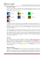
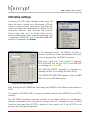
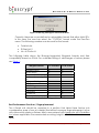
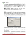
1
Veri-Series Operations Manual V-Prox / V-Flex / V-Pass / V-Smart / V-Station Version 7.50 Document #430-00127-18 ©Copyright 2005, Bioscrypt Inc. All rights reserved. Trademark Disclosures Bioscrypt has made every effort to provide disclosures when using trademarks owned by other companies. Trademarked designations appear throughout this publication. The publisher states that it is using the designations only for editorial purposes, and to the benefit of the trademark owner with no intent to infringe upon that trademark. The following trademarks are found in this manual: • • • • • V-Prox™, V-Flex™, V-Pass™, V-Smart™, V-Station™, MV1100™, MV1200™ and MV-Lite™ are trademarks of Bioscrypt, Inc. Microsoft™, Windows 95™, Windows 98™, Windows NT™, Windows ME™, Windows 2000™, and Windows XP™ are trademarks of Microsoft Corporation. HID™ is a trademark of HID Corporation. MIFARE® is a registered trademark of Philips Electronics N.V. ICLASS™ is a trademark of HID Corporation. Document #430-00127-18 i ©Copyright 2005, Bioscrypt Inc. All rights reserved. Disclaimer The instructions in this document have been carefully checked for accuracy and are presumed to be reliable. Bioscrypt Inc. and its writers assume no responsibility for inaccuracies and reserve the right to modify and revise this document without notice. It is Bioscrypt’s goal to supply accurate and reliable documentation. If you discover a discrepancy in this document, please e-mail your comments to [email protected], or contact Bioscrypt Technical Support at the telephone number listed below. No part of this publication may be placed in a retrieval system, transmitted, or reproduced in any way, including, but not limited to, photograph, photocopy, computer disk or other record, without prior agreement and written permission from: Bioscrypt Inc. 5805 Sepulveda Blvd. Suite 750 Van Nuys, CA 91411 Phone: 818-304-7180 Toll Free: 866-304-7187 Web: http://www.bioscrypt.com Email: [email protected] Document #430-00127-18 ii ©Copyright 2005, Bioscrypt Inc. All rights reserved. Bioscrypt One Year Limited Warranty Policy Bioscrypt warrants to the original consumer purchaser (“Customer”) that new Bioscrypt products will be free from defects in material and workmanship for one year from the date the product was shipped from Bioscrypt. For replacement products the warranty on the replacement unit is the remainder of the warranty on the original product or ninety (90) days, whichever is longer. The Customer is responsible for making any claims for shipment damage (evident or concealed) with the freight carrier. Bioscrypt must be notified within thirty days of shipment of incorrect materials. If a defect is discovered, Bioscrypt's sole obligation shall be to repair or replace the Bioscrypt product(s) at its sole discretion at no charge, provided it is returned to Bioscrypt during the warranty period and is shipped freight and insurance prepaid. Merchandise must be properly packaged to prevent damage during shipping. Before returning a Bioscrypt product, contact Bioscrypt Technical Service to obtain a Return Material Authorization (RMA) number. No product may be returned whether in warranty or out of warranty without first obtaining approval from Bioscrypt. The model number, invoice number, and serial number may be required for warranty service. This warranty shall not apply to any product or any part of a product, which in the judgment of Bioscrypt, has been subjected to misuse, negligence, alteration, accident, improper maintenance, or damage by excessive physical or electrical stresses. Tampering, such as opening the housing of a biometric reader or replacing parts will void this warranty. The warranty is void if the serial number of the Bioscrypt product has been defaced, altered, or removed or if the product has been modified. Repair and replacement parts will be furnished on an exchange basis and may be either reconditioned or new. All replaced parts or products become the property of Bioscrypt. This warranty may also be voided for failure to comply with Bioscrypt’s return policy. The warranty is not applicable to: • • • • • • • Abnormal wear and tear Damage caused during installation Damage caused by the equipment or system with which the biometric reader is used Damage caused by modifications or repairs not made or authorized by Bioscrypt Damage caused by improper packaging Damage caused by lack of ESD protection Merchandise that is determined to be stolen Document #430-00127-18 iii ©Copyright 2005, Bioscrypt Inc. All rights reserved. All Veri-Series units have an operating temperature range of 0°-60° Celsius (32°-140° Fahrenheit). In addition, the Veri-Series product line has a relative humidity operating range of 0-95% non-condensing. Any device used outside that temperature or humidity range requires an enclosure with thermal or humidity control that can maintain a consistent environment within the stated operating ranges. The newest Bioscrypt Veri-Series products are designed to be weather resistant but no sensor technology exists today that can work in all weather environments. If a Bioscrypt Veri-Series product is not used in a completely indoor environment, then a protective enclosure is required to shield the unit from moisture, dust, other contaminants and temperatures outside the stated operating range. Product failures resulting from exposure to the conditions are not covered under the product warranty. For outdoor installations, Bioscrypt does offer an enclosure to protect the device from exposure to moisture, dust, other contaminants and temperatures outside stated operating range. To maintain the Bioscrypt warranty, the Veri-Series unit must be installed in a Bioscrypt certified outdoor enclosure. When used properly, this enclosure will protect Veri-Series devices in most environments, but not all. The Customer is responsible for determining whether the offered enclosure will appropriately shield Veri-Series devices in their specific installation. Product failures resulting from exposure to moisture, dust, other contaminants and temperatures outside stated operating range, even if an enclosure is used, are not covered under the product warranty. This warranty is exclusive and in lieu of all others, whether oral or written, expressed or implied. Bioscrypt specifically disclaims any and all implied warranties, including without limitation, warranties of merchantability and fitness for any particular purpose. No Bioscrypt dealer, agent, or employee is authorized to make any modification, extension or addition to this warranty. Document #430-00127-18 iv ©Copyright 2005, Bioscrypt Inc. All rights reserved. Bioscrypt Return Policy and Procedures Bioscrypt must be notified within thirty days of the date that a defect is discovered. Bioscrypt will then issue a Return Material Authorization (RMA) number which the Customer must include with all correspondence and display on the outside of the shipping container when returning the product. Any products returned later than 30 days after issuance of an RMA may be subject to review as to whether the authorization to return is still warranted. All Bioscrypt products must be shipped freight and insurance prepaid, in the original shipping container or equivalent. A written description of the defect together with a copy of the invoice and the name of the Dealer who sold the Bioscrypt product must be shipped with the product. All defects must be reproducible at Bioscrypt’s location to qualify for this limited warranty. For shipping addresses and return merchandise authorization contact Bioscrypt Technical Support. Warranty repairs do not re-initiate the warranty period. For repaired or replaced products the warranty on the replacement unit is the remainder of the warranty on the original product or 90 days, whichever is longer. All repairs are completed on a First-in, First-out (FIFO) basis. Bioscrypt will return a repaired or replacement product via ground freight and insurance prepaid. If the Customer desires an airfreight or other expedited return shipping method, then they must agree to pay for the expedited shipping. Returned products that are found to be free of defects may be subject to a $150.00 handling fee and will be returned at the Customer’s expense. Billable Repair Policy By shipping product to Bioscrypt using the RMA provided by the Technical Support Department, you are agreeing to the following terms: For all non-warranty repairs or billable repairs, the customer will be responsible for charges associated with parts, labor and shipping/freight to and from the Bioscrypt repair facility. Once the product is evaluated/inspected by a repair technician, Bioscrypt will provide the customer via e-mail with a written estimate of the aforementioned charges. If any discrepancies arise between the final cost and the initial estimate, the customer will be notified. The customer shall approve any estimate for non-warranty repairs or billable repairs and shall pay the estimated charges before the equipment is repaired. In the event Document #430-00127-18 v ©Copyright 2005, Bioscrypt Inc. All rights reserved. the customer fails to either: (a) pay the estimated charges within 60 days of such estimate; or (b) arrange for return of the un-repaired equipment to the customer at customer’s cost, Bioscrypt will consider the equipment abandoned and will dispose of the equipment. 30 Day Return for Credit Bioscrypt is a leading biometric company, specializing in fingerprint and verification systems. We are confident that customers will be pleased with Bioscrypt products. However, if you are not, and you purchased your merchandise directly from Bioscrypt, new products can be returned for credit within the first 30 days under the following conditions: • • • • You have received an RMA from Bioscrypt Technical Support and the item is returned in accordance with the Bioscrypt Return Policy and Procedures. Return Items are accompanied by proof of purchase. All original materials (accessories, manuals, CDs) are returned with the item. The item is in re-sellable condition. If there are any questions regarding resellable condition Bioscrypt will have the final decision as to whether an item can be returned, exchanged, and if a restocking fee will apply. If you did not purchase your product directly from Bioscrypt Inc, please contact your retailer for their return policy. Document #430-00127-18 vi ©Copyright 2005, Bioscrypt Inc. All rights reserved. Notices The Veri-Series line of products has been tested for compliance with all applicable international standards. The resulting approvals are listed below, and are additionally printed on the labeling located on the rear panel of the product. V-Flex FCC, UL294, CSA, cUL, CE V-Prox FCC, UL294, CSA, cUL, CE under R&TTE V-Pass FCC, UL294, CSA, cUL, CE V-Smart FCC, UL294, CSA, cUL, CE under R&TTE V-Station FCC, UL294, CSA, cUL, CE under R&TTE The power supply offered by Bioscrypt is CE and CSA approved and UL listed. For more information on approvals, notices, and declarations of conformance for all Veri-Series products, please see Appendix A and B within the Veri-Series Installation Guide. Important FCC, CE, and R&TTE information is listed there. Document #430-00127-18 vii ©Copyright 2005, Bioscrypt Inc. All rights reserved. Table of Contents Veri-Series Operations Manual ..................................................................................................i V-Prox / V-Flex / V-Pass / V-Smart / V-Station ....................................................................i Version 7.50 .............................................................................................................................i Trademark Disclosures ................................................................................................................i Disclaimer .................................................................................................................................... ii Bioscrypt One Year Limited Warranty Policy......................................................................... iii Bioscrypt Return Policy and Procedures ................................................................................ v Billable Repair Policy............................................................................................................ v 30 Day Return for Credit .....................................................................................................vi Notices ....................................................................................................................................... vii Table of Contents .................................................................................................................... viii Table of Figures ........................................................................................................................ xiii Notes .........................................................................................................................................xvi Introduction ................................................................................................................................ 1 Terminology ................................................................................................................................ 2 About Veri-Series Products....................................................................................................... 3 About the V-Prox.................................................................................................................. 3 About the V-Flex .................................................................................................................. 3 About the V-Pass.................................................................................................................. 3 About the V-Smart ............................................................................................................... 4 About the V-Station............................................................................................................. 4 Veri-Series – Physical Layout* ............................................................................................. 5 Concepts of Operation ............................................................................................................ 7 The V-Prox.............................................................................................................................. 7 The V-Flex .............................................................................................................................. 8 The V-Pass ............................................................................................................................. 8 The Proximity Card ............................................................................................................... 9 User Cards........................................................................................................................ 9 Command Cards ......................................................................................................... 10 Basic System Administration ............................................................................................. 10 Enrollment ...................................................................................................................... 10 Templates ...................................................................................................................... 10 Multiple Readers........................................................................................................... 12 Backing-Up Templates................................................................................................. 12 LEDs ...................................................................................................................................... 13 VeriAdmin Management Software – v5.50 ......................................................................... 15 Concepts of Operation .................................................................................................... 15 Transmit ID / Current Unit............................................................................................. 15 Host, Aux, and Ethernet Ports ..................................................................................... 17 Serial Port Settings and Baud Rates........................................................................... 17 Document #430-00127-18 viii ©Copyright 2005, Bioscrypt Inc. All rights reserved. Installing the Software ....................................................................................................... 18 Running VeriAdmin for the First Time............................................................................... 19 Network Setup and Configuration........................................................................................ 21 Network Setup .................................................................................................................... 21 Network Configuration Manager.................................................................................... 22 Network Tree ................................................................................................................. 23 General Unit Settings.................................................................................................... 25 Unit Status ...................................................................................................................... 25 Advanced Settings ...................................................................................................... 25 Other Options ............................................................................................................... 26 Setting up a Network......................................................................................................... 27 Icons, Commands and Drop Downs .............................................................................. 28 Template Manager ................................................................................................................. 30 Editing Templates............................................................................................................... 30 Quick Enrollment ................................................................................................................ 32 Delete Templates............................................................................................................... 34 Export List ............................................................................................................................. 34 Verify Template .................................................................................................................. 34 Transfer Templates ............................................................................................................. 35 From Unit to PC ............................................................................................................. 35 From Unit to Smart Card .............................................................................................. 36 From PC to Unit ............................................................................................................. 36 From PC to Smart Card ............................................................................................... 37 Unit to Unit...................................................................................................................... 37 Broadcast PC Template.................................................................................................... 38 Edit PC Template ............................................................................................................... 38 Command Card Manager .................................................................................................... 40 Administering Command Cards...................................................................................... 40 Creating Command Cards ........................................................................................ 40 Removing Command Cards ...................................................................................... 40 Using Command Cards .................................................................................................... 41 Enroll Command Card ................................................................................................ 41 Delete Command Card.............................................................................................. 41 Unit Parameters........................................................................................................................ 42 General Tab........................................................................................................................ 42 Communication Tab ......................................................................................................... 43 Network Identification Number.................................................................................. 43 MV1200 Veri-Series Port MODE ................................................................................... 44 Host Port Protocol ......................................................................................................... 44 Host Port and Aux Port Baud Rates ........................................................................... 44 Aux Port Security........................................................................................................... 45 Test Communications .................................................................................................. 46 Wiegand Tab ...................................................................................................................... 46 Document #430-00127-18 ix ©Copyright 2005, Bioscrypt Inc. All rights reserved. Pre-Defined Wiegand Format .................................................................................... 46 Upload Custom Format ............................................................................................... 46 On Success: Alt Site Code .......................................................................................... 47 On Failure: Fail ID Code............................................................................................... 48 On Failure: Fail Site Code ............................................................................................ 48 On Failure: Invert Parity Bits ......................................................................................... 48 Enable INPUT ................................................................................................................. 48 Enable OUTPUT.............................................................................................................. 48 Pulse Width .................................................................................................................... 49 Pulse Interval ................................................................................................................. 49 Wiegand PASS-THRU formats ...................................................................................... 49 Creating USER DEFINED PASS-THRU Format Options ............................................... 50 Biometrics Tab .................................................................................................................... 51 Global Security Threshold............................................................................................ 52 Biometric Verification................................................................................................... 52 Finger Detect (V-Pass and V-Station Searching only) ............................................ 52 Template Security......................................................................................................... 53 Multi-Finger Verification............................................................................................... 53 Password Verification (V-Station only) ...................................................................... 53 Duress Finger Mode...................................................................................................... 53 Verification Action Response Tab ................................................................................... 54 Send Verification Result............................................................................................... 54 Verification Polling Mode............................................................................................ 55 General Purpose I/O Tab.................................................................................................. 55 General Purpose Input ................................................................................................ 56 General Purpose Output............................................................................................. 57 Broadcast Parameters ............................................................................................................ 58 Advanced Enrollment............................................................................................................. 59 LED Table Settings.................................................................................................................... 62 Sensor Configuration............................................................................................................... 63 Veridicom Sensors.............................................................................................................. 63 Authentec Sensors ............................................................................................................. 63 Update Firmware..................................................................................................................... 64 Reset Unit to Factory Defaults ............................................................................................... 70 Template Conversion.............................................................................................................. 71 Verification Action Response ................................................................................................ 72 Wiegand Utilities ...................................................................................................................... 73 Getting Service and Support................................................................................................. 74 Technical Support .............................................................................................................. 74 Customer Service and Sales Support ............................................................................. 74 World Wide Web Site......................................................................................................... 74 Appendix A: Quality and Content ....................................................................................... 75 Section A.1: Basic Biometric Concepts .......................................................................... 75 Document #430-00127-18 x ©Copyright 2005, Bioscrypt Inc. All rights reserved. Biometric Definitions..................................................................................................... 75 Scanning an Image ..................................................................................................... 75 Storing User Templates on the Unit ............................................................................ 76 Section A.2: Proper Finger Placement............................................................................ 76 Common mistakes ....................................................................................................... 77 Image quality................................................................................................................ 77 Image consistency....................................................................................................... 77 Section A.3: Using Quality & Content Scores ................................................................ 78 False Acceptance and False Rejection ................................................................... 78 Quality............................................................................................................................ 79 Content.......................................................................................................................... 80 Content and Quality Summary .................................................................................. 81 Recommended Enrollment Process .......................................................................... 81 Appendix B: Broadcasting for RS-485 Networks.................................................................. 82 Appendix C: Searching vs. One-to-One Templates .......................................................... 84 Appendix D: V-Smart Operations ......................................................................................... 86 Administrator’s Note .......................................................................................................... 86 V-Smart Terminology ......................................................................................................... 87 V-Smart Smart Card Placement ...................................................................................... 87 Section D.1: HOST Mode versus SLAVE Mode Operation ............................................ 88 Section D.2: Transferring a Template to a Smart Card................................................. 89 Section D.3: Enrolling a Template Directly to a Smart Card........................................ 90 Section D.4: Using the Smart Card Manager ................................................................ 90 MIFARE based V-Smart Layout Manager ................................................................. 96 iCLASS based V-Smart Layout Manager .................................................................. 99 Section D.5: Verification Using a Smart Card .............................................................. 101 Section D.6: Using the Smart Card Serial Number as the Template ID.................... 102 MIFARE Serial Number................................................................................................ 102 iCLASS Serial Number................................................................................................. 103 Best Performance Practices / Finger placement ....................................................... 104 Appendix E: Smart Card SiteKey Management............................................................... 106 What is a SiteKey?............................................................................................................ 106 Why do I Need a SiteKey?.............................................................................................. 107 What is the “Default” SiteKey?....................................................................................... 107 Where is the SiteKey Stored?.......................................................................................... 107 What is the Difference Between PRIMARY and SECONDARY SiteKeys? ................. 107 How do I Initially Set a SiteKey for V-Smarts at My Installation?................................ 107 How do I Set the SiteKey on Individual Smart Cards?................................................ 109 How do I Change the SiteKey if I Already Have a User Base of Previously Created V-Smart Smart Cards? ..................................................................................................... 110 What Happens if I FORGET My SiteKey? ....................................................................... 111 What Happens if Someone Else Learns My Installation’s SiteKey?........................... 111 What is the 1-Way Hashing Function Option In VeriAdmin for SiteKeys? ................ 112 Document #430-00127-18 xi ©Copyright 2005, Bioscrypt Inc. All rights reserved. How does iCLASS differ from MIFARE as it pertains to SiteKeys?............................... 112 Appendix F: V-Station Operations ...................................................................................... 113 Section F.1: Using the V-Station Manager.................................................................... 113 Clock ............................................................................................................................ 113 Ethernet........................................................................................................................ 114 Biometric Schedules................................................................................................... 115 Menus........................................................................................................................... 117 Access Schedules....................................................................................................... 118 Holiday Schedules...................................................................................................... 120 Transaction Log .......................................................................................................... 121 Section F.2: VeriAdmin vs. Keypad Configuration...................................................... 123 Section F.3: V-Station Security and Admin Levels....................................................... 123 Section F.4 – Broadcasting to V-Stations ...................................................................... 124 Bioscrypt Contact Information ............................................................................................ 125 Document #430-00127-18 xii ©Copyright 2005, Bioscrypt Inc. All rights reserved. Table of Figures Figure 1: Top View ..................................................................................................................... 5 Figure 2: Bottom View ............................................................................................................... 5 Figure 3: Bottom Panel - Closed.............................................................................................. 5 Figure 4: Bottom Panel - Open ................................................................................................ 5 Figure 5: Veri-Series Unit and Mounting Plate ....................................................................... 6 Figure 6: Proximity Card............................................................................................................ 9 Figure 7: Template ID Numbers ............................................................................................. 11 Figure 8: Saving Templates to PC.......................................................................................... 13 Figure 9: Transmit ID / Current Unit Drop-down................................................................... 16 Figure 10: Broadcast Transmit ID in Drop-down .................................................................. 16 Figure 11: No Response Message ......................................................................................... 16 Figure 12: VeriAdmin desktop icon....................................................................................... 18 Figure 13: VeriAdmin Welcome Message (A) ..................................................................... 19 Figure 14: VeriAdmin Welcome Message (B)...................................................................... 20 Figure 15: Network Setup dialog. .......................................................................................... 22 Figure 16: Network Configuration dialog............................................................................. 23 Figure 17: Advanced Options ............................................................................................... 26 Figure 18: Test Communication Settings .............................................................................. 26 Figure 19: Template Manager Dialog. ................................................................................. 30 Figure 20: Template Viewer ................................................................................................... 31 Figure 21: Access Schedule Selection.................................................................................. 32 Figure 22: Quick Enrollment Screen ...................................................................................... 33 Figure 23: Download Template(s) to PC .............................................................................. 35 Figure 24: Download Template(s) to Smart Card............................................................... 36 Figure 25: Download Template(s) to Smart Card............................................................... 36 Figure 26: Download Template(s) to Smart Card............................................................... 36 Figure 27: Upload Template(s) to Unit .................................................................................. 37 Figure 28: Transfer Templates from Unit to Unit ................................................................... 38 Figure 29: Template Viewer ................................................................................................... 39 Figure 30: Command Card Manager .................................................................................. 40 Figure 31: Unit Parameters Dialog – General Tab............................................................... 42 Figure 32: Unit Parameters Dialog – Communication Tab ................................................ 43 Figure 33: Unit Parameters Dialog – Wiegand Tab............................................................. 46 Figure 34: Unit Parameters Dialog – Biometrics Tab ........................................................... 52 Figure 35: Unit Parameters Dialog – Verification Response Tab....................................... 54 Figure 36: Unit Parameters Dialog – General Purpose I/O ................................................ 56 Figure 37: Broadcast Parameters Window .......................................................................... 58 Figure 38: The Advanced Enrollment Screen ...................................................................... 59 Figure 39: Advanced Enrollment – Finger Selection .......................................................... 60 Figure 40: Advanced Enrollment – Recommended Choice ............................................ 60 Document #430-00127-18 xiii ©Copyright 2005, Bioscrypt Inc. All rights reserved. Figure 41: Advanced Enrollment – Finger Selection Option ............................................. 61 Figure 42: Advanced Enrollment – OVERRIDE Recommended Choice ......................... 61 Figure 43: LED Table Settings Menu ...................................................................................... 62 Figure 44: LED Table Settings.................................................................................................. 62 Figure 45: Sensor Configuration Menu ................................................................................. 63 Figure 46: Sensor Configuration............................................................................................. 63 Figure 47: Update Firmware Menu ....................................................................................... 64 Figure 48: Bioscrypt Firmware Update Wizard..................................................................... 64 Figure 49: Firmware Update Wizard – Step 1....................................................................... 65 Figure 50: Firmware Update Wizard – Step 3....................................................................... 66 Figure 51: Firmware Update Wizard – Step 2....................................................................... 67 Figure 52: Firmware Update Wizard – Step 4....................................................................... 68 Figure 53: Firmware Update Wizard – Verifying Successful Update ................................ 68 Figure 54: Reset Unit to Factory Defaults Menu .................................................................. 70 Figure 55: Parameters are grouped into like sections........................................................ 70 Figure 56: Template Conversion Menu ................................................................................ 71 Figure 57: Template Conversion Dialog ............................................................................... 71 Figure 58: Verification Action Response Menu ................................................................... 72 Figure 59: Wiegand Utilities Menu ......................................................................................... 73 Figure 60: Wiegand Utilities dialog ........................................................................................ 73 Figure 61: Low and High Quality Fingerprints ...................................................................... 79 Figure 62: High and Low Content Fingerprints .................................................................... 80 Figure 63: Proper Smart Card Placement............................................................................ 88 Figure 64: Template Manager dialog................................................................................... 89 Figure 65: The Template Viewer ............................................................................................ 90 Figure 66: The Smart Card Manager .................................................................................... 91 Figure 67: VeriAdmin Notification About Wiegand String ................................................. 92 Figure 68: Smart Card Security Settings................................................................................ 95 Figure 69: Smart Card Layout Manager (MIFARE).............................................................. 96 Figure 70: Smart Card Layout Manager (iCLASS)............................................................... 99 Figure 71: Quick Enrollment "Smart Card SN" button ....................................................... 102 Figure 72: Warning message for less than 32 bit ID .......................................................... 103 Figure 73: Warning message for less than 64-bit ID .......................................................... 104 Figure 74: Smart Card Security Settings.............................................................................. 108 Figure 75: VeriAdmin Warning on SiteKey Change.......................................................... 109 Figure 76: VeriAdmin Security Settings ............................................................................... 110 Figure 77: V-Station Manager.............................................................................................. 113 Figure 78: V-Station Manager - Ethernet Tab .................................................................... 115 Figure 79: V-Station Manager - Biometric Schedules Tab ............................................... 116 Figure 80: One-Day Biometric Scheduling Dialog ............................................................ 116 Figure 81: V-Station Manager - Menus Tab ....................................................................... 117 Figure 82: V-Station Manager - Access Schedules Tab................................................... 119 Figure 83: V-Station Manager - Holiday Schedules Tab .................................................. 121 Document #430-00127-18 xiv ©Copyright 2005, Bioscrypt Inc. All rights reserved. Figure 84: V-Station Transaction Log .................................................................................. 122 Document #430-00127-18 xv ©Copyright 2005, Bioscrypt Inc. All rights reserved. Notes Document #430-00127-18 xvi ©Copyright 2005, Bioscrypt Inc. All rights reserved. INTRODUCTION Introduction Bioscrypt, the leader in fingerprint identification and verification systems, presents the Veri-Series Fingerprint Verification System. Technology by Bioscrypt has been applied in various unique applications including Access Security, Time and Attendance, Political Polling, Computer Logon, and other applications where an individual must be clearly identified as being solely responsible for specific actions. Bioscrypt (formerly BiometricID) was founded in 1996 with a mission to provide fingerprint recognition technology with the highest degree of accuracy at a reasonable cost while still being easy to use. Bioscrypt has successfully migrated technology once found only in government or military applications toward private industry and small businesses around the globe. It has been known for years that each person has unique fingerprints. Using fingerprints as a means of identification ensures a unique identifier for each tracked user, and protects users from the vulnerabilities associated with lost keys or identification cards. After installing Bioscrypt’s product in your application, your company will be able to accurately identify, track, and automatically act according to each individual’s identification and permissions. Document #430-00127-18 1 ©Copyright 2005, Bioscrypt Inc. All rights reserved. TERMINOLOGY Terminology This document is intended for use with Bioscrypt’s Veri-Series product line, including the V-Prox, V-Flex, V-Pass, V-Smart, and V-Station hardware products. These five products share many common aspects. When this manual refers to the ‘V-Prox,’ unless specifically stated otherwise, the entire Veri-Series is being described. This document also refers to Bioscrypt’s MV1100 and MV1200. The MV1100/MV1200 is the internal hardware biometric engine that is the core of all Veri-Series products. This circuit board contains the DSP processor, support hardware, and interface to a variety of fingerprint sensors. The MV1100/MV1200 also contains firmware, the low level software that controls the mathematical instructions that perform the actual fingerprint enrollment and verification processes. This document describes a particular version of firmware (see title page). Please ensure that the version of firmware found on your Veri-Series reader(s) matches this version. If the version does not match this document, please contact Bioscrypt Technical Support and ask for the manual corresponding to your version of firmware. Several Veri-Series products contain a component referred to within this document as the ESI (External Storage Interface). It is a hardware component coupled to a MIFARE or an iCLASS smart card reader (or possibly another device in the future). The ESI also contains firmware that may be upgraded through the VeriAdmin software. This component stores many variables associated with smart card usage, such as SiteKeys (passwords), card layouts, and other settings. It handles all communication with the reader, and is reader hardware dependent (i.e., there is one version for MIFARE (a.k.a. Gemplus) readers and one version for HID iCLASS readers). The V-Station product line also introduces two new components mentioned in this document: the Communication Manager (CM) and the Kit. These are both microcontrollers found within the V-Station and each one contains firmware. The CM firmware version will always be in alignment with the MV1200 firmware version because these components work closely together. The CM is responsible for routing communications internally within the V-Station, controlling the real-time clock, and managing the LCD menus. The Kit controls the keypad, buzzer tones, and LCD contrast. Document #430-00127-18 2 ©Copyright 2005, Bioscrypt Inc. All rights reserved. ABOUT VERI-SERIES PRODUCTS About Veri-Series Products About the V-Prox Bioscrypt’s V-Prox combines patented fingerprint verification technology with an industry-standard proximity card reader in a mullion-mountable case. This ensures greater security for the card issuer and the card user. The requirement that the fingerprint of the person seeking entry match the identity of the cardholder eliminates access via lost or stolen proximity cards. Suitable for both stand-alone and network use, the system works with existing 26-bit proximity card infrastructures. The unit operates in conjunction with administration software hosted on a PC. Installed users simply present their identification cards when entering the secure area and then touch a finger to the recessed area on top of the unit. The system validates their fingerprint against a previously enrolled template stored in flash memory. The V-Prox system provides security features that can minimize fraud and can tolerate changes to the user’s finger like scarring or swelling. The V-Prox returns accurate pass and fail decisions in 99.99% of all cases. Each V-Prox unit stores thousands of fingerprint templates in non-volatile memory. Response time is less than five seconds for fingerprint enrollment and less than 1.5 seconds for fingerprint verification. The system is compact, versatile, and configured to allow standalone, PC-connected, or multiple-unit operation. About the V-Flex V-Flex includes all features found in the V-Prox except it does not include the internal proximity card reader. External connections to Wiegand devices still exist and allow the V-Flex to be added to installations that already have supported Wiegand devices installed. Whereas the V-Prox can operate as a standalone device, the VFlex requires an external device (such as an external Wiegand reader or PC) that initiates enrollment, verification, and template administration activities. About the V-Pass Bioscrypt’s V-Pass is similar in construction to the V-Flex but incorporates an entirely different biometric algorithm. Whereas the V-Prox and V-Flex will perform a 1:1 matching verification where an ID number is required, the V-Pass performs 1:M identification utilizing a searching algorithm that compares the user’s fingerprint with every stored template to find a potential match. This ability eliminates the need to provide the unit with an ID number to verify, as with a proximity card. The users simply place their finger on the sensor, and a PASS / FAIL is determined. No external or Document #430-00127-18 3 ©Copyright 2005, Bioscrypt Inc. All rights reserved. ABOUT VERI-SERIES PRODUCTS internal Wiegand input device is required. Once the fingerprints are enrolled on the unit, the V-Pass can operate in a standalone mode. A V-Pass can still be connected to Wiegand Input devices similar to a V-Flex. If a recognized Wiegand signal is received containing a valid ID number, the V-Pass will perform a simple 1:1 verification and not a searching operation. NOTE: the V-Pass fingerprint templates are different from the smaller 1:1 fingerprint templates. Please see Appendix C for further details. About the V-Smart Bioscrypt’s V-Smart provides all the capabilities of the V-Flex and includes an internal smart card reader. Fingerprint templates are securely stored on a smart card rather than on the reader and carried by the employee or user. This allows for an unlimited population of users. The smart card is presented to the V-Smart and the template is read from the smart card and verified against the employee’s live image. Storing the template on the smart card allows the V-Smart to have an unlimited user base and removes the need for a physically wired network. Wiegand communication formats of up to 64 bits can also be stored on the smart card and optionally used with a Wiegand device. About the V-Station Bioscrypt’s V-Station is the newest and most versatile Veri-Series product. It is the first completely stand-alone version of the Veri-Series product line with an integrated keypad and LCD display. Most actions can be performed right from the console, thereby freeing users from having to administer the device from a PC. The standard version stores more than 3000 templates based on IDs entered on the keypad, but versions are available which include an enclosed proximity or smart card reader. A searching version is also available. In addition, this is the first product to offer built-in Ethernet support*, and is by far the most flexible of the available devices. *Ethernet is fully supported in firmware versions 7.10 and above. Document #430-00127-18 4 ©Copyright 2005, Bioscrypt Inc. All rights reserved. ABOUT VERI-SERIES PRODUCTS Veri-Series – Physical Layout* Figure 1: Top View Figure 2: Bottom View Figure 3: Bottom Panel - Closed Document #430-00127-18 Figure 4: Bottom Panel - Open 5 ©Copyright 2005, Bioscrypt Inc. All rights reserved. ABOUT VERI-SERIES PRODUCTS Figure 5: Veri-Series Unit and Mounting Plate *NOTE: Older MV1100-based Veri-Series readers have a different plastic housing and appear much differently than Figures 1 – 5; however, they contain the same basic components. Also, the V-Station models look substantially different than Figures 1 – 5, but still contain essentially the same components. For additional information on installing and connecting your Veri-Series unit, please refer to the Veri-Series Installation Guide. Document #430-00127-18 6 ©Copyright 2005, Bioscrypt Inc. All rights reserved. CONCEPTS OF OPERATION Concepts of Operation The V-Prox The V-Prox integrates an industry-standard proximity card reader with Bioscrypt’s MV1200 fingerprint verification technology. A typical operation is described below. • • • • • • • • A user waves the proximity card near the front of the V-Prox. The ID number is read from the internal proximity card reader. The ID is transferred to the V-Prox. o If the ID is invalid, the LED on the top of the V-Prox will glow red. o If the ID presents a valid previously enrolled template, the LED on the top of the reader will glow amber; indicating the user should place their finger on the sensor on the top of the reader. The User should place the correct finger on the scanner using the Bioscrypt Ridge-Lock. The amber light will turn off, signaling the finger can be removed. The scanned image is compared with the data that is stored under the ID number in the memory of the V-Prox. o If the verification is positive, the top LED will glow green and the unit will emit an audible beep. o If the authentication fails, the LED will glow red and no beep will be generated. When authentication is successful a Wiegand string that contains the site code and ID number read from the proximity card is sent out for use by a standard door controller. Optionally, the V-Prox can be configured to send out a pre-determined “failure” string whenever an unsuccessful verification occurs. The V-Prox has several serial communication options. It is equipped with a RS-485 DB15 port, a RS-232 DB15 port and the RS-232 RJ11 bottom port. Of the three, only two may be active at a time. The MV1200 Veri-Series Port MODE parameter designates the two active ports and assigns one as Host and the other as Auxiliary. The RS-232 RJ-11 port is hidden under a door on the bottom of the V-Prox. This door is held shut with a security locking screw. The V-Prox can be used as a stand-alone reader or multiple units can be configured on a RS-485 network. The manner in which the V-Prox is installed will determine which communications settings are most convenient. Administrative functions common to any installation will be required. Users must be “enrolled” into the system (that is, associate a user’s fingerprint data with a specific proximity card ID number). Also, this data must be distributed to all other readers in the installation. The VeriAdmin Document #430-00127-18 7 ©Copyright 2005, Bioscrypt Inc. All rights reserved. CONCEPTS OF OPERATION Management Software is provided for this purpose. The V-Flex The V-Flex is similar to the V-Prox except that an external Wiegand device is used. A typical operation is described below. • • • • • • • • A user initiates the action with the external Wiegand device. The ID number is read from the external reader. The ID is transferred to the V-Flex. o If the ID is invalid, the LED on the top of the V-Flex will glow red. o If the ID presents a valid previously enrolled template, the LED on the top of the reader will glow amber; indicating the user should place their finger on the sensor on the top of the reader. The User should place the correct finger on the scanner using the Bioscrypt Ridge-Lock. The amber light will turn off, signaling the finger can be removed. The scanned image is compared with the data that is stored under the ID number in the memory of the V-Flex. o If the verification is positive, the top LED will glow green and the unit will emit an audible beep. o If the authentication fails, the LED will glow red and no beep will be generated. When authentication is successful a Wiegand string that contains the site code and ID number read from the external Wiegand device is sent out for use by a standard door controller. Optionally, the V-Flex can be configured to send out a pre-determined “failure” string whenever an unsuccessful verification occurs. The V-Flex provides the same serial communication options as the V-Prox. Also, it is packaged into identical housing as the V-Prox, providing a pigtail connection in the back and a RJ-11 RS-232 port at the bottom of the unit. Configuration and administrative requirements are identical to the V-Prox and VeriAdmin Management Software can also be used for this purpose. The V-Pass The V-Pass is similar to the V-Prox and V-Flex, but no Wiegand input device is required. The V-Pass will automatically detect when a finger is placed on the sensor, compare that fingerprint with all currently enrolled fingerprint templates and determine if there is a match. A typical operation is described below. • • The V-Pass top LED is amber to indicate it is ready for a finger. A user initiates the action by placing their finger on the fingerprint sensor. Document #430-00127-18 8 ©Copyright 2005, Bioscrypt Inc. All rights reserved. CONCEPTS • • • • • OF OPERATION The User should place the correct finger on the scanner using the Bioscrypt Ridge-Lock. The V-Pass will recognize that a finger has been placed and will take an image of that finger’s print. The amber light will turn off, signaling that the image has been scanned and the finger can be removed. The scanned image is compared with ALL enrolled templates in the memory of the V-Pass (maximum of 500). o If the verification is positive, the top LED will glow green and the unit will emit an audible beep. o If the authentication fails, the LED will glow red and no beep will be generated. When authentication is successful a Wiegand string can optionally be sent out for use by a standard door controller. As with the V-Flex, the V-Pass provides the same serial communication options as the V-Prox and is packaged into identical housing, providing a pigtail connection in the back and a RJ-11 RS-232 port at the bottom of the unit. Configuration and administrative requirements are similar to the V-Prox and VeriAdmin Management Software can also be used for this purpose. The Proximity Card Figure 6: Proximity Card NOTE: Some proximity cards do not have numbers printed on them. There are three types of proximity cards split into two basic categories: • • • User Cards Enroll Command Cards Delete Command Cards User Cards All Veri-Series units (with embedded proximity card capability) can be Document #430-00127-18 9 ©Copyright 2005, Bioscrypt Inc. All rights reserved. CONCEPTS OF OPERATION programmed to use a given card ID number as a standard “user card.” The majority of cards will be of this type. Command Cards Command Cards can be created to add and remove users from a Veri-Series reader without using the PC based administrative software. These can be useful for creating and removing temporary visitor’s badges or administering the system when the PC is down or unavailable. There are two types of Command Cards: • • Enroll Command Cards Delete Command Cards NOTE: The command Administration Software. cards must be created using the VeriAdmin Once a card has been designated as one of the three types, it will remain that type unless it is deleted and re-enrolled (see Editing Templates). Basic System Administration Enrollment New users are entered into the system through the process of “enrollment.” During this procedure, the user’s fingerprint is scanned and a fingerprint template is generated. A template is a collection of user information including the fingerprint data. The information includes: • • • • • • • • • ID Number (contact Tech Support for valid range of values) Extended ID Number (Optional) Index Number (0 – 255) User Name (optional) User Type (User, Admin, etc.); (Optional) User Finger Identifier (optional) 1:1 Template Security Threshold Password (optional) A mathematical model of the fingerprint ridge pattern Templates Every template on a Veri-Series unit has a unique identification tag consisting of a Template ID and a Template Index. Each time a fingerprint is enrolled, a new template is generated using the number from the proximity card or PC as the Document #430-00127-18 10 ©Copyright 2005, Bioscrypt Inc. All rights reserved. CONCEPTS OF OPERATION Template ID number. Unless specifically defined, the Veri-Series product will automatically assign a unique index value to each template. NOTE: The Template Index number will be the lowest value available for that ID number unless specially defined using an external PC application. Each template ID is usually considered a template belonging to a different individual while the Index number is usually used to differentiate different templates for the same individual. Figure 7: Template ID Numbers There are several other attributes of a template that are important for an Administrator to understand. The following template options should be fully understood before using them. • • • • 1:1 Template Security Threshold – Each template can be assigned a specific security threshold from Very Low to Very High, None, or Password Only. For security levels Very Low through Very High, please see Appendix A: Quality and Content. A security level of None will allow any finger to pass and is only recommended as a last resort for fingers difficult to enroll. A security level of Password-Only is a better option for users with troublesome fingerprints on V-Station units. Note that the template MUST have a non-zero password or else templates with this security level will always pass verification without the V-Station asking for a password. Beware also that this security setting is treated the same as “None” when used on a non-V-Station unit because only a V-Station has a keypad for the user to type in their password. Password – When a V-Station unit has the password mode enabled (see the Unit Parameters section), each template can have an extra level of security by requiring a password in addition to (or instead of) a finger. The password field is actually a number (more like a PIN really) and must be non-zero. A zero password is treated like no password. User Type – This indicates whether the user has special privileges, such as an Administrator, Enroller, etc. User Types “V-Station Admin ID” or “VStation Enroll ID” are intended only for use on V-Stations while “Prox Enroll ID” and “Prox Delete ID” types are intended for installations using proximity readers. Basic users should be assigned to the “User ID” type. Finger/Duress Finger – The finger enrolled for the template should always be specified. Designating the finger as a Duress Finger is a special case Document #430-00127-18 11 ©Copyright 2005, Bioscrypt Inc. All rights reserved. CONCEPTS • • OF OPERATION making the template a “Duress Template”. When Duress Mode is enabled (see Unit Parameters section) and this particular finger verifies, a duress condition is recognized by the device and special action is taken. Access Schedule/Observe Holidays – On V-Station units, each template can be assigned an access schedule which dictates when the user will be granted access as well as whether the user should be granted access during holidays. Please see Editing Templates and Section F.1: Using the V-Station Manager for more details. Extended ID – Some Wiegand formats utilize IDs greater than 32 bits in length, which are stored in the “Extended ID” field (for a list of valid ID values, please refer to Table1.) As distinct from pre-6.0 VeriAdmin, this field can be used at the same time as the Password and Employee ID fields. Please see Appendix A: Quality and Content for a technical description of what constitutes a good enrollment. A quality enrollment will ensure peak performance from the Bioscrypt fingerprint recognition algorithm. Multiple Readers If your installation includes multiple Veri-Series readers that are used by a common population of users, you will need to distribute the fingerprint template of each user to all the readers. NOTE: It is recommended that you designate one Bioscrypt Unit as the “administration reader” and enroll all new users on this unit. After a new user is enrolled on the administration unit, the template can be copied to the other readers. If the units are networked, you can broadcast the new template to the other readers over RS-485 lines or an Ethernet network (for V-Stations) using the VeriAdmin Management Software. If the readers are not interconnected, a laptop can be used to download the templates from the administration reader and then upload them to each reader through its Aux Port. Backing-Up Templates Templates can be “backed-up” by downloading them to a PC. On the PC, templates will either be “*.tem” for 1:1 verification records or “*.tms” for the larger searching templates (see Appendix C: Searching vs. One-to-One Templates). The name of the file is derived from the Template ID number and the Template Index number. For example, the first file (10_0.tem) in Figure 8 below is of Template ID 10 and Template Index 0 (referred to as Template 10-0). Document #430-00127-18 12 ©Copyright 2005, Bioscrypt Inc. All rights reserved. CONCEPTS OF OPERATION Figure 8: Saving Templates to PC NOTE: When the template is uploaded from the PC to a Veri-Series reader, the Template ID number and Index number is taken from data within the file, not from the file name. Therefore, even if you change the name of the file on your PC, the Template ID and index will remain the same. Please use the VeriAdmin Management Software to modify Template ID numbers. LEDs The top LED of all Veri-Series units (see Figure 1) can illuminate in various colors and patterns. Generally, a steady color indicates a normal state while a blinking LED usually indicates a special state, such as expecting action from the user. Green is generally used to indicate a positive response while red indicates a negative response. Although configurable by the user, all units ship from the factory with the default LED configuration described below. To configure alternate LED behavior, please see the section describing the LED Table Settings. • • • • • • Steady Amber: The unit is requesting that a finger be placed on the sensor. This may be for verification or for enrollment. The user may remove the finger when the light goes out. Blinking Amber: The unit is requesting a proximity card be waved for enrollment into the reader. The blinking amber light is seen when an Enroll Command Card is used to add a new user to the reader. Steady Green: The unit is indicating the successful completion of a verification, enrollment, or template deletion. A steady green light is accompanied by an audible beep. Blinking Green: The unit has multi-finger mode enabled and is waiting for a second finger to verify. Steady Red: The unit is indicating the current operation has failed. Blinking Red: The unit is requesting a proximity card be waved. The card ID number will be deleted from the reader. The blinking red light is seen when a Delete Command Card is used to remove an existing ID from the reader. Document #430-00127-18 13 ©Copyright 2005, Bioscrypt Inc. All rights reserved. CONCEPTS • OF OPERATION Other: The unit may blink alternating colors when in the middle of a “Step” firmware update. Do not touch the unit during this time. Document #430-00127-18 14 ©Copyright 2005, Bioscrypt Inc. All rights reserved. VERIADMIN MANAGEMENT SOFTWARE – V 5.50 VeriAdmin Management Software – v5.50 The VeriAdmin Management Software is designed to run on Windows-based PC platforms and communicate with Bioscrypt’s MV1100 and MV1200 based fingerprint recognition devices. Although oriented more towards the Veri-Series products, the application works well with any MV1100 or MV1200 device. In this documentation, the terms “unit” and “reader” are used as a generic term to refer to any of these devices. The VeriAdmin Management Software does NOT support Bioscrypt’s VeriPrint V2000 or V2100 fingerprint recognition terminal. Please contact Bioscrypt Technical Support for software that supports this product. Use the VeriAdmin Management software to perform the following functions: • • • • • • • • • Manage the network of Veri-Series readers Enroll new user fingerprint templates. Edit user templates. Distribute the user templates from the administration reader or PC to other Bioscrypt readers in the installation. Create “command cards,” proximity cards with the privilege to enroll or delete other user cards (for products which contain proximity card readers). Adjust the parameters (baud rate, security level, port configuration, Wiegand settings, etc) of individual units, or of all readers connected on a network. Configure the layout and operation of Smart Cards (for products which contain smart card readers). Configure the operation of the V-Station’s LCD, menus, schedules, etc, and view, download, and delete the V-Station transaction log. Perform firmware updates. NOTE: The recommended operating system for use with the VeriAdmin Management Software is Windows 2000™, Windows XP™, or Windows NT™ 4.0 (Service Pack 3 or greater). Operation is possible on Windows 98™ or ME™, however occasional communication packets can be dropped when multiple applications are running in the background. Running VeriAdmin on Windows 95™ is no longer supported. Concepts of Operation Transmit ID / Current Unit On the tool bar of the VeriAdmin software, there is a drop-down list containing a list of available units (see Figure 9 below). There is a small icon representing the reader, its ID number, and its name. This is the reader with which the software is currently communicating. For this reason, each reader must be Document #430-00127-18 15 ©Copyright 2005, Bioscrypt Inc. All rights reserved. VERIADMIN MANAGEMENT SOFTWARE – V 5.50 assigned a Network ID, even if your installation consists of a single unit (the default setting is 0). Assigning a name is optional. Keep in mind that a unit’s Network ID is not the same as the Transmit ID in VeriAdmin. Figure 9: Transmit ID / Current Unit Drop-down A special transmit ID number, “-1”, is assigned as a broadcast ID. All units on the current COMM Port or Ethernet network will respond to this broadcast ID. For functions labeled “broadcast” the software uses the broadcast ID and all readers on the network will accept these commands. For each port defined, VeriAdmin will list a corresponding Broadcast option in the drop-down (see Figure 10 below). Using Broadcast commands is only recommended for advanced users. (See Appendix B: Broadcasting for RS-485 Networks for further understanding of the benefits and issues with broadcasting commands.) Figure 10: Broadcast Transmit ID in Drop-down If VeriAdmin has difficulty communicating with the currently selected device, an error message will be displayed (see Figure 11 below). There are several reasons that could cause this. The most common are: • • • • • • Power has not been supplied or has been incorrectly applied to the unit The unit is not connected to the PC via one of the ports The Transmit ID does not match the unit’s Network ID The VeriAdmin’s baud rate setting does not match the unit’s baud rate Multiple units on a network have been assigned the same Network ID For Ethernet, the IP address may be incorrect, different from the IP address on the unit, or conflict with another device on the network Figure 11: No Response Message Document #430-00127-18 16 ©Copyright 2005, Bioscrypt Inc. All rights reserved. VERIADMIN MANAGEMENT SOFTWARE – V 5.50 Two units on the network cannot have the same ID is because both units would respond to commands sent to that ID. This causes the information packets to “collide” and become jumbled, resulting in communication errors. This applies only to a RS-485 network and not to an Ethernet network. Host, Aux, and Ethernet Ports Bioscrypt readers “talk” to the VeriAdmin software through either the Host port, the Auxiliary (Aux) port, or the Ethernet port (V-Station only). All units have two RS-232 ports (one accessible at the rear of the device and the other accessible through the bottom RJ-11 port). All units also have one RS-485 port. The communication parameter settings will allow the user to designate one port as host and the other as an auxiliary port. Different wires are used for RS-485 versus RS-232. Please refer to the Veri-Series Installation Guide (included on the Installation CD) for details. The Ethernet port on a V-Station is accessed at the back of the unit with a standard Ethernet cable. Note that communication via the Ethernet port on V-Stations require firmware versions 7.10 and above. VeriAdmin 5.10 or later is required for administration. Serial Port Settings and Baud Rates Once the reader(s) have been connected to the PC, the next step is to configure VeriAdmin to recognize which readers are connected to which ports on the PC. As usual, the serial ports on the host PC are designated as COM1, COM2, etc. You may connect up to 31 Veri-Series readers to each COMM line (using RS485). Up to 254 readers may be connected on one Ethernet network (however more can be added to another network and bridged). You must indicate which COM or Ethernet ports you wish to use. This is accomplished using the Network Setup. Additionally, your Bioscrypt network must be defined using the Network Configuration Manager. These dialogs are new in VeriAdmin version 5.00 and above. They replace the older configuration file scheme; it is no longer necessary to maintain the “UNITIDS.DAT” file. In addition the baud rate may be set on each reader. It is essential that the baud rate selected in the VeriAdmin Network Setup match the baud rate setting on the reader and that all readers on the network are set to the same baud rate. The following settings are the factory defaults: A V-Prox / V-Flex / V-Pass should arrive with these settings in place: Document #430-00127-18 17 ©Copyright 2005, Bioscrypt Inc. All rights reserved. VERIADMIN MANAGEMENT SOFTWARE – • • • • Network ID: Port Mode: Host Port baud rate: Aux Port baud rate: V 5.50 0 Mode 1 (Host RS-485 / Aux RS-232 (RJ11)) 9600 baud 57600 baud A V-Smart should arrive with these settings in place: • • • • Network ID: Port Mode: Host Port baud rate: Aux Port baud rate: 0 Mode 0 (Host RS-232 / Aux RS-232 (RJ11)) 57600 baud 57600 baud A V-Station should arrive with these settings in place: • • • • • • Network ID: Port Mode: Host Port protocol: Host Port baud rate: Aux Port baud rate: IP Address: 0 N/A (switch in rear defaults to RS-232 for Host) RS-232 57600 baud 57600 baud 0.0.0.0 Installing the Software To install the software, run the setup.exe file on the VeriAdmin Management CD. You may accept the default path or choose an alternate directory in which to install the software. The default path is C:\Program Files\Bioscrypt\VeriAdmin. Like most Windows based installations, you will step through a number of windows which will request basic installation information such as file name and directory location. It is recommended that the default settings be used. Note that if you are installing over an older version of Veri-Admin, the setup application will first require that you remove the older version. After this step you can proceed with a normal installation. This will not remove any backed up template or network configuration files. Once the installation is complete, a shortcut icon for the Administration Software will appear on your desktop. Figure 12: VeriAdmin desktop icon Beware of deleting or moving the installed files to other locations on the disk, Document #430-00127-18 18 ©Copyright 2005, Bioscrypt Inc. All rights reserved. VERIADMIN MANAGEMENT SOFTWARE – V 5.50 changing their attributes, or altering the Window’s registry settings as this will negatively impact the operation of the software and may cause it to fail. Running VeriAdmin for the First Time Once the installation is complete, VeriAdmin may be run by clicking on the desktop icon, or from the Start menu under ProgramsÆBioscryptÆVeriAdmin. You will see one of two possible welcome screens. If you installed VeriAdmin over an older version, you may see the dialog shown below (Figure 13). Figure 13: VeriAdmin Welcome Message (A) If you see this dialog, it means VeriAdmin has found the old network configuration file (UNITIDS.DAT). As of version 5.00, VeriAdmin handles all network configurations internally; there is no need to manually edit any files. However, VeriAdmin will take advantage of your previous work and import this file for you if you so desire. Selecting this option will bring up the Network Configuration Manager (skip ahead to this section). For customers installing VeriAdmin for the first time, you will see a different welcome message (Figure 14). Document #430-00127-18 19 ©Copyright 2005, Bioscrypt Inc. All rights reserved. VERIADMIN MANAGEMENT SOFTWARE – V 5.50 Figure 14: VeriAdmin Welcome Message (B) Document #430-00127-18 20 ©Copyright 2005, Bioscrypt Inc. All rights reserved. NETWORK SETUP AND CONFIGURATION Network Setup and Configuration Network Setup After dismissing the Welcome dialog, the Network Setup dialog will appear (Figure 15). This screen is used to select which serial ports and Ethernet settings should be used by VeriAdmin. By default all available COM ports will be checked, with baud rates set to 57600. This screen allows you to select up to 20 COM ports, from 1 to 50. Duplicate COM ports are not allowed. The “Auto” column of checkboxes indicates whether VeriAdmin should automatically try all baud rates when establishing communication with a unit. This is a convenient option; however, it can cause VeriAdmin to take longer to connect to a reader. If you are certain of the baud rate you plan to use, uncheck the “Auto” box. Even with this box checked, one should select a proper baud rate from the drop-down; this will be used for broadcasting. The TCP options should generally not be changed, and the network administrator should supply the subnet mask. Document #430-00127-18 21 ©Copyright 2005, Bioscrypt Inc. All rights reserved. NETWORK SETUP AND CONFIGURATION Figure 15: Network Setup dialog. Network Configuration Manager After selecting which serial ports to use, the Network Configuration dialog will present itself (Figure 16). This menu is normally accessed via the network icon on the toolbar. Document #430-00127-18 22 ©Copyright 2005, Bioscrypt Inc. All rights reserved. NETWORK SETUP AND CONFIGURATION Figure 16: Network Configuration dialog This dialog will be the primary tool used to configure your Bioscrypt network. The left portion of the dialog shows your network in a tree hierarchy, with each unit hanging on the channel to which it is attached. This is a logical representation of your network and does not reflect how your network is actually physically wired. The right side of the dialog shows information on the currently selected item in the tree. At the bottom are buttons enabling you to logically add or remove units from this tree, status all units, test communications, broadcast, and perform automatic network discovery. All of these functions are described below. Network Tree The nodes of this tree can be collapsed and expanded by clicking on the “–“ and “+” symbols. If the tree does not show any nodes, you must first set up the ports. Each COM port will show its current baud rate setting (a “*” means and VeriAdmin is using auto baud rate negotiation). Directly below each icon will be the broadcast icon , which is automatically added to each channel. Once you add units to the network, they will show up below the icon. Click on them to show their information on the broadcast icon with an Document #430-00127-18 23 ©Copyright 2005, Bioscrypt Inc. All rights reserved. NETWORK SETUP AND CONFIGURATION right side panels. To add units to the tree: 1. 2. 3. 4. 5. 6. Click on the COM port/Ethernet icon under which to add the new unit Click the Add Unit button If adding under Ethernet, enter the unit’s IP address Enter the Transmit ID to use for this unit or press Auto Enter a name (optional) Click Refresh to update To move units from one port to another: 1. Select the unit you wish to move 2. Drag the unit to another port 3. Drop the unit onto this port To remove units from the network: 1. 2. 3. 4. Click on the unit to be removed in the tree Click Remove Unit or press the Delete key Confirm removal of the unit Remember that this only removes the configuration, not from the actual network unit from VeriAdmin’s To add additional ports or remove ports: 1. Click on Network Setup 2. Add or remove ports in the Network Setup dialog 3. Note that removing ports with units configured under them will not permanently delete them, but only disable them (i.e., they will not appear in the tree) To perform a network status of all units: 1. Click on Network Status 2. A new dialog will show the status of each unit in the tree 3. You may click Update to status all units again Document #430-00127-18 24 ©Copyright 2005, Bioscrypt Inc. All rights reserved. NETWORK SETUP AND CONFIGURATION General Unit Settings In this section, general information will be presented about the unit. In the upper right corner, you will see an icon that represents the type of unit selected. The icons are as follows: V-Prox V-Flex V-Pass V-Smart V-Station OEM Unit Unknown In addition, the Unit Type combo box will display the product type name. If VeriAdmin cannot communicate with the device, the unknown icon may be displayed. Older versions of the Veri-Series products may also show an unknown type but may be set by the user. Additionally, the product’s serial number is displayed. The Transmit ID field indicates the Network ID in which to transmit. You may press the Auto button to attempt to automatically find the ID of the current unit. However this will only work if only one unit is connected. Finally, you may now assign a name to each unit on your network to assist in differentiating the units on your network. This information is stored on the PC and does not get stored on the actual unit. Unit Status The unit status field will indicate ONLINE if it is able to establish communication with the device currently selected. It will indicate NOT RESPONDING if VeriAdmin cannot communicate or if the reader is busy. If the current port on the device is locked, it will indicate PORT LOCKED (see the Communication Tab section for information on unlocking the port). Click the Refresh button to retry communication. Advanced Settings Clicking on the Advanced button will reveal more information and options (Figure 17). For units placed on an Ethernet network (available in VeriAdmin version 5.10 and above), you may specify the IP address and TCP port. Below this is a list of firmware versions for the current unit. Components that do not Document #430-00127-18 25 ©Copyright 2005, Bioscrypt Inc. All rights reserved. NETWORK SETUP AND CONFIGURATION apply (such as an ESI on a V-Prox) will show “N/A”. Also listed is the template type used by the current unit, either one-to-one or searching. To go straight to the Unit Parameters dialog, click on the Basic button or double-click the unit in the network tree. If the current unit is a V-Station, clicking the V-Station button will open the V-Station Manager dialog. Figure 17: Advanced Options Other Options When a Broadcast icon is selected in the Network Tree, the Broadcast button becomes enabled. Double-clicking it will bring up the Broadcast Parameters dialog. This will broadcast to all units on that particular port. To Test Communications, click on that button to bring up the following dialog (Figure 18). Figure 18: Test Communication Settings Document #430-00127-18 26 ©Copyright 2005, Bioscrypt Inc. All rights reserved. NETWORK SETUP AND CONFIGURATION This dialog evolved from the Communications dialog found in VeriAdmin software versions 4.50 and below. Its purpose is now intended to be used for quick communications testing. It may no longer be used to actually establish communication to a unit or to modify the current communications settings. The Network Configuration and Network Setup screens now provide that functionality. The Network Discovery button is currently disabled. This will be enabled in the future to help automatically discover units on an Ethernet network. Setting up a Network As described above, when setting up a network you will need to assign unique ID numbers (and IP addresses if using Ethernet) to each Veri-Series reader and confirm the communication settings. The easiest way to do this is to cycle through each reader, setting the parameters by plugging into the RJ-11 RS-232 bottom port. After you set the parameters for each unit, you can connect them to your RS-485 or Ethernet network. To review, the recommended steps are: 1. Supply power to the proper wires in the pigtail or Weidmuller connectors on the rear of the Veri-Series unit (consult the Installation Guide for a wiring diagram). 2. When power is applied, the front LED will glow green, and the top LED will blink amber, then turn OFF for V-Prox/V-Flex/V-Smart/V-Station or remain ON for VPass and V-Station Searching units. 3. Connect the unit’s RJ-11 RS-232 bottom port to your PC’s serial port using the RJ-11 programming cable provided with the unit. 4. Access the Network Configuration Manager window by clicking on the network icon or using the menu. 5. Click the Add Unit button and establish communication. 6. You can now set the Network ID on the reader. Double-click on the icon for that unit in the Network Tree, bringing up the Unit Parameters dialog. 7. In the Communication Tab, type the desired ID number in the Assign Unit Network ID field. Press the “Apply” button to make the change. Note this will change the ID in flash on the reader and will also modify the transmit ID that is being used by the PC so that you may continue to communicate. The General Tab of this dialog box shows the current communication settings. 8. Select the appropriate baud rate from the Host Port Baud Rate drop down list (9600 is recommended). Keep in mind that you are currently talking over the AUX port, but you are changing the Host Port settings that will be used when you connect to the unit through the Host Port wires on the back of the unit. 9. Set the Host Port Protocol to RS-485 if you will be using a networked environment. Alternatively you may choose RS-232 if you will not be networking the unit. Remember that the RS-232 and RS-485 connections are made through different wires on the pigtail for non-V-Station units and through the different Document #430-00127-18 27 ©Copyright 2005, Bioscrypt Inc. All rights reserved. NETWORK SETUP AND CONFIGURATION RJ-11 jacks at the rear of V-Station units (consult the installation guide for details). Icons, Commands and Drop Downs Once you have the software installed and running, you will be able to access the features mentioned above either through the icons on the toolbar or through the command menus (see below). Certain features will automatically become disabled (toolbar icons gray) when communicating to a unit that does not support that feature (such as the V-Station Manager for non V-Station units). Icon Name Page Command Path Template Manager 30 File > Template Manager Command Card Manager 40 File > Command Card Manager Smart Card Manager 86 File > Smart Card Manager Network Setup 21 Configure > Network Setup Unit Parameters 42 Configure > Unit Parameters Broadcast Parameters 58 Configure > Broadcast Parameters Network Configuration Manager 22 File > Network Configuration Manager Advanced Enrollment 59 Configure > Advanced Enrollment Quick Enrollment 32 Configure > Quick Enrollment V-Station Manager 113 File > V-Station Manager Current Unit Toolbar Drop Down Current Communication Settings Status Bar The Current Unit drop-down will indicate the transmit ID and name of the unit with which the software is currently communicating. If you have networked more than one unit, you can use this drop-down to access different units. Also, you may specify a Broadcast mode by selecting this option. Document #430-00127-18 28 ©Copyright 2005, Bioscrypt Inc. All rights reserved. NETWORK SETUP AND CONFIGURATION The ID numbers and unit names shown in the drop down list correspond to the items shown in the Network Tree in the Network Configuration Manager. Selecting a unit in that dialog and exiting will select the same unit from the drop-down, and vice-versa. The current Transmit ID, COM port, baud rate, IP Address: Port (if Ethernet) and unit type are displayed in the status bar at the bottom of the application. These values will update as communications and settings change while using the software. Document #430-00127-18 29 ©Copyright 2005, Bioscrypt Inc. All rights reserved. TEMPLATE MANAGER Template Manager The Template Manager allows you to: • • • • • • • • • Edit Templates Enroll Templates Delete Templates Verify Templates Transfer templates to and from a PC, from one unit to another, or to a Smart Card Edit Templates Stored on the PC Verify Templates Stored on the PC Broadcast a Template from the PC to ALL units on a port Export the list of templates to a file on the PC Figure 19: Template Manager Dialog. Editing Templates To edit a template, select the appropriate ID number(s) in the Templates on Device pane and click the Edit button. Alternatively, you may double-click on the ID number in the window. Document #430-00127-18 30 ©Copyright 2005, Bioscrypt Inc. All rights reserved. TEMPLATE MANAGER NOTE: While you can use the Shift and Ctrl keys to select multiple templates, you should realize that a separate window will open for each template you select. A window like the one below will open for each template selected. Figure 20: Template Viewer From here you can view and edit the attributes of the template such as the Employee Name and Security Threshold. You can then save the template back to the current unit, to the PC, or to a Smart Card (if applicable). Note that when saving to the unit, any changes made will overwrite the old template. Also, attempting to save a template with a different User Type as another template on the device with the same ID is not allowed. In addition, saving to the unit will not be allowed if the template storage space is already full. In that case the edited template should first be saved to the PC and the old template on the unit should be manually deleted. The edited template can then be downloaded back to the unit. V-Stations units with firmware version 7.30 and above also support User Access Scheduling, on a per-template basis. Schedules and holidays defined in the V-Station Manager can be selected here for the current template. By default, a new template will be assigned to the built-in access schedule 0 (NO ACCESS) but may be assigned to any of the 64 schedules. Remember that the unit will ignore the assigned schedule if Access Scheduling is disabled (see page 118). If this user’s schedule should Observe Holidays, be sure to check this box. To view the schedule graphically, click on the Select button. This will bring up the Access Schedule Selection dialog (see Figure 21). Document #430-00127-18 31 ©Copyright 2005, Bioscrypt Inc. All rights reserved. TEMPLATE MANAGER Figure 21: Access Schedule Selection From this dialog, you may easily view and select an appropriate schedule for this template. Today’s day of the week (according to the unit) will be highlighted in blue. To check whether the template would have current access on this unit, click the Check Current Access button (note that this takes into consideration defined holidays if holidays are being observed). Click OK or double-click on a schedule from the list to choose the schedule. You may not edit the schedule here—this should be done in the Access Schedules tab of the V-Station Manager. Quick Enrollment When you select the Quick Enroll button on the Template Manager window, the following window will appear: Document #430-00127-18 32 ©Copyright 2005, Bioscrypt Inc. All rights reserved. TEMPLATE MANAGER Figure 22: Quick Enrollment Screen The process to enroll a new template is as follows: 1. In the Template ID Number field, type the desired ID or click on the appropriate button under the Get Wiegand ID From section (for a list of valid ID values, please refer to Table1.) For Wiegand sources (such as proximity cards or external keypad), click on Wiegand String. To use a smart card Serial Number as the template ID, click on the Smart Card SN button. NOTE: If you are using a smart card-based reader and have selected Use Wiegand String within the Smart Card Manager, VeriAdmin will expect to receive the Wiegand String from an external reader and will warn you if none was provided. 2. Click the Enroll button. The light on the unit will glow amber requesting the enrollee to place a finger on the sensor. Nestle the Ridge-Lock into the first joint line on the finger. The finger may be removed when the amber light goes out and VeriAdmin instructs you to remove the finger. 3. The light will glow green and the unit will beep once to acknowledge that the fingerprint has been captured. If a finger is not placed within thirty seconds, the light will glow red and the unit will time out of the enroll process. Similarly, the light will glow red if the unit was unable to image the fingerprint. (See Appendix A: Quality and Content for a discussion of proper enrollment). 4. On the Quick Enrollment screen, the Quality and Content fields each will display from one to five stars indicating how well the print was read. In addition, a sample of the print will appear in the left center of the screen. A rating of at least three stars in each field is recommended. 5. If you are unsatisfied with the read, repeat steps 3 and 4 above. Document #430-00127-18 33 ©Copyright 2005, Bioscrypt Inc. All rights reserved. TEMPLATE MANAGER 6. Press the Accept button to continue with the enrollment. 7. The Template Viewer window will open (see page 31). Complete the Enrollee Name field; identify the finger that was scanned. You may change the index if you are enrolling more than one finger under the same ID, otherwise this should be zero. 8. For 1:1 verification units, select a 1:1 Template Security Threshold and User Type. This can be User ID, V-Station Enroll ID, V-Station Admin ID, Enroll ID, or Delete ID depending on which privileges you want to assign to the user you are enrolling. The default is User ID. NOTE: Remember that if the card number already has been designated as one of the three types, then any subsequent templates assigned to the card must be of the same type. 9. For V-Station units, you may optionally enter a password or assign an access schedule. NOTE: If you have more than one unit networked together, it is recommended that you distribute the new enrollment to the other units at this time. To view a helpful presentation on how to perform a quality enrollment, press F1 within the Quick Enroll dialog (the presentation and viewer must be installed correctly). This will bring up a separate slide show detailing instructions on how to best enroll a user and get the best results from your reader. Delete Templates Use this option to delete one or more templates from a single unit (if you are in a networked environment, see the Broadcast Parameters section). Select the appropriate ID number(s) in the Templates on Device window and click the Delete button. You will NOT receive a warning when you are deleting templates unless you are deleting all of them. Therefore, be sure to confirm that you have selected the correct templates before continuing. Export List This button allows the user to save the currently displayed template list to a comma separated values file (.CSV). Just enter the name of the file to save in the Save As dialog and click Save. Verify Template Use this option to initiate a 1:1 verify function on the current unit (indicated on the drop down). Only one template can be selected for this operation. Remember that this verification will be subject to settings such as Biometrics Scheduling, Access Document #430-00127-18 34 ©Copyright 2005, Bioscrypt Inc. All rights reserved. TEMPLATE MANAGER Scheduling, Multi-Finger options, etc. For example, the template may match the finger but the user may fail to verify because the user is not scheduled at that time. Transfer Templates There are six primary ways you can transfer templates: • • • • • • Transfer selected Templates from unit to unit Download selected Templates from the unit to the PC Download selected Templates from the unit to a Smart Card Upload selected Templates from the PC to the unit Upload selected Templates from the PC to a Smart Card Upload from the PC to ALL units defined in the Network From Unit to PC This will download templates from the unit to the PC. 1. In the Template Manager window, select the template(s) you wish to transfer. 2. Click the From Unit Æ PC button. 3. When the screen in Figure 23 appears, confirm the download path and directory; make any applicable changes. 4. Click the Save button. When completed the files will be loaded in the designated directory on your PC. NOTE: If you are in a networked environment, you only need to download from one unit since the template should be the same on all units. Figure 23: Download Template(s) to PC Document #430-00127-18 35 ©Copyright 2005, Bioscrypt Inc. All rights reserved. TEMPLATE MANAGER From Unit to Smart Card This feature is only available to V-Smart MIFARE/iCLASS and V-Station MIFARE/iCLASS. Downloading a template from the unit to a Smart Card requires that the current SiteKey be entered and that it match both the SiteKey on the ESI and the SiteKey on the Smart Card (if not a fresh card). When asked for the SiteKey, enter it and click OK. Figure 24: Download Template(s) to Smart Card Present the Smart Card close to the reader when prompted and hold it until instructed to remove the card. Figure 25: Download Template(s) to Smart Card If successful, the following message will be displayed: Figure 26: Download Template(s) to Smart Card From PC to Unit You can transfer templates from your PC to any unit. When you click the From PCÆUnit button, a window like the one below will open: 1. Click the From PCÆUnit button. 2. Use the window to browse for the correct directory. 3. Select the appropriate template(s). Document #430-00127-18 36 ©Copyright 2005, Bioscrypt Inc. All rights reserved. TEMPLATE MANAGER 4. Click the Open button. Figure 27: Upload Template(s) to Unit Please note that when the template is uploaded, the template ID number and index number is taken from data within the file, not from the file name. Therefore, even if you change the name of the file on your PC, the template numbers will remain the same. To change a template’s ID or index, always use the TEMPLATE EDIT feature within the application. From PC to Smart Card The operation is similar to uploading from the unit and will require the current SiteKey after selecting the desired template(s) from the PC. Again, this feature is only available to units with smart card readers. Unit to Unit Use this option when you are in a networked environment and wish to transfer templates from one unit directly to another. 1. In the Template Manager window, select the template(s) you wish to transfer. 2. Click the Unit-to-Unit button. 3. When the screen in Figure 28 appears, highlight the units to which you wish to transfer the templates. 4. Click Start Transfer button; a progress bar will indicate the progress. Document #430-00127-18 37 ©Copyright 2005, Bioscrypt Inc. All rights reserved. TEMPLATE MANAGER Figure 28: Transfer Templates from Unit to Unit Broadcast PC Template This option will allow template(s) stored on the PC to be broadcast to all units defined in the Network Configuration Manager. The process is as follows: 1. The template(s) will be read one-by-one from the PC. 2. Each specific template will be erased from all units on the network (if the overwrite checkbox is checked). 3. The template(s) will be transferred to each unit connected to one of the ports defined in the Network Setup dialog. If the VERIFY BROADCAST is selected, VeriAdmin will attempt to verify that steps 2 and 3 where completed successfully. After step 2, each unit will be polled to determine if each template was removed correctly. If the template was NOT removed, another DELETE attempt will be made. After step 3, each unit will be polled to confirm that the template now exists on the each unit. If the template does NOT exist on a particular unit, the TRANSFER function will be retried. Please see Appendix B: Broadcasting for RS-485 Networks for details of the benefits and potential issues with using Broadcast commands. If the OVERWRITE checkbox is selected, any existing templates on the units with the same ID and Index will get overwritten. To keep the originals on each unit, uncheck this box. Edit PC Template To edit a template residing on the PC, click the Edit PC Template button. A standard Windows File Selection window will open to allow the user to choose the template file to edit. Use the TYPE dropdown box to select between displaying Verification Document #430-00127-18 38 ©Copyright 2005, Bioscrypt Inc. All rights reserved. TEMPLATE MANAGER templates (.TEM) and searching templates (.TMS) (V-Pass, V-Station Searching). Once a template has been chosen, the Template Viewer window is opened (as mentioned earlier). Figure 29: Template Viewer Within this window, all template data can be modified and saved back to the PC by pressing the PC button within the Save To selection group. Alternatively, you may save to the unit or a Smart Card if desired. NOTE: The filename is determined by the template ID number and the template index number (see Figure 29). If these are not changed, pressing the Save-To PC button will replace the previous file. If either value is changed, a NEW file is created. Document #430-00127-18 39 ©Copyright 2005, Bioscrypt Inc. All rights reserved. COMMAND CARD MANAGER Command Card Manager Command Cards allow administrators to add and remove user IDs directly from a unit without having to access the VeriAdmin software. This feature is used most often with the V-Prox and V-Flex products, but can be used on any Veri-Series model. Command cards can be useful for creating and removing temporary visitor’s badges or administering the system when your PC is down or unavailable. Click on the Command Card icon on the toolbar or select the option from the menu to view a list of all IDs of command cards for the current unit. Figure 30: Command Card Manager Administering Command Cards Creating Command Cards To create command cards during enrollment or while editing a template, select “Prox Enroll ID” or “Prox Delete ID” from the User Type dropdown in the Template Viewer. Removing Command Cards To remove a command card, highlight the ID number in either the Enroll IDs or the Delete IDs window and click the Delete Entry button directly beneath the window. This will delete the template for all associated indices. NOTE: You will not receive a warning when you click the button, therefore, make sure that you have selected the correct ID. Document #430-00127-18 40 ©Copyright 2005, Bioscrypt Inc. All rights reserved. COMMAND CARD MANAGER Using Command Cards Once you have created Enroll and Delete Command Cards, they can be used as follows: Enroll Command Card To enroll a user: 1. Wave the Enroll Command Card near the front of the unit. The light will glow amber directing the Administrator to place his finger on the unit. 2. If the Administrator is authorized to use the Command Card, the light will glow green and the unit will beep. Continue with the next step. If not, the light will glow red. Return to Step 1 or stop. 3. The light will flash amber, indicating the system is ready to enroll the new card. Wave the user card to be enrolled. The light will stop flashing. The light will glow amber directing the User to place his/her finger on the unit. 4. If the fingerprint is accepted, the light will glow green and the unit will beep indicating that the card has been enrolled. Delete Command Card To delete a user: 1. Wave the Delete Command Card near the front of the unit. The light will glow amber directing the Administrator to place his/her finger on the unit. 2. If the Administrator is authorized to use the Command Card, the light will glow green and the unit will beep. Continue with the next step. If not, the light will glow red. Return to Step 1 or stop. 3. The light will flash red, indicating the system is ready to delete the card. Wave the user card to be deleted. 4. The light will glow green and the unit will beep indicating that the card has been deleted. Document #430-00127-18 41 ©Copyright 2005, Bioscrypt Inc. All rights reserved. UNIT PARAMETERS Unit Parameters The Unit Parameters dialog aids the Administrator in the following tasks: • • • • • • • • • • • • Assigning a Network Identification Number to a unit Setting a Global Security Threshold for a unit Enabling/Disabling Wiegand Formats, Out Failure code, and Site code Modifying the Host and Aux Port baud rates Changing the Host Protocol Viewing the current statuses and settings of the various ports Performing a Communications Test that will flash the top LED and beep the current unit Password protecting the AUX port Setting of Wiegand PASS-THRU formats Turning off biometrics (not recommended) Setting other Biometric Options Changing General Purpose Input/Output Options (GPIO) The operation of this dialog is simple. Just select the changes desired and press the Apply button to transmit the change(s) to the current unit. You may also press the Refresh button to update the screen. NOTE: This dialog has changed significantly and is now organized into tabs for easier administration. The Set buttons found in the old dialog have been replaced by the Apply button, which will send commands to the unit for each tab that has had any change in setting. Figure 31: Unit Parameters Dialog – General Tab General Tab This tab displays general unit parameters for the current unit. The basic product Document #430-00127-18 42 ©Copyright 2005, Bioscrypt Inc. All rights reserved. UNIT PARAMETERS information is displayed in the upper left, including the type and serial number. All relevant firmware versions are displayed in the lower left. Current communication settings are revealed in the upper right such as the unit’s network ID number and the port, protocol, and baud rate being used to communicate with VeriAdmin. Finally, miscellaneous information is shown in the lower right. Communication Tab The second tab in this dialog allows the user to set current communication parameters (see Figure 32). The following paragraphs explain each parameter. NOTE: V-Station Ethernet communication settings are found in the V-Station Manager dialog. Figure 32: Unit Parameters Dialog – Communication Tab NOTE: Changes made to Unit ID and Baud Rate will also change the Current Transmit ID and Current PC Baud rate so that communication is not lost with the unit. This will happen as long as the “Auto” option has been set for the port being used. Otherwise, you will need to return to the Network Setup dialog and change the baud rate for that particular port. Network Identification Number In a networked environment, a unique number must be assigned to each unit before adding that unit to the network (The default setting from the factory is “0”). If two or more units have the same Network ID on the same COMM Port, data collisions will cause communication problems on that COMM Line (See Concepts of Operation section). 1. In the Assign Unit Network ID field, type the new Network ID number. 2. Click the Apply button. Document #430-00127-18 43 ©Copyright 2005, Bioscrypt Inc. All rights reserved. UNIT PARAMETERS MV1200 Veri-Series Port MODE In the MV1200 based versions of the Veri-Series products (except V-Station), certain combinations of ports and protocols are not allowed. To simplify this, each available mode is listed in a dropdown. This will only be enabled if the unit is a MV1200 based unit. For MV1200-based V-Prox, V-Flex, V-Pass and V-Smart, only two of the three serial ports may be active at a time. This parameter designates which of the two is considered as the Host Port and which is considered as the Aux Port. 1. In the MV1200 Veri-Series Port MODE section, select the appropriate mode from the drop down list. 2. Click the Apply button. Warning: Changing this may cause you to lose communication with the unit(s). If Mode 2 is selected, the bottom RJ-11 port will be disabled. If you are changing to mode 2 with a V-Smart, be sure you have an RS-485 converter! Host Port Protocol This dropdown is enabled only for older MV1100 based devices and for the new V-Station. The usual protocol settings are as follows: • • RS-232: RS-485: For one device located less than 150 ft from the PC. For a network of up to 31 devices. 1. In the Host Port Protocol section, select the appropriate protocol from the drop down list. 2. Click the Apply button. Warning: Changing this may cause you to lose communication with the unit(s). Host Port and Aux Port Baud Rates You can change the baud rates of both the Host and Aux ports to match your PC and/or other networked devices. If you change the baud rate on the port you are using, VeriAdmin’s Network Setup baud rate will automatically update (if the auto-baud option is selected in the Network Setup dialog) in order to maintain communication with the unit. 1. In the appropriate section (Host Port or Aux Port), select the appropriate Document #430-00127-18 44 ©Copyright 2005, Bioscrypt Inc. All rights reserved. UNIT PARAMETERS baud rate from the drop down list. 2. Click the Apply button. NOTE: Some baud rates may not be available on certain products or with certain firmware versions. For example, MV1200 based products do not support 4800. Aux Port Security This allows the Administrator to set a password for the AUX port to DISABLE unauthorized AUX Port communications. The purpose is to prevent unauthorized users from accessing the AUX port unless the password is supplied to re-ENABLE the port. In the dialog, the current state is shown. The Administrator would select DISABLE and supply a numeric password, and press the Apply button. The supplied numeric password should be remembered since it is required to REENABLE the AUX port while communicating again on the AUX port. Once the AUX port is disabled, no communications are accepted over the AUX port unless ENABLE PORT option is chosen in 1 of 2 ways. • • If communicating over the HOST port: The ENABLE PORT command will enable AUX port communications and a password is NOT required. This allows the unit to be reset over the HOST port if the AUX password is forgotten. VeriAdmin allows this since the network is considered secure. If communicating over the AUX port: The ENABLE PORT command will enable AUX port communications ONLY if the correct password is supplied. All other commands will return an error indicating a ‘locked port’ until the port is enabled properly. You will notice many fields in VeriAdmin will be blank when the port is locked. NOTE: Bioscrypt recommends that the AUX port be disabled and password protected. When an Administrator needs to communicate with the device using the AUX Port, the procedure would be: 1. Connect to the AUX port. 2. In VeriAdmin, open the UNIT PARAMETERS Communication Tab. 3. Choose ENABLE PORT, supply the correct password, and press APPLY. All communications would then be allowed. Once all administration is Document #430-00127-18 45 ©Copyright 2005, Bioscrypt Inc. All rights reserved. UNIT PARAMETERS completed, the Administrator would then disable the AUX port once again, protecting it from unauthorized use. Test Communications The button will perform a quick communications test with the current device. The test will flash the LED each color then sound the buzzer. Wiegand Tab The third tab in this dialog displays all settings associated with Wiegand input and output to the unit (see Figure 33). Both predefined and custom Wiegand formats may be set along with several other Wiegand options. Note that the chosen format will be used for both input and output. Figure 33: Unit Parameters Dialog – Wiegand Tab Pre-Defined Wiegand Format These formats come pre-loaded on the Veri-Series unit. They contain an ID of 32 bits or less. All MV1200 Veri-Series firmware versions support these formats. This section allows you to select the desired Wiegand format for both INPUT and OUTPUT. Standard 26-bit is the default format. Other formats are available and can be selected using the dropdown box. NOTE: The format for BOTH INPUT and OUTPUT will be the same Upload Custom Format The Custom Uploadable Format is a separate format file that must be uploaded onto the Veri-Series unit. The regular uploadable format contains 32 bits or less of ID and is supported with firmware versions 6.22 and above. Document #430-00127-18 46 ©Copyright 2005, Bioscrypt Inc. All rights reserved. UNIT PARAMETERS The Extended ID Uploadable Format is also a separate file but one that contains more than 32-bits of ID; thus, the Extended ID field must be used. The Extended ID should be considered the true ID number for this user and is what is communicated to the access control system. The Template ID is simply a placeholder. This format is supported with firmware versions 7.30 and above. Please contact Bioscrypt Technical Support for a copy of either of the above formats. If you have received a custom Wiegand Format file from Bioscrypt (*.WGF), you may upload it to the unit by pressing this button and then selecting the file. This will add the new format to the drop-down box and select it. You will still need to press the Apply button to confirm the change. Note that only one custom format may be stored on the unit at a time. Below is a table listing the valid range of values for the different formats: Format Type Standard 26-bit Apollo 44-bit Northern 34-bit Northern 34-bit [no parity] HID Corporate 1000 [35bit] Ademco 34-bit HID 37-bit Andover 37-bit Generic 34-bit Standard Standard Standard Standard Generic 64-bit Wiegand 4002 40-bit Standard Standard Standard Uploadable Uploadable Extended ID Uploadable Extended ID Uploadable Alt Site Code & Fail Site Code Range Template ID Number Range Extended ID Number Range 0 - 255 0 - 16383 0 - 65535 0 - 65535 1 - 65535 1 - 65535 1 - 65535 1 - 65535 n/a n/a n/a n/a 0 - 4095 0 - 4095 0 - 2047 0 - 4095 n/a 1 - 1048575 1 - 1048575 1 - 16777215 1 - 524287 1 - 4294967295 n/a n/a n/a n/a n/a n/a 1 - 4294967295 1 - 4611686018427380000 n/a 1 - 4294967295 1 - 274877906943 Table 1: Wiegand formats and associated valid values On Success: Alt Site Code This option, when enabled, will cause the unit to replace the Site Code normally output as part of the Wiegand string with the alternate Site Code specified in the edit box upon a successful verification. This option applies only to Pre-Defined and Custom formats and will not work with Pass-Thru formats. The string is numeric and the range depends on the selected Wiegand format. For a list of valid values, see Table 1 above. If the box is unchecked the site code read from the proximity card will be passed through in the Wiegand out string. Document #430-00127-18 47 ©Copyright 2005, Bioscrypt Inc. All rights reserved. UNIT PARAMETERS On Failure: Fail ID Code Enabling this option will cause the ID number entered in the corresponding edit box to be sent to the Wiegand device when a failed verification occurs. The string is numeric, and the range depends on the selected Wiegand format. For a list of valid values, see Table 1 above. If the box is unchecked then no string will be sent for biometric failures. This option applies only to Pre-Defined and Custom formats and will not work with Pass-Thru formats. On Failure: Fail Site Code Similar to the On Success: Alt Site Code option, the On Failure: Fail Site Code option will cause the unit to replace the Site Code normally output with the Fail Site Code value specified in this option. If the box is unchecked then no string will be sent for biometric failures. This option applies only to Pre-Defined and Custom formats and will not work with Pass-Thru formats. On Failure: Invert Parity Bits Checking this option causes a failed verification to result in the Wiegand string being sent on the Wiegand out lines with inverted parity bits to indicate the failure. This option applies only to Pre-Defined and Custom formats and will not work with Pass-Thru formats. Enable INPUT This option in the Wiegand Settings section will enable Wiegand INPUT when checked and sent to the unit. This allows all WIEGAND INPUT communications. If this option is unchecked and sent to the unit, all WIEGAND INPUT data will be ignored. Enable OUTPUT This option in the Wiegand Settings section will enable Wiegand OUTPUT when checked and sent to the unit. If this option is unchecked, all WIEGAND OUTPUT data will be ignored and not output. There are two options when enabling output, and they are selected from the drop-down to the right of the checkbox: 1. Always Output: This will enable Wiegand OUTPUT on ALL Verifications regardless of whether initiated by a Wiegand INPUT, a PC, or any other device. Document #430-00127-18 48 ©Copyright 2005, Bioscrypt Inc. All rights reserved. UNIT PARAMETERS 2. Selective Output: This causes the WIEGAND OUTPUT string to be sent whenever a WIEGAND INPUT is received (see the PASS-THRU section for Wiegand Output related to Pass-Thru formats). Pulse Width Unchecking the USE DEFAULT option will allow the user to enter a custom Pulse Width duration for Wiegand Output. This is NOT recommended unless the user is very familiar with the device connected to the unit. Pulse Interval Unchecking the USE DEFAULT option will allow the user to enter a custom Pulse Interval duration for Wiegand Output. This is NOT recommended unless the user is very familiar with the device connected to the unit. Wiegand PASS-THRU formats When used with MV1100/MV1200 firmware version 2.50 or higher, the VeriAdmin software allows expanded Wiegand compatibility by allowing definition of a PASS-THRU format. In order to use this ability, the following information is required: • • • Total number of Wiegand bits in Wiegand String (maximum = 64 bits) Start Bit of the ID FIELD (where first bit is bit 0) Number of bits in the ID FIELD (must be contiguous bits) Using these three pieces of information, when a card is presented to the unit, it will attempt to decode the ID FIELD and use that information as the TEMPLATE ID number. All SITE codes, Parity, and any other data are ignored. Using this ID, the unit will attempt to VERIFY the template corresponding to the decoded ID. If the ID is not found or if the VERIFICATION attempt FAILS, no Wiegand output is sent. To the controller, it will appear as if nothing was presented. If the ID is valid and a SUCCESSFUL VERIFICATION is performed, the original Wiegand INPUT string (with SITE code, Parity, etc) will “PASS-THRU” to the WIEGAND OUTPUT unchanged. Although this PASS-THRU option does not allow FAIL STRINGS, changing the SITE code or checking PARITY, it does provide a mechanism for using a wide variety of Wiegand formats. Document #430-00127-18 49 ©Copyright 2005, Bioscrypt Inc. All rights reserved. UNIT PARAMETERS Creating USER DEFINED PASS-THRU Format Options The user has the ability to add custom defined PASS-THRU formats to the VeriAdmin software. These will be added to the dropdown list in the UNIT PARAMETERS dialog box. In the installation directory there is a file called WFORMAT.DAT that contains all displayed Wiegand formats. WFORMAT.DAT contains both pre-defined formats and PASS-THRU formats. See below for and example contents of that file. All lines that begin with ‘//’ are ignored. PRE-DEFINED formats follow the format: WIEGAND <MV1100_Code> <#bits> <text_string(no spaces)> WARNING: These should NOT be changed or added to unless directed by Bioscrypt TECHNICAL SUPPORT. Any modifications to this section could cause unreliable Wiegand communications using PRE-DEFINED formats. The next section shows the PASS-THRU Formats and follows the format: WIEGAND_PASS <label> <TOTAL_BITS> <ID_START_BIT> <ID_NUM_BITS> Where: WIEGAND_PASS is the identification that this is a PASS_THRU format <label> is the Description shown in the dropdown list (no spaces) <TOTAL_BITs> is the total number of bits in the entire Wiegand String (max is 64) <ID_START_BIT> is the starting bit of the ID FIELD(where the first bit is 0) <ID_NUM_BITS> is number of bits in the ID FIELD (must be contiguous) Example: Standard 26-bit Wiegand is -- PSSSSSSSSDDDDDDDDDDDDDDDDP (1 Parity bit, 8 SITE CODE bits, 16 ID bits, 1 Parity) 26 total bits ID Start Bit is 9 - (where first bit is 0) ID Number of Bits is 16 This would be represented as: WIEGAND_PASS 26-Bit-Pass_Thru 26 9 16 And the text, “26-Bit-Pass_Thru” would be added to the dropdown box. Selection of this option would show the data in the associated boxes. Document #430-00127-18 50 ©Copyright 2005, Bioscrypt Inc. All rights reserved. UNIT PARAMETERS As seen below, one special format ( CUSTOM –1 –1 –1 ) is also added. When this is selected, the user can enter the TOTAL_BITS, ID_START_BITS, and ID_NUM_BITS directly into the VeriAdmin user interface. These values can then be sent to the unit. The values are NOT saved to the WFORMAT.DAT file however. To add items directly to the file, any standard text editor will work since WFORMAT.DAT is a text file. // // format is: IDENTIFIER MV1100_Code #bits text_string(no spaces) // WIEGAND 0 26 Standard WIEGAND 1 44 Apollo WIEGAND 2 34 Northern WIEGAND 3 34 Northern(no_parity) WIEGAND 4 34 Ademco WIEGAND 5 35 HID_Corporate WIEGAND 6 37 HID // // format is: IDENTIFIER text_string(no spaces) TOTAL_BITS ID_NUM_BITS // (* note: ID_START_BIT is zero-based *) // WIEGAND_PASS 26-Bit-Pass_Thru 26 9 16 WIEGAND_PASS Kantech-XSF 39 22 16 WIEGAND_PASS CUSTOM -1 -1 –1 ID_START_BIT Biometrics Tab The fourth tab in this dialog allows the user to set various parameters that are associated with Biometrics (see Figure 34). Extreme caution should be used when making any changes in this tab because they will affect the operation of the unit’s biometrics, and thus affect over-all security. For example, DISABLING biometric verification will cause the unit as a whole to not require a finger for verification at any time! Document #430-00127-18 51 ©Copyright 2005, Bioscrypt Inc. All rights reserved. UNIT PARAMETERS Figure 34: Unit Parameters Dialog – Biometrics Tab Global Security Threshold There are two types of security settings: the local security level associated with the individual template and the global security level associated with the individual Veri-Series unit. The system will authorize using the lower of the two. See the appendix for a discussion of security settings and algorithm performance. Example: If the template is set for Very High, and the unit is set for Medium, the authorization will be performed at the Medium setting. Because of the unit’s high accuracy rate, which practically negates the possibility of a false acceptance, the above affords the unit a high rate of true authorization. To change the global security threshold: 1. Select the Security Threshold from the available radio buttons. 2. Click the Apply button. NOTE: This option is disabled for V-Pass and V-Station Searching units. Biometric Verification This option allows the user to turn biometric verification on and off. Check or uncheck this option and press the APPLY button. Unchecking the box will cause the unit to bypass the core fingerprint authentication (i.e., no finger required) and allows for Wiegand pass-thru authentication alone. Turning this off will result in a less secure system and is not recommended! The user assumes all risk associated with disabling biometrics. Finger Detect (V-Pass and V-Station Searching only) This section will show the current setting of the Auto Finger Detect function for Document #430-00127-18 52 ©Copyright 2005, Bioscrypt Inc. All rights reserved. UNIT PARAMETERS searching type units. The user can select the option desired and press the APPLY button to modify the setting on the current unit. This section is disabled when the current unit does not have searching ability. Template Security This option dictates how the unit should behave when the template security threshold is set to a value of “None”. In this case, the user will always pass the verification (biometrics are ignored); however, the user must still place a finger on the sensor and have it detected in order to proceed. Because some fingers have difficulty being detected by the sensor, the Administrator may opt to turn off the requirement that a finger be placed. If turned OFF, the authorized ID will immediately pass without a finger. NOTE: This option requires firmware versions 7.20 and above. Multi-Finger Verification The Veri-Series readers can be set to a higher security mode by requiring multiple fingers for all verifications (except to enter Admin mode on a VStation). The fingers can either be from the same individual or one finger each from different individuals, as long as different template IDs are used. As of version 7.30, this option may be set to use either one finger (the default) or two. The Inter-Finger Timeout is the time allowed in-between separate finger verifications, and may be any value between 1 and 30 seconds. NOTE: This option requires firmware versions 7.30 and above. Password Verification (V-Station only) This option, when enabled, will cause the unit to ask the user to enter a numeric password on the keypad after finger verification, if that particular template contains a password. This offers an additional level of security. Passwords are set within the template and must be a value between 1 and 4294967295. Note that a password of zero for a template indicates the template has no password, and the user will not be asked to enter it, even if this feature is enabled. NOTE: This option requires firmware versions 7.30 and above. Duress Finger Mode The duress finger mode offers users a way to indicate a duress situation (such as being forced to open a door for example) by verifying with a specially designated duress finger. Each template can be specified as such by checking Document #430-00127-18 53 ©Copyright 2005, Bioscrypt Inc. All rights reserved. UNIT PARAMETERS the Make Duress Finger checkbox within the Template Viewer. When a successful verification occurs with such a template, the unit will perform the special action specified, such as reversing the Wiegand output (the only option available in version 7.30) to alert the door controller of the duress situation. The controller can then respond by alerting security personnel, sounding alarms, etc. Of course, the controller must support such an option. Important NOTE: A template that is specified as a Duress Template is still subject to access scheduling, holidays, multi-finger mode, and any other biometric option specified. For this reason, Bioscrypt recommends setting any duress template to use access schedule #63 (All Access) and not observe holidays. NOTE: This option requires firmware versions 7.30 and above. Verification Action Response Tab The fifth tab in this dialog is the Verification Action Response tab (see Figure 35). This tab contains the options formerly in the Verification Action Response Dialog, which was separate from the Unit Parameters. Figure 35: Unit Parameters Dialog – Verification Response Tab Send Verification Result The actions taken after a successful verification can be specified here. Under Normal operations, the Veri-Series unit will respond based on how a Verification Action was initiated. When a Wiegand INPUT initiates the action, a Wiegand OUTPUT is used to respond. When a Verification Action is initiated over a communications port by using the Bioscrypt DLL or low-level commands (described in the MV1100/MV1200 SDK), then the response packet is returned on the same communication port (either HOST or AUX). This tab allows the user to select other Verification Responses in addition to the normal response. The Line Trigger is a signal line that will trigger for the defined number of Document #430-00127-18 54 ©Copyright 2005, Bioscrypt Inc. All rights reserved. UNIT PARAMETERS seconds on a successful verification. Although not a true TTL level signal, this trigger could be used to initiate a relay or other device. The Line Trigger is the Pin 5on the Veri-Series pigtail. It is recommended that only advanced users who are working with the SDK and writing their own custom software attempt to enable the HOST or AUX ALWAYS operations. The Always (with ID) option is basically the same thing except the first data word returned will be the template ID. WARNING: Do not set a verification action for the Auxiliary port on V-Station products—this will cause problems with V-Station’s menu system, since it also uses this port. Verification Polling Mode This option will drastically change the behavior of the unit for verifications initiated either by the keypad (V-Station) or a Wiegand source. When enabled, these actions will not initiate a verification (the default behavior of the unit). Instead, the ID number will be placed into a queue that is available for polling from an outside device such as a door controller. This outside device will determine if the ID is valid and take appropriate steps such as sending the unit the appropriate template (perhaps from a central database) and independently initiating the Verification process on the unit. Customers wishing to implement this behavior should consult the MV1200 DLL Manual or the MV1200 Serial Interface documents provided with the Bioscrypt SDK. General Purpose I/O Tab The final tab in this dialog allows the user to configure various actions to trigger based on the General Purpose Input/Output TTL lines (commonly referred to as GPIO). In the top section, a Veri-Series unit can be configured to automatically perform certain actions when GPI (input) line 0, 1, or both is activated. The bottom section controls which actions will cause the unit to set various GPO (output) line(s) active and for how long. Document #430-00127-18 55 ©Copyright 2005, Bioscrypt Inc. All rights reserved. UNIT PARAMETERS Figure 36: Unit Parameters Dialog – General Purpose I/O General Purpose Input The TTL general purpose input lines are available only on OEM and V-Station units; therefore, this section will only be available for those units. It is grayed out for any other Veri-Series product. Each GPI line can be configured to trigger an action when set active (low in some cases and high in others), as well as when both lines are simultaneously set active. The available actions are listed in the drop-down menus and include: • • • • • Verify – The unit will look for a finger to begin a verification Search – The unit will look for a finger to begin a search (Identify) Enroll – The unit will look for a finger to enroll, automatically using the specified ID:Index Delete Template(s) – The unit will delete any templates which have the specified ID (verification units) or all templates (searching units) Reboot Unit – The unit will immediately reboot The line must go active for the Minimum Duration specified, by default 200ms. For actions that trigger off both GPI 0 and 1 simultaneously, each line must go active within the Multi-Signal Tolerance period (default 50 ms). A line can be considered active either on the Signal Rising Edge or the Signal Falling Edge, which will vary depending on whether the active state is low or high. Finally, in order to facilitate automatic verification, enrollment, and deletion, a template ID number and Maximum Index must be specified. For verifications, the maximum index will limit the number of users that can be automatically enrolled through GPI. This number should remain relatively low, because during GPI verifies, the unit will have to try each index as a 1:1 verification, which is time consuming. To reset all GPI values to default, click on the Reset GPI Parameters button. Document #430-00127-18 56 ©Copyright 2005, Bioscrypt Inc. All rights reserved. UNIT PARAMETERS General Purpose Output All Veri-Series and OEM units have general purpose output TTL capability*. VStations and OEM units have both GPO 0 and 1 available while other VeriSeries products only have GPO 0 available. When configured, certain GPO actions can activate GPO lines 0, 1, or both. The possible actions include: • • • • • • • • • Enroll Completed – When a user has completed an enrollment Enroll Initiated – When a user has initiated an enrollment (but has not placed a finger) Verify Passed – After a successful verification, initiated from any source Verify Failed – After a failed verification, initiated from any source Finger not Detected – Whenever a finger is expected by the unit but not detected V-Station Admin Mode – When a user enters admin mode from the keypad on a V-Station (with full administrative privileges) V-Station Enroll Mode – When a user enters admin mode from the keypad as a V-Station Enroller Delete Attempted – When a template delete is initiated, from any source. This applies to templates stored on the device only. Unit Boot-up – When a unit is booted up, either from a power cycle or from a soft restart Any of these actions, if configured, can trigger the line active for the Duration specified (default 600ms). All GPO parameters can be reset to defaults be clicking on the Reset GPO Parameters button. By default, the units ship with both general purpose input and output actions set to No Action. *With firmware v7.30 or above. Document #430-00127-18 57 ©Copyright 2005, Bioscrypt Inc. All rights reserved. BROADCAST PARAMETERS Broadcast Parameters The Broadcast window allows you to modify settings on all units in a networked environment at the same time (See Appendix B: Broadcasting for RS-485 Networks). Under most circumstances, you will use this window when communicating over the Host Port (recall that the Aux Port primarily is for communicating with a single unit). You will note that the window has similar parameters as the Unit Parameters window. Figure 37: Broadcast Parameters Window NOTE: Change one setting at a time and click the Broadcast button after each change. For example: if you wish to change the Security Threshold and the Wiegand Out string: 1. 2. 3. 4. Change the threshold Click the Broadcast button in the security section Change the string Click the Broadcast button in that section. Document #430-00127-18 58 ©Copyright 2005, Bioscrypt Inc. All rights reserved. ADVANCED ENROLLMENT Advanced Enrollment The Advanced Template Enrollment is the recommended tool for enrolling all templates. This allows multiple templates to be sampled and the corresponding template created. Users can sample different fingers or multiple enrollments of the same finger. Each time an enrollment is sampled, the “best” template is identified between the current 3 samples. Users then have the option of accepting the enrollment of their choice. NOTE: No enrollments are saved until 1 of the 3 ACCEPT buttons is pressed. This tool can be used to train users by demonstrating how proper finger placement is a critical aspect in obtaining a good enrollment. This tool can also show how different fingers on the same person can have very different QUALITY and CONTENT ratings. Figure 38: The Advanced Enrollment Screen The Advanced Enrollment process is as follows: 1. In the Template ID Number field, type the desired ID or click on the appropriate button under the Get Wiegand ID From section (for a list of valid ID values, please refer to Table1.) For Wiegand sources (such as proximity cards or external keypad), click on Wiegand String. To use a smart card Serial Number as the template ID, click on the Smart Card SN button. NOTE: If you are using a smart card-based reader and have selected Use Wiegand String within the Smart Card Manager, VeriAdmin will expect to receive the Wiegand String from an external reader and will warn you if none was provided. 2. In the Index field, enter the index of the template. 3. Click any ENROLL button. Document #430-00127-18 59 ©Copyright 2005, Bioscrypt Inc. All rights reserved. ADVANCED ENROLLMENT 4. A pop-up dialog box will allow the User to choose the finger to ENROLL. Choose which finger by clicking the corresponding checkbox. Figure 39: Advanced Enrollment – Finger Selection 5. The light on the current unit will glow amber requesting the enrollee to place a finger on the sensor. Nestle the Ridge-Lock into the first joint line on the finger. An image is scanned and both the image and corresponding template are displayed. The finger may be removed when the amber light goes out. 6. The Advance Enrollment tool will then choose the best template among the three and indicate which enrollment should be accepted. Figure 40: Advanced Enrollment – Recommended Choice 7. Repeat Steps 3-6 to Enroll additional sample templates. A current template can be replaced by choosing the finger to be Enrolled and pressing the ENROLL button. NOTE: Users can indicate which finger by selecting the corresponding checkbox in the FINGER sub-window. The checkboxes represent the fingers as if both hands where placed flat on the display with fingertips touching as shown Document #430-00127-18 60 ©Copyright 2005, Bioscrypt Inc. All rights reserved. ADVANCED ENROLLMENT in Figure 41. Figure 41: Advanced Enrollment – Finger Selection Option 8. Although NOT recommended by Bioscrypt, users have the option of choosing a different Enrollment other than the one recommended. Simply press the ACCEPT button even though it is hidden by the red “NO” symbol. A warning message will be displayed to confirm this un-recommended action is desired. Figure 42: Advanced Enrollment – OVERRIDE Recommended Choice 9. Once an Enrollment has been selected, the normal EDIT TEMPLATE window appears so that fields can be verified and additional data added. Here is where the User Type and Security Threshold can be set. See the section is this manual on Editing Templates for more details on saving the template to either the current unit or the PC disk. Document #430-00127-18 61 ©Copyright 2005, Bioscrypt Inc. All rights reserved. LED TABLE SETTINGS LED Table Settings Choosing the LED Table Settings menu item will allow the user to define how the reader’s LED will function under specific operations. Selecting this option will display the dialog shown in Figure 44. The dropdown selection box chooses the function (enroll, verify, idle, etc.) to modify. Below that is each possible state for the selected operation. Line 1 represents GREEN LED, Line 2 represents RED LED, and Line 3 represents the Buzzer. Figure 43: LED Table Settings Menu In the example shown, the ENROLL function is chosen. The first two states are disabled since they have no meaning for the ENROLL function. Both Line 1 and Line 2 are chosen to indicate PLACE FINGER. This will turn GREEN and RED LEDs on creating an AMBER LED. The REMOVE FINGER operation is signaled by clearing all LEDs, thus making the LED turn off. If a FINGER NOT DETECTED happens, then the RED LED is shown for 600 milliseconds. Figure 44: LED Table Settings Both turning the LED GREEN and sounding the BUZZER for 600 milliseconds indicate a PASS. To indicate a FLASHING LED, choose the duration and set the INTERVAL time (1350 is normal). The USE TABLE checkbox indicates whether to use these setting for non-Wiegand initiated commands (like commands coming from PC). Repeat process of other functions then press the ACCEPT to transfer to the current unit. If the ACCEPT is not pressed, the changes are ignored. Document #430-00127-18 62 ©Copyright 2005, Bioscrypt Inc. All rights reserved. SENSOR CONFIGURATION Sensor Configuration NOTE: This feature has limited functionality in recent versions of VeriAdmin. Choosing the Sensor Configuration menu item will allow the reader’s sensor settings to be altered. Only advanced users attempt to modify these settings – they can drastically affect the reader’s performance. Contact Technical Support with any questions before attempting modifications. The Bioscrypt sensor needs to be calibrated for optimal performance. Figure 45: Sensor Configuration Menu Veridicom Sensors The user should place their finger on the sensor of the reader identified by the current Communication settings. Next, press the CALIBRATE button and hold the finger steady until the progress bar completes. The new values will be displayed and the VeriAdmin software will ask if you want to see a test image. With the finger still on the sensor, select YES. An image will be scanned and displayed. If the image looks good, choose YES to accept the new values. Figure 46: Sensor Configuration Document #430-00127-18 Authentec Sensors To perform this task the user should NOT place their finger on the sensor of the reader. Press the CALIBRATE button. The TEST IMAGE button will scan and display a fingerprint image 63 ©Copyright 2005, Bioscrypt Inc. All rights reserved. UPDATE FIRMWARE Update Firmware Choosing the Update Firmware menu item will allow the firmware on all of the reader’s DSPs to be field-updated. It is recommended that only advanced users attempt to perform this operation. Please call Bioscrypt Technical Support with any questions or if attempting to update a unit with a firmware version below 2.0. Figure 47: Update Firmware Menu In VeriAdmin v5.30 and above, a firmware wizard will guide you through the update: Figure 48: Bioscrypt Firmware Update Wizard To begin the update process, click Next. The upgrade process is divided into four easy steps. At any point the user may press Cancel to exit the wizard. Some steps will require extra information from the user such as when broadcasting an update or when a special “step” firmware file is required. • Step 1 of the wizard (see Figure 49) indicates which unit(s) are to be updated and allows the user to specify if they would like VeriAdmin to automatically verify the update when finished. This option should always be checked, except in the event the user will be manually confirming the firmware update or he does not want to wait for VeriAdmin to confirm success at the completion of the update. It is especially important to allow VeriAdmin to perform this task if the wizard determines that a “step” firmware update is necessary. Document #430-00127-18 64 ©Copyright 2005, Bioscrypt Inc. All rights reserved. UPDATE FIRMWARE Figure 49: Firmware Update Wizard – Step 1 • • Step 1.2 will ask if there are any V-Stations connected to the network. This step will only be seen when performing a broadcast update. Special considerations need to be made by the software for V-Station products. If any V-Stations are connected to the network, please indicate this by clicking the radio button next to the V-Station icon. Step 2 of the wizard (see Figure 50) will optionally backup all templates to the PC. This option is only available when updating a single unit. If updating multiple units via a broadcast update, the user is responsible for template backup. By default, templates are copied into the “files” sub-directory of the directory where VeriAdmin was installed. A different directory may be specified however, and VeriAdmin will prompt to create it if it does not exist. It is generally a good idea to backup templates to the PC before performing an update. However this step can be time consuming on slower networks. Warning: VeriAdmin will overwrite any templates that already exist in this folder. Document #430-00127-18 65 ©Copyright 2005, Bioscrypt Inc. All rights reserved. UPDATE FIRMWARE Figure 50: Firmware Update Wizard – Step 3 • Step 3 of the wizard (see Figure 51) will ask the user to supply the Bioscrypt firmware file for upgrading. This file is available either on the installation CD that came with this software or from the Bioscrypt web site at www.bioscrypt.com. There are several different types of firmware files. However as of firmware version 7.30, all Veri-Series products use the same “package” firmware file with a .V12 file extension. The following is a breakdown of the various types of firmware files including the older formats: o V12 – The new firmware package files used by all MV1200 based Veri-Series products with firmware v7.30 and above o M12 – The older MV1200 only firmware file used by Veri-Series units from 4.x to 6.x o STP – Special Step firmware file, used as a “bridge” to update units from v6.x and below to 7.x and above o LDR – The oldest firmware file format intended only for MV1100 based units. Document #430-00127-18 66 ©Copyright 2005, Bioscrypt Inc. All rights reserved. UPDATE FIRMWARE Figure 51: Firmware Update Wizard – Step 2 • Step 3.2 will be displayed if the wizard determines that a special “Stepper” firmware file is needed to bring the unit up to date before the actual firmware update to a v7.x or greater firmware package can take place. If required to do so, please provide the .STP file which can be found either on the installation CD or from Bioscrypt’s web site: www.bioscrypt.com. Warning: After updating the unit(s) to the intermediate “Stepper” firmware version, the unit will NOT behave normally until the final version update is complete. The unit will indicate this abnormal state by flashing the LED on top of the unit alternating colors. During this time the unit should NOT be used or administered in any way except to complete the update process, which will be done automatically by the wizard. • Step 4 is the final step of the wizard (see Figure 52). This is the last chance to confirm the contents of the firmware file and that the unit is indeed ready for updating. To start the update, click Start Update. After this, VeriAdmin will backup templates (if that option was chosen), perform the Stepper update (if needed), perform the firmware update, and finally confirm the successful update. Document #430-00127-18 67 ©Copyright 2005, Bioscrypt Inc. All rights reserved. UPDATE FIRMWARE Figure 52: Firmware Update Wizard – Step 4 The firmware update process can take several minutes to complete if updating a single unit and up to ten minutes if broadcasting the update. During this time the unit(s) should not be disturbed, and power must remain on. They will be unable to respond or perform verifications. Bioscrypt recommends updating units only when the user population will not be accessing the units, such as after normal business hours. When the update has completed, VeriAdmin will verify the success of the update. Figure 53: Firmware Update Wizard – Verifying Successful Update NOTE1: Before attempting this operation, make sure the current communication settings are correct and that the PC and reader are communicating properly. During firmware upgrades on a V-Station, the LCD will indicate the status of the upgrade. Do not access the keypad or menus while the V-Station is being updated. As of version 7.20, all V-Station products can utilize custom menus other than the builtin menu in English. Keep in mind that menus are version dependent. If you are utilizing Document #430-00127-18 68 ©Copyright 2005, Bioscrypt Inc. All rights reserved. UPDATE FIRMWARE a custom menu, it is a good idea to also upload the corresponding menu prompt file after the firmware update (V-Station Manager->Menus tab). This ensures that any new menu items will be properly displayed. Failure to do so may result in some menus appearing as garbage text on the LCD. NOTE2: The Update ESI Firmware menu option should NOT be used on any products with firmware version 7.30 or greater. It is provided only for backwards compatibility with older units. The new firmware package file contains the proper ESI firmware for the unit, ensuring that the ESI and MV1200 have compatible versions. Document #430-00127-18 69 ©Copyright 2005, Bioscrypt Inc. All rights reserved. RESET UNIT TO FACTORY DEFAULTS Reset Unit to Factory Defaults Choosing the Reset Unit to Factory Defaults menu item will allow the Bioscrypt reader to be reset to the default factory settings. It is recommended that only advanced users attempt to use this operation. Please call Bioscrypt Technical Support with any questions. Unit parameters are grouped into similar sections. However each individual parameter is not listed for brevity. Checked groups will be reset when the Reset button is clicked. Proper communication must be established with the reader before this operation can be successfully performed. Beware that resetting serial communication may affect VeriAdmin’s ability to Figure 54: Reset Unit to Factory communicate with the unit and should not be used Defaults Menu unless directed to do so by Bioscrypt Technical Support. Figure 55: Parameters are grouped into like sections Document #430-00127-18 70 ©Copyright 2005, Bioscrypt Inc. All rights reserved. TEMPLATE CONVERSION Template Conversion Choosing the Template Conversion menu item will allow the user to convert templates stored on the PC from the larger Searching Templates (used with the V-Pass, for example) to the smaller 1:1 Verification Templates used with the V-Prox, V-Flex, V-Smart, and the non-searching versions of the V-Station (see Appendix C for details). Using the Template Conversion Dialog, users can choose the source (searching template) and destination (one-toone template) directories by pressing the appropriate Select Folder button and selecting the desired directory. Figure 56: Template Conversion Menu Next, highlight the searching templates that you wish to convert (or press the Select All button to select all appropriate templates in the selected directory). Pressing the Right Arrow button will convert all selected searching templates to one-toone templates. The names will remain the same, but the extension will change from “.tms” to “.tem” (or if converting older searching templates, a supported function, the extension will change from “.mtm” to “tem”.) Figure 57: Template Conversion Dialog Document #430-00127-18 71 ©Copyright 2005, Bioscrypt Inc. All rights reserved. VERIFICATION ACTION RESPONSE Verification Action Response *This menu option was changed in VeriAdmin v5.40. Choosing the Verification Action Response menu item will bring the user to the corresponding tab within the Unit Parameters dialog. The old dialog was moved into a tab within this dialog for consistency and remains as a menu item for those users accustomed to seeing it here. Please see the corresponding Unit Parameters section. Figure 58: Verification Action Response Menu Document #430-00127-18 72 ©Copyright 2005, Bioscrypt Inc. All rights reserved. WIEGAND UTILITIES Wiegand Utilities Choosing the Wiegand Utilities menu item will allow users to define specific Administrator IDs that will not require a fingerprint to initiate the ENROLL and DELETE actions. Under Normal operations, ENROLL and DELETE COMMAND CARDS require a fingerprint verification to be performed that ensures the correct person is using the ADMIN card. Figure 59: Wiegand Utilities Menu The Wiegand Utilities Dialog allows Administrators to create specific IDs that can initiate the following operations: • • • • Figure 60: Wiegand Utilities dialog Create ENROLLMENT Command Card Enroll User/Card Create DELETE Command Card Delete User/Card Administrator Administrator By entering a Card ID in the appropriate box and pressing the SAVE key, that ID will be stored in the Veri-Series Unit memory. When a card that contains that ID is presented to the Veri-Series Product, the appropriate action will be initiated. This feature has been added to allow installers to create ENROLL and DELETE ADMIN Command Cards without a PC if the unit has been properly pre-configured for specific card IDs by using this feature. Once these initial cards have been created, we recommend deleting the pre-configured IDs with the CLEAR ALL buttons. Document #430-00127-18 73 ©Copyright 2005, Bioscrypt Inc. All rights reserved. GETTING SERVICE AND SUPPORT Getting Service and Support Bioscrypt, Inc. is available to provide information and assistance. Contact Bioscrypt using methods discussed below. Before calling, copy down the following version information about your unit: • • • • • • • • Software DLL Algorithm Kernel PIC ESI (if applicable) Communication Manager (CM) (if applicable) Kit (if applicable) This can be found in the Help menu under “About VeriAdmin”. Technical Support For assistance with technical matters, contact the Technical Support Department by sending e-mail to [email protected]. To speak directly with a technician, call (818) 304-7180 or (866) 304-7187 toll-free within the United States. Customer Service and Sales Support Bioscrypt is here to assist you with your questions. Contact our Customer Service and Sales support departments by calling (818) 304-7160. World Wide Web Site See our World Wide Web site for updated documentation, news, information, and other services. The address is www.bioscrypt.com. Document #430-00127-18 74 ©Copyright 2005, Bioscrypt Inc. All rights reserved. APPENDIX A: QUALITY AND CONTENT Appendix A: Quality and Content Section A.1: Basic Biometric Concepts Biometric Definitions • Enrollment refers to the entire process of capturing a fingerprint image, extracting relevant data, creating a record with user information, and storing the record to memory. Overall system performance will be increased by also evaluating the quality of enrollment before deciding to store the record. • Verification (Authentication or 1:1) is the operation of comparing a live fingerprint against the corresponding record stored during enrollment. A result of pass or fail is returned based on whether the score was above a pre-defined threshold value. • Identification (Searching or 1:Many) is similar to verification, except that the user does not first identify himself or herself. The system must compare the live fingerprint against all stored fingerprint records in the database to determine a match. Identification is only available on the searching products such as the V-Pass and V-Station Searching. • Template is the term used to describe the data stored during the enrollment process, which is a mathematical representation of the ridge pattern of the enrolled fingerprint. A template also includes the minimum Veri-Series data. This is very different from the raw fingerprint image, typically only ~350 bytes as compared to about 90k bytes for an image. • Fingerprint Core is the term used to describe an area of the fingerprint characterized by ridgelines with the tightest curvature and most unique content. Although the entire fingerprint has significant data, the “core” is the most data-intensive area and extremely important to the Bioscrypt algorithm. Scanning an Image When the unit properly reads a fingerprint, it looks for image quality and fingerprint content. When a raw image is collected from the sensor, the VeriSeries unit searches for the fingerprint core. Content scores are based upon the amount of non-ambiguous data in the region of the core. The higher the content, the greater the degree of useful information. See Section A.3 for a thorough discussion of content. Quality scores are based on how well the ridge pattern is defined within the Document #430-00127-18 75 ©Copyright 2005, Bioscrypt Inc. All rights reserved. APPENDIX A: QUALITY AND CONTENT image. For best image quality, be sure that the sensor window is clear of dirt, residue, or other material that can block the unit’s view of the fingerprint. See Section A.3 for a thorough discussion on quality. Once the image is scanned, the unit then creates and stores the resulting fingerprint template. Storing User Templates on the Unit The Veri-Series unit recognizes users by matching current images to stored templates of previously enrolled fingerprints. Along with the fingerprint, the VProx and V-Flex require a proximity card with a unique user ID number. The Veri-Series readers allow associating multiple fingerprints with a single Template ID. Each instance of a template with a specific ID has a unique index (up to 256 indices possible (0-255)). This allows a V-Prox and V-Flex users to have a single proximity card, but be able to enroll multiple fingers. During VERIFICATION, a user waves their card at the V-Prox / V-Flex reader and places their finger on the sensor. The unit will then scan the current fingerprint and compare it against all enrolled templates for that specific ID. If there are multiple templates enrolled under one ID, then the V-Prox / V-Flex will check templates in the numerical order based on their index. • Example: On Card # 123, a person ENROLLs both their left and right index fingers. The next time that user goes to verify, they wave Card # 123 and place a finger on the sensor. The V-Prox scans the current finger and compares it against the first template (the right index finger, Template ID 123 0). If a match is found, the VERIFICATION is PASSED and the operation ends. If a match is not found, the V-Prox will check the second print (the left index finger, Template ID 123 1). If a match is found, the VERIFICATION is PASSED and the operation ends. If the match is not found and since all templates have been compared, the VERIFICATION is FAILED. NOTE: The initial finger scan takes ~0.5 seconds and each comparison takes ~0.5 seconds. So if the first template results in a successful verification, the total time is ~1.0 seconds. Successful verification on the second templates requires ~1.5 seconds, and so on. Section A.2: Proper Finger Placement The basics for successful operation of the Veri-Series units are simple but important. System performance improves dramatically with consistent finger placement. It is important to make sure that the position of the finger allows the unit to record the Document #430-00127-18 76 ©Copyright 2005, Bioscrypt Inc. All rights reserved. APPENDIX A: QUALITY AND CONTENT unique features of the print. Here are the steps to follow for trouble-free fingerprint recognition. Bioscrypt has designed the Ridge-Lock to create “simple user instruction” and “consistent” finger position. With the fingertip raised, slide the finger across the RidgeLock, until it “locks” into place within the first indentation of the finger. Next, lower the finger onto the sensor and apply moderate pressure. Common mistakes Correct finger placement is a significant component for reliable fingerprint imaging. The following list some common mistakes to avoid. • • • • Sliding the fingertip into place instead of lowering it onto the sensor will cause distortion of the fingerprint and will degrade image quality. Keep the fingertip raised while locating the Ridge-Lock, and then lower the fingertip. Rotating the finger into position also will cause distortion of the fingerprint, subsequently making verification less reliable. Positioning the finger to one side and leaving a portion of the sensor exposed will degrade image quality. Placing the finger at an angle to the finger guide is another common mistake. Rotation of the fingertip will not provide a reliable image of the fingerprint. Image quality Dry skin is another factor that can contribute to an unreliable image of a fingerprint. A normal amount of moisture on the skin makes the ridges and valleys of the fingerprint stand out to the sensor. Too little moisture makes the image “noisy” and will cause the Veri-Series unit to reject the image during processing. Lightly moisturizing the finger will enhance the contrast of the print and provide more reliable verification. The increased sensitivity of the silicon sensor is dramatically reducing problems in this area. Image consistency Once a user’s fingerprint template has been enrolled, the best performance in the candidate matching process depends on consistency. Obviously, the user must use the same finger for ID verification as was used to form the original template. It also is important to position the finger correctly for each verification, as was done when the template was originally enrolled. The goal is to present consistent placement to the unit so the Veri-Series unit “sees” approximately the same information each time. Document #430-00127-18 77 ©Copyright 2005, Bioscrypt Inc. All rights reserved. APPENDIX A: QUALITY AND CONTENT Section A.3: Using Quality & Content Scores As described in section A.1, Quality and Content scores are returned in the enrollment process. These scores give an indication of the performance of the template enrolled. To a large degree, the verification algorithm compensates for deficiencies in image quality and loss of information content. Nonetheless, knowledge of these parameters and what they mean helps ensure optimal performance. False Acceptance and False Rejection In order to understand the effects of poor image quality and poor information content it is necessary to understand how to measure performance. Performance of the Veri-Series unit is presented in terms of False Rejection and False Acceptance. • • False Rejection indicates that the unit incorrectly rejected a fingerprint that corresponds to the person’s template. False Rejections rarely occur and primarily result from the inability to get a good image of the finger. False Acceptance indicates that the unit accepted a fingerprint that does not correspond to the template it was compared against. False Acceptances also are rare and primarily result when a fingerprint template is characterized by low information in the enrolled print. The algorithm on the Veri-Series units has been tuned so that the false acceptance and false rejection rates are equal at the medium security level (level 3), delivering the industry leading accuracy. This is known as the Equal Error Rate. Increasing the security (e.g., changing the security level from 3 to 1) will decrease the chance for false acceptance at the expense of increased false rejection. Reducing the security (e.g., changing the security level from 3 to 5) will decrease the chance of a false rejection at the expense of false acceptance. The table below indicates the expected error rates at the different security levels. Security Level False Rejection Rate False Acceptance Rate Very Low (5) Low (4) Medium (3) High (2) Very High (1) 1 / 10,000 1 / 5000 1 / 1000 1 / 200 1 / 100 1 / 100 1 / 200 1 / 1000 1 / 5000 1 / 20,000 Table 2: Security Thresholds Document #430-00127-18 78 ©Copyright 2005, Bioscrypt Inc. All rights reserved. APPENDIX A: QUALITY AND CONTENT Quality The quality score is based on how well the ridge pattern is defined within the fingerprint image that was enrolled. In other words, quality measures how clearly the unit imaged the fingerprint. Poor quality enrollments can result in an elevated rate of false rejection making it difficult for the user to verify reliably. The score is given in stars (). In VeriAdmin, the range is from zero to five stars, with five being the best quality (rarely obtained) and zero being the worst. Quality scores of three stars and higher perform well with the Bioscrypt verification algorithm. In this range, the algorithm readily compensates for differences in fingerprint quality. It statistically is still true that the larger the quality score the better the performance of an enrollment. As a general rule of thumb, quality scores less than three stars require intervention on the part of the Enroller or administrative software. Sources of low scores include dry fingers and dirty sensors. Very Low Very High Figure 61: Low and High Quality Fingerprints If the quality score falls below three stars, Bioscrypt recommends the following options: • • • • Ensure that the sensor and finger are clean. If the finger and sensor are clean and a dry finger is suspected, try reenrolling one more time, leaving the finger on the sensor for several seconds prior to enrollment. Frequently finger moisture accumulates over time to provide a good image. Fingerprint quality can vary among individual fingers for the same person. Try enrolling an alternate finger to see if the score improves. Alter the security level for that particular template by decreasing the threshold a minimum of 1 level (e.g., change the value from medium [3] to low [4]). This will offset the false rejection for that template by making it easier to match. If use of that template indicates that raising the threshold one level still produces false rejections, try setting the value to its lowest security (level 5). Warning: Decreasing a template’s security may increase the risk of a Document #430-00127-18 79 ©Copyright 2005, Bioscrypt Inc. All rights reserved. APPENDIX A: QUALITY AND CONTENT false acceptance for that template. A thorough enrollment procedure will ensure streamlined and reliable verification for users. It is recommended that all four options be performed in the order listed above to maximize the performance of the device. Content The Content score is based upon the amount of usable information the VeriSeries unit sees in the fingerprint. Templates that are characterized by low content scores may result in elevated rates of false acceptance. Again, the score is given in stars () and ranges from zero to five stars in VeriAdmin, with five being the most content and zero being the least. Content scores of three stars and higher perform well with the Bioscrypt Algorithm. In this range the algorithm has enough information to distinguish between different fingerprints with a high level of accuracy. Templates with content scores above two stars do not vary in terms of the error rates. Content scores less than three stars require intervention on the part of the Enroller or administrative software. Sources of poor content include improper finger positioning and extremely bland fingerprints. High Content Low Content Figure 62: High and Low Content Fingerprints If the content score falls below three stars, Bioscrypt recommends the following options: • • • Try re-enrolling the same finger if finger positioning seems to be the issue (see section A.2). Ensure that the user can comfortably place the finger on the sensor while maintaining the core region in the image. Fingerprint content can vary among individual fingers for the same person. Try enrolling an alternate finger to see if the score improves. Alter the security level for that particular template by increasing the threshold a minimum of 1 level (e.g., change the value from medium [3] to high [2]). This will offset the false acceptance for that template by making it more difficult to match. If use of that template indicates that Document #430-00127-18 80 ©Copyright 2005, Bioscrypt Inc. All rights reserved. APPENDIX A: QUALITY AND CONTENT raising the threshold one level still produces false rejections, try setting the value to its highest security (level 1). Warning: Increasing a template’s security may increase the risk of a false rejection for that template. A thorough enrollment procedure will ensure streamlined and reliable verification for users. It is recommended that all three options be performed in the order listed above to maximize the performance of the device. Content and Quality Summary Score Quality Content Poor Range Less than three stars Less than three stars Normal Range Three or more stars Three or more stars Table 3: Quality and Content Minimum Thresholds Score Quality/Content Category Very Poor Poor Fair High Very High Table 4: VeriAdmin Management application map of score versus category Recommended Enrollment Process Have the user pick one of the following fingers for enrollment: Left Index, Left Middle, Right Index, or Right Middle. • • • • Enroll the chosen finger and note the quality and content results. If either is below the minimum threshold, follow the directions outlined in the previous section. If both are above their minimum thresholds, either accept the created template, or attempt another finger trying to achieve the best quality possible. If multiple fingers are attempted and only one finger is required, choose the template where both quality and content are above the threshold, and which the quality is maximized. Document #430-00127-18 81 ©Copyright 2005, Bioscrypt Inc. All rights reserved. APPENDIX B: BROADCASTING FOR RS-485 NETWORKS Appendix B: Broadcasting for RS-485 Networks The BROADCAST feature allows a command to be sent to ALL units connected on the same PC COMM Port. Using a NETWORK ID of –1 enables “Broadcast Mode”. Although this is often a very convenient feature, it also has some inherent issues that the user should be aware of and understand. Bioscrypt recommends that only advance users attempt the BROADCAST features. NO REPLIES. When in Broadcast mode, no replies from the receiving unit are possible. Because all units receive the command at the same time, all units would then normally reply at the same time. On a RS485 network, if more then one unit is communicating at the same time, the communications electrically collide and cannot be understood. This is an inherent shortcoming of the RS485 protocol. This collision will also happen if 2 or more units are assigned the same NETWORK ID, since they will both respond at the same time and cause the same problem. When in Broadcast mode, the Bioscrypt readers are instructed NOT to REPLY. NO ERROR CHECKING. The Bioscrypt communication protocol has various error checking methods built into the interface. This error checking requires two-way communication between the PC and the Bioscrypt reader to ensure that command packets where received and all data contained. Because NO REPLIES are possible, the error checking is disabled in Broadcast mode. This can become an issue when using a network of Bioscrypt readers since the reader itself cannot process a communication packet during Verification. Although this time is very short, if a command is received during portions of a Verification action, the unit would normally respond with a BUSY error code. However, if in Broadcast mode, no response can be given and the VeriAdmin will not know that the command was ignored by that particular unit (even though it would have been accepted by all other units.) Manual verification is often required to ensure all units successfully received a Broadcast command. An example of this can be seen in the BROADCAST PC TEMPLATE section. The VeriAdmin Software will Broadcast the TRANSFER command, but then manually verify that the template was successfully transferred to each and every unit after the Broadcast command is complete. Since Broadcast commands cannot have the Bioscrypt reader reply, using a Network ID has been disabled in Reset to Factory defaults and Sensor Settings. NOTE: all units on the same PC COMM port will receive a Broadcast command. If a network consists of multiple COMM ports, the Broadcast command will have to be sent on each COMM port in order to reach all units on the network. This is automatically done by the VeriAdmin Software for BROADCAST PC TEMPLATES and for all commands in the BROADCAST PARAMETERS window based on the UNITIDS.DAT Document #430-00127-18 82 ©Copyright 2005, Bioscrypt Inc. All rights reserved. APPENDIX B: BROADCASTING FOR RS-485 NETWORKS file. However, this is not for other commands where the user specifies a Network ID of –1. Document #430-00127-18 83 ©Copyright 2005, Bioscrypt Inc. All rights reserved. APPENDIX C: SEARCHING VS . ONE-TO-ONE TEMPLATES Appendix C: Searching vs. One-to-One Templates The V-Pass and V-Station Searching products are similar to the other Veri-Series products. However, they incorporate a very different biometric comparison process. The V-Flex, V-Prox, V-Smart, and all other V-Station models perform a 1:1 verification. One finger is compared with one template to decide if there is a match. A Template ID is mandatory to determine which of the stored templates to compare with the current live fingerprint image. The searching products utilize a “searching” algorithm that will compare the current live fingerprint image with ALL templates that reside on the unit. This is often referred to as “one-to-many” or “identification”. Whereas the V-Prox or V-Flex are typically used with a proximity card or external device to indicate a user’s ID, the V-Pass and V-Station Searching no longer require this extra form of identification; only the fingerprint is required. To perform this quick database search of all enrolled templates, the V-Pass/V-Station Searching require a fingerprint template that is different than the fingerprint templates required for the other Veri-Series products. The one-to-one templates are typically 348 bytes of data, whereas the searching templates are larger. With the release of version 7.50 of firmware, the searching template size is 2488 bytes, whereas previously it was 2352. The searching template contains all the data from a one-to-one template and more. Bioscrypt provides a way to generate a one-to-one template from a searching template. This conversion is available in our SDK for software developers, or as part of the VeriAdmin Management Software for end-users (see the Template Conversion section). Users should be aware of the following: • • • • • • • • Searching templates are different than one-to-one templates. With the release of firmware version 7.50 Searching templates should use the default extension of “.tms”. Previous versions used the “.mtm” extension. One-to-One templates should use the default extension of “.tem”. Only a V-Pass or V-Station Searching can create (a.k.a. “enroll”) a searching template. A searching template CAN BE converted to a one-to-one template. A one-to-one template CANNOT be converted to a searching template. Administrators need to be aware of these differences if BOTH products are used. A Veri-Series unit will reject a template if the wrong type is sent. This means that a V-Prox, for example, will return an error if a searching template is sent to that Document #430-00127-18 84 ©Copyright 2005, Bioscrypt Inc. All rights reserved. APPENDIX C: SEARCHING • VS . ONE-TO-ONE TEMPLATES unit. The same is true if a V-Pass or V-Station Searching unit is sent a one-to-one template. Administrators should use caution when attempting Broadcast commands on a “Mixed” Network. Broadcast commands will work, but #8 above will apply. Contact Bioscrypt Technical Services for more information. For installations using a “Mixed” network where both searching units and nonsearching units are used, Bioscrypt recommends the follow guidelines to help manage templates: • • • • A PC-based enrollment station using the VeriAdmin software should be used for all template enrollments. All enrollments should be done using a V-Pass or V-Station Searching and stored on the PC. Searching templates can be converted to one-to-one templates using the VeriAdmin Software (see the Template Conversion section). After this process, the Administrator will have both a searching and non-searching template for each user. Use the Bioscrypt designated extensions of “.tem” for one-to-one templates and “.tms” for searching templates. Example: 1. A customer has a mixed network of V-Pass and V-Flex units 2. PC Enrollment station is setup with an attached V-Pass unit and running the latest VeriAdmin Management software. 3. Using the Advanced Enrollment dialog, the Administrator will enter an ID (ex: 1122) and sample enroll 3 different fingers and chose the best one as indicated by the software. 4. This fingerprint template will be saved to the PC (ex: 1122_0.tms). 5. The Administrator will use the Template Conversion utility to create a one-to-one template (ex: 1122_0.tem). 6. Template 1122_0.tms will then be transferred to all V-Pass units on the network. 7. Template 1122_0.tem will then be transferred to all V-Flex units on the network. Document #430-00127-18 85 ©Copyright 2005, Bioscrypt Inc. All rights reserved. APPENDIX D: V-SMART OPERATIONS Appendix D: V-Smart Operations The V-Smart product is similar in size and shape to both the V-Flex and V-Prox products. However, it incorporates a new method for template management. The VSmart incorporates a contact-less smart card reader based either on Philip Semiconductor’s MIFARE® or HID’s iCLASS™ technology. This allows a user’s template to be written to a smart card during enrollment and then later read from the smart card during verification. Since the template is stored on the card itself, there is no need for network-based template management operations typically associated with biometric installations. Smart cards used by the V-Smart can now be used by another application. V-Smart operation uses only the part of the Smart Card defined by the layout, so that other applications can now use any remaining free sectors or blocks. Contact your Bioscrypt Sales representative when purchasing smart cards to ensure they will work correctly with the V-Smart. Administrator’s Note The Administrator / Enroller needs to understand the different states that the V-Smart operates to effectively use the unit. The most important aspect to understand is the difference between HOST and SLAVE mode. HOST mode is the normal operating state of the V-Smart. In this mode, the unit is actively looking for a smart card with a template on it. When a card is seen, one or both templates are automatically read and a Verification action is started. While the Verification action is happening, the VSmart cannot process other commands coming over the AUX channel from the PC. The only time this becomes an issue is when using the VeriAdmin software. When writing a template to the smart card as part of the enrollment process, it is important to wait for VeriAdmin to display a message saying, “PLACE SMART CARD CLOSE TO READER”. If the Administrator places the card before the message, the VSmart may treat this as described above, and initiate a Verification action. The VSmart will then be busy trying to verify a live image and will not be able to process the Enrollment. You can tell when this happens because the top LED will turn amber. If this does happen, simply place a finger and let the V-Smart complete the Verification attempt. Then press the SAVE TO SMART CARD button and wait for the “PLACE SMART CARD CLOSE TO READER” prompt. NOTE: It is essential that the Administrator read and fully understands the information presented in Appendix E: Smart Card SiteKey Management. Failure to use the VSmart in the proper way can make the V-Smart less secure and potentially unusable if SiteKeys are forgotten or compromised. Document #430-00127-18 86 ©Copyright 2005, Bioscrypt Inc. All rights reserved. APPENDIX D: V-SMART OPERATIONS V-Smart Terminology • • • • • • V-Smart – Term used to designate the complete hardware product. The VSmart actually contains an embedded MV1200 with expanded I/O functionality, an External Storage Interface (ESI) module and a MIFARE or iCLASS based smart card reader. External Storage Interface (ESI) – This module is internal to the V-Smart and acts as an interface between the MV1200 and the smart card reader. External pigtail wires connect the MV1200 and ESI together. As of July 2002, this component comes in two varieties, one that works with MIFARE readers and one that works with iCLASS readers. Primary Template – This is the template that resides in the first template slot on the smart card. When a verification is initiated, this primary template is the first fingerprint that is used in that verification process. Secondary Template – This is an optional second template stored on the smart card. Currently, in the v5.80 (or later) V-Smart firmware, this second template will also be used in the verification process if the primary template verification fails. Administrator SiteKey – This is a key (or password) used by the V-Smart to encrypt data stored on the smart card. This key is stored on the ESI and must match the key used by the smart card in order for the V-Smart to read the smart card data. See the next section for further details regarding Administrator SiteKeys. WARNING! It is extremely important that Administrators do not forget the SiteKey used. If the SiteKey is forgotten, the administrator will not be able to ENROLL, DELETE or read templates from the smart card, nor will they be able to CHANGE the SiteKey. SiteKey Verification – Certain VeriAdmin and V-Smart processes are only allowed if the Administrator enters the correct SiteKey. The SiteKey entered in VeriAdmin must match the key stored on the V-Smart and the key used to encrypt the smart card data. See Appendix E for father details. V-Smart Smart Card Placement The picture below demonstrated the proper placement of the smart card so the VSmart can read the data stored on the card or write data to the card. Document #430-00127-18 87 ©Copyright 2005, Bioscrypt Inc. All rights reserved. APPENDIX D: V-SMART OPERATIONS Figure 63: Proper Smart Card Placement Section D.1: HOST Mode versus SLAVE Mode Operation The V-Smart has two modes of operation that the Administrator needs to be familiar with. These are HOST mode and SLAVE mode. • • HOST MODE: HOST mode is the normal mode of operation and simply means that the V-Smart is waiting for a smart card to be presented to the unit. When a smart card is “seen”, the card SiteKey (see next Appendix) is compared with the V-Smart’s SiteKey. If they match, the template is read from the card and the V-Smarts attempts a Verification operation. The top LED will turn amber indicating the user should “PLACE FINGER ON SENSOR”. When a finger placed, a live image is recorded. When the live image is done recording, the top LED will go off. At this time, the user can remove their finger. The V-Smart will then compare the live image against the template read from the smart card. If a successful match made, the top LED will turn GREEN. A RED LED indicates a failed comparison. Once a Verification attempt has been made, the card must be moved away from the reader and then brought close again to reattempt Verification. SLAVE MODE: SLAVE mode is when the V-Smart is communicating with the PC. When a serial command is received by the V-Smart on the AUX communications port, SLAVE mode is automatically entered. While in SLAVE mode, the V-Smart will NOT make Verification attempts when a card is “seen”. This makes it easier for Administrators to place the card, near the reader and perform various operations like enrollments without the unit performing a Verification just because a card is sensed. The V-Smart will return to HOST mode Document #430-00127-18 88 ©Copyright 2005, Bioscrypt Inc. All rights reserved. APPENDIX D: V-SMART OPERATIONS in one of two ways: 1. A command is sent to the V-Smart telling it to specifically return to HOST mode 2. 180 seconds have passed since the last communication on the AUX port In VeriAdmin, when you bring up the SMART CARD MANAGER, the V-Smart is put into SLAVE mode because a STATUS is sent to the ESI as the dialog is brought up. When the user exits the SMART CARD MANAGER by pressing the OK or CANCEL buttons, VeriAdmin will instruct the V-Smart to return to HOST mode. Section D.2: Transferring a Template to a Smart Card VeriAdmin version 4.00 adds a new capability to transfer a previously enrolled fingerprint template to a smart card. The user can either transfer a template from the PC to a smart card or from the internal memory on the V-Smart to a smart card. To transfer a previously enrolled template that is currently stored on the PC to a smart card, press the FROM PC Æ SMARTCARD button. The user will be allowed to browse to the desired PC template. Once the template is chosen, the EDIT TEMPLATE dialog is brought up and the template data is displayed. Pressing the SAVE TO SMART CARD button will then attempt to write template data to the smart card. This process involves a SiteKey verification window to appear (see Appendix E). Once the proper SiteKey is entered, the user is prompted to place the smart card near the V-Smart. When this is done, the template is then copied to the smart card. Figure 64: Template Manager dialog Document #430-00127-18 89 ©Copyright 2005, Bioscrypt Inc. All rights reserved. APPENDIX D: V-SMART OPERATIONS Section D.3: Enrolling a Template Directly to a Smart Card Using VeriAdmin, the smart card Enrollment process is very similar to a typical enrollment procedure as described in the Quick Enrollment section or in the Advanced Enrollment section. Once a finger is registered and a template created and accepted, the TEMPLATE VIEWER window is displayed as described in the Template Manager section. However, for release v4.0 and above the EDIT TEMPLATE window has been modified to allow for saving the template directly to a Smart Card. As seen below, options now exist to save the template to the CURRENT UNIT, the PC, or a SMART CARD. By pressing the SAVE button under SMART CARD, the V-Smart (or V-Station iCLASS/MIFARE) will attempt to write the template to a smart card held near the smart card reader. Note that a SiteKey verification is performed before the data is written to the smart card (see appendix E for details). Figure 65: The Template Viewer Section D.4: Using the Smart Card Manager VeriAdmin versions v4.00 and above have a toolbar option for accessing the Smart Card Manager dialog. Pressing the “SMART” button will bring up a dialog like the one shown below (initially the templates will not be shown until the Read Smart Card button is pressed). Document #430-00127-18 90 ©Copyright 2005, Bioscrypt Inc. All rights reserved. APPENDIX D: V-SMART OPERATIONS Figure 66: The Smart Card Manager This dialog initially shows the ESI information and a blank card. Pressing the READ SMART CARD button will instruct the V-Smart to read the template list from the card and display the list of stored templates. In the example shown, there are two templates. The display shows the Template ID:INDEX followed by the NAME field from the template. The upper right hand corner of the card has symbol indicating the card is secured. Also, VeriAdmin will indicate which type of Smart Card was read (MIFARE or iCLASS 2 or 16 application area). The card’s serial number is also provided for reference. Pressing either template button (primary or secondary) will instruct the V-Smart to attempt to read the full fingerprint template data from the smart card. VeriAdmin will prompt the user for the SiteKey (depending on security settings) and if the SiteKey entered matches the SiteKey stored on both the V-Smart and the smart card, the template will be read and the normal Template Editor window will be displayed. NOTE: It is possible to edit a template on the card and change either the ID or the Index, then save the template back to the card. This is NOT recommended because any Wiegand data associated with the original template will not be saved with the new template. Document #430-00127-18 91 ©Copyright 2005, Bioscrypt Inc. All rights reserved. APPENDIX D: V-SMART OPERATIONS The DELETE TEMPLATE (1) button will instruct the V-Smart to erase the primary template stored on the smart card. VeriAdmin will perform a SiteKey verification before allowing the erase to take place. The DELETE TEMPLATE (2) button will instruct the VSmart to erase the secondary template stored on the smart card. Version 4.2 (and above) of VeriAdmin includes a checkbox for USE WIEGAND STRING. This is a setting which tells the V-Smart to attempt to read a Wiegand string from the Smart Card during a verify, and send this Wiegand string out the Wiegand out lines if successful. This check box also means that VeriAdmin will attempt to save the Wiegand string onto a Smart Card when enrolling. To do so, it will require that a Wiegand string be read from an external Wiegand input device (the FROM READER button during Quick or Advanced Enroll). Once you have read in the Wiegand string, a check box (WIEGAND STRING READ) next to this button will be checked. If VeriAdmin has not received the Wiegand string, the following dialog will be displayed during an enrollment: Figure 67: VeriAdmin Notification About Wiegand String Also, when you have this setting checked, VeriAdmin will remind you that it is saving the Wiegand string when saving to a Smart Card. The WRITE WIEGAND STRING checkbox below the “Save” button for Smart Cards will be checked if the string was read in. As of VeriAdmin version 4.3, there is also the ability to delete Wiegand Strings associated with a template. The DELETE WIEGAND STRING (1) button will prompt the user for a SiteKey and then delete the Wiegand string associated with the Primary Template. The DELETE WIEGAND STRING (2) will perform the same task for the Secondary Template. It is possible to use this function even if a Wiegand String has not been associated with a template, so long as a “User Data” block has been placed in the Smart Card layout (see the section on Smart Card Layout). The USE WIEGAND STRING checkbox will need to be checked in order to delete the Wiegand strings. Also new to version 4.3 of VeriAdmin is the ability to secure and un-secure (Reset) smart cards. The SECURE CARD button will secure a new smart card that has not been Document #430-00127-18 92 ©Copyright 2005, Bioscrypt Inc. All rights reserved. APPENDIX D: V-SMART OPERATIONS updated with the proper SiteKey (i.e., it still has the manufacturer’s default keys). You will not need to enter the current SiteKey to perform this function. Simply press this button and present the card to the reader. Note that this action (as well as any other activity which writes to the smart card) will “blow” the fuse for iCLASS based cards, permanently setting the page offsets that control memory allocation for the affected application areas. Only the sectors of the smart card being used by the V-Smart will be secured; all other sectors will remain untouched. Performing this function on a smart card which has already been secured will have no effect, but is allowed. The RESET CARD button will allow the user to un-secure a smart card (the reverse process) after providing the proper SiteKey. This will ERASE all V-Smart data on the card, including templates, Wiegand Strings, and other user data, as defined in the smart card layout and set the SiteKey back to the original manufacturer’s default. This will essentially transform the card back into a fresh, unused card, with the exception of those sectors not defined in the layout (sectors used by another application, for example). This cannot, however, undo the blowing of the fuse for iCLASS based cards. Currently three manufacturer’s settings are supported for MIFARE compatible cards: Gem+ Flow A, Gem+ Flow B, and HID Flow B. Only one setting is available to HID iCLASS cards. Please refer to the documentation provided by these manufacturers or from whom you received your smart cards for more information. At the top of the SMART CARD MANAGER dialog, you will see a radio button to select the MAX TEMPLATES PER CARD. Currently, this can be set to either one or two templates, although future cards with more memory may support additional templates. If the two templates option is selected, the Smart Card Layout must have two templates defined (this applies only to MIFARE compatible cards). Otherwise when attempting to save a second template to the card, the user will receive an “Invalid Smart Card Layout” error. If the maximum is set to only one template, attempting to save a second template to a card will result in the error message “ESI – Storage Space is FULL”. The ESI VERIFICATION TIMEOUT is a user definable setting that controls how long the ESI will wait between verification from one card to the next. When a smart card is presented, the ESI will read the template(s) and Wiegand data (if available), go into SLAVE mode, and send the data to the main unit for verification with the live finger image. It will then wait for a number of seconds (default is 15) before returning to HOST mode, where it can accept a new card. VeriAdmin version 4.40 introduces two new checkboxes and an edit box to the SMART CARD MANAGER. The first checkbox, READ-ONLY MODE, allows the ESI to be put into a read-only mode where it will not be allowed to write any data whatsoever to a Smart Card. This mode should NOT normally be used because it will not allow the V-Smart to function normally with respect to enrollment, key management, etc. It is intended only for use with a pre-enrolled population of users whom are only accessing the V-Smart for verification. Although the likelihood is extremely low, this mode will guarantee that Smart Cards cannot become corrupted by presentation of Document #430-00127-18 93 ©Copyright 2005, Bioscrypt Inc. All rights reserved. APPENDIX D: V-SMART OPERATIONS the card at the edge of the reader’s detection field. Note that when this option is checked, it has a side effect of setting the secondary SiteKey to a value of “-1”, or disabled. You must therefore re-enter the secondary SiteKey when setting the ESI back to read/write mode if you would like to use the auto-update feature. The other new checkbox, called AUTO-UPDATE SITEKEYS, allows a user to explicitly turn on and off automatic SiteKey updating of Smart Cards that are presented to the VSmart for Verification. When this checkbox is checked (and the secondary SiteKey is NOT set to “–1”, Smart Card keys which match the secondary SiteKey will be automatically updated to the current primary SiteKey. Thus, an entire population of users will have their cards updated to a new SiteKey automatically as they use the VSmart for daily verification (be sure to turn this feature OFF after the population has been updated!). Note that when this option is un-checked, it also has the side effect of setting the secondary SiteKey to “-1”, or disabled. You must therefore re-enter the secondary SiteKey when turning this function back on. The new edit box, labeled Rx TEMPLATES TIMEOUT, contains the timeout value (in milliseconds) for the V-Smart when verifying multiple templates on a Smart Card. This timeout is different from the ESI Verification Timeout. It is the length of time that the VSmart will wait to have each template sent from the ESI, as they are read from the card. If a complex layout is used on a Smart Card, the ESI and reader will take much longer to read each template, and this timeout must be extended to allow for this. It can also be shortened if a simple or default layout is used, thus allowing the V-Smart to return more quickly to idle mode where it will be ready to accommodate the presentation of another card. For example, if a card was not presented close enough to the reader during a verify, a shorter timeout will cause the unit to turn on the red LED sooner and be ready again for card presentation. However, if the timeout is too short and the data could not be read quickly enough, the unit will prematurely timeout before all data has been read. Normally, the default value should be used. For iCLASS based products, the default is 1500 ms while the default for all others is 750 ms. Bioscrypt does not suggest lowering the default timeout but we do advise increasing it by 1000 or 2000 ms if a more complex Smart Card layout is used (i.e., more sectors or application areas used). The timeout must be between 500 and 5000 ms. Pressing the SECURITY SETTINGS button will bring up the following dialog box: Document #430-00127-18 94 ©Copyright 2005, Bioscrypt Inc. All rights reserved. APPENDIX D: V-SMART OPERATIONS Figure 68: Smart Card Security Settings This dialog will allow the user to adjust how often the SiteKey verification is performed. The default is EVERYTIME and VeriAdmin will reset to this default setting every time the application is started. To change, select the desired choice and press the SAVE ADMIN SETTINGS button. A SiteKey verification is performed before the change is accepted. This dialog also contains two checkboxes to enable the use of a 1-way hashing function on the SiteKey prior to sending to the V-Smart (Use software HASH). This is an extra security step that will convert a simple text password to a 120-bit encrypted string every time it is transmitted to the V-Smart. See Appendix E: Smart Card SiteKey Management for precautions related to changing SiteKeys and using the hashing function. The VeriAdmin Security Settings dialog box also allows the Administrator to change the Primary and Secondary SiteKeys and to choose whether those new keys will be hashed or not. Pressing the CHANGE SITEKEY button will always perform a SiteKey Verification before changing the current primary and secondary keys regardless of the timeout settings. A new addition to this dialog is the ESI SiteKey Security option. The checkbox USE ESI SITEKEY ENCRYPTION is used in conjunction with the drop-down box (for MIFARE based V-Smarts). This deals with how SiteKeys are managed on the smart card itself. There are 3 available settings for MIFARE based V-Smarts and 2 settings available to iCLASS based V-Smarts. The default setting uses ESI SiteKey Encryption. The other two (or one) available options do not use ESI SiteKey Encryption, and are provided for compatibility with other applications that want to read and/or write data to the smart card. The checkbox must be unchecked to enable these options. NOTE: For MIFARE V-Smarts, Key A and Key B do not correspond to PRIMARY and SECONDARY SiteKeys; please read the manufacturer’s documentation for more information. Only Document #430-00127-18 95 ©Copyright 2005, Bioscrypt Inc. All rights reserved. APPENDIX D: V-SMART OPERATIONS advanced users should change this setting! NOTE: When configuring a V-Station MIFARE or iCLASS unit and the administrator is planning to perform enrollments directly from the V-Station keypad, the SiteKey chosen MUST BE NUMERIC, as the keypad can only enter numbers. Also, the software HASH function MUST BE TURNED OFF, as the SiteKey entered via the keypad is not hashed. Pressing the CONFIGURE CARD LAYOUT button will bring up the Smart Card Layout Manager dialog box. One of the following two dialogs will show, depending on the type of V-Smart product being used. MIFARE based V-Smart Layout Manager This dialog will allow the user to define a custom layout for all MIFARE compatible smart cards. Figure 69: Smart Card Layout Manager (MIFARE) Bioscrypt recommends that only advanced users attempt to configure the smart card layout. Improper changes made to the layout may render the unit unusable with some smart cards. This section should be read completely before attempting to change the default layout provided by Bioscrypt (as shown on the left above). The Smart Card Layout used by the V-Smart consists of the following components: A layout block (brown), an Admin block (red), a PRIMARY template (blue), a SECONDARY template (purple, optional), and User Data (green, optional). The Document #430-00127-18 96 ©Copyright 2005, Bioscrypt Inc. All rights reserved. APPENDIX D: V-SMART OPERATIONS Smart Card Layout Manager will NOT allow a user to configure a layout that is missing the Admin block, the Layout Block, or a PRIMARY template. These are the minimum layout components required to enable normal operation. The memory structure for MIFARE compatible smart cards consists of 16 sectors (numbered 0 through 15) of 4 blocks each (numbered 0 through 3). Each block contains 16 bytes. The first block at sector 0, block 0 contains manufacturer information and is not available. Also, the last block of each sector contains SiteKey and access information, which secures that sector and is thus unavailable for application data. Unavailable blocks are shown in VeriAdmin in black and do not allow layout components to be placed there. This leaves 47 available blocks of 16 bytes each, for a total of 752 available bytes. The Bioscrypt default layout contains space for two templates and Wiegand information (stored in the green User Block) and will use all available space. If space for non-Bioscrypt data is desired, include only the PRIMARY Template (Template (1)) or do not include a User Block. Place components on the layout on the right (under the “New Layout” section) by clicking one of the buttons under the “Set Starting Block” section. You will then see flashing text, which instructs you to select one of the white, unused blocks above. Since the one-to-one templates used by the V-Smart are 348 bytes, they will require 22 blocks of space (348 bytes / 16 bytes-per-block = 22 blocks). All other layout components require a single block of space. You will notice when placing a template on the layout that the blocks will wrap around whatever blocks are in the way, consuming blocks from top to bottom. Templates may NOT wrap around from bottom to top, and if there is insufficient space for a template, a warning will pop up and you will not be able to place the template. If you would like to move a layout component or take if off of the layout, you must remove it by first clicking on the Remove Item button and then clicking on the item that is to be removed. You will notice when you first enter the Smart Card Layout Manager that the Admin Block has already been placed for you in sector 8, block 1. You may remove it and place it elsewhere, however it is recommended that the Admin Block be left in this sector. The reason for this is that the ESI will be able to read cards with a different layout than the one that is defined here so long as the Admin Block is in this location. This allows for some flexibility with different card layouts, however Bioscrypt still recommends that each site or facility use the same layout for each card. Layout Placement: It is recommended that the Admin Block be left in sector 8, block 1. Bioscrypt recommends first placing the Layout Block, then the PRIMARY Template, and finally a User Data block to hold the Wiegand Strings associated with each template. NOTE: If you do not place at least ONE User Document #430-00127-18 97 ©Copyright 2005, Bioscrypt Inc. All rights reserved. APPENDIX D: V-SMART OPERATIONS Data block, VeriAdmin will be unable to read or write Wiegand String data, and you will receive an error during enrollment. As of version 4.3, only TWO User Data blocks may be placed on the layout. If two are placed, the first will be used for Wiegand data (if used) and the second will be available for user data. These two blocks may be written to or read using the Bioscrypt SDK, but not using VeriAdmin. When all other blocks have been placed and there is sufficient space, place the SECONDARY template. You will not be able to place Template (2) if you have placed two User Blocks because there will be insufficient space. Finally, there is a convenient way to make the V-Smart layout wrap around sectors where non-Bioscrypt data is located (or is planned to go). Select the Unavailable Block button, then hold down the SHIFT key to place multiple blocks. Do this before placing the other layout items so that when they are placed they will automatically wrap around those blocks. Click Set Layout to finalize the layout. You will need to provide the current SiteKey. Upon successfully setting the layout, the Smart Card Layout Manager will close, returning to the Smart Card Manager. If at any time you would like to RESET the layout back to Bioscrypt defaults, click on the Reset Layout button and provide the current SiteKey. This will set the layout as shown in the screen shot shown above. As a convenience, version 4.40 of VeriAdmin includes the ability to load and save MIFARE based smart card layouts from/to the PC. Files are saved by default with a “.sl1” extension. This can be used to backup the V-Smart card layout should a non-default layout be used and can also facilitate programming multiple V-Smarts identically and more rapidly. There are some things to keep in mind when changing the Smart Card layout. First, note that the number of templates defined on the layout should be greater than or equal to the Max Templates per Card option. In other words, you should NOT define only one template and set the maximum templates per card to TWO. This will result in an ESI Storage Full error upon enrollment of a second template. Second, remember that changing the layout after some Smart Cards have already been created with a different layout may cause those cards not to work properly with the V-Smart. You will see a flashing or steady red LED on the unit when trying to verify or you will receive an error in VeriAdmin indicating that the ESI cannot recognize the layout. Third, it is important to realize that although you may write both Bioscrypt data and nonBioscrypt data to a Smart Card, each sector has its own SiteKey, which unlocks data on that sector. Data may only be read from or written to a particular block if the proper SiteKey for that sector is provided. The ESI will use the same SiteKey for all sectors being used by the V-Smart, including sectors where only one or two blocks are actually being used. It is recommended that any nonBioscrypt data be placed on different sectors so that different keys may be Document #430-00127-18 98 ©Copyright 2005, Bioscrypt Inc. All rights reserved. APPENDIX D: V-SMART OPERATIONS used for that data. Finally, keep in mind that if a third party application is used to read/write any of the V-Smart data or the same SiteKey is to be used for the entire card, the ESI SiteKey Encryption MUST use one of the un-hashed modes for compatibility. Please refer to the documentation from the manufacturer from whom you have purchased your Smart Cards. iCLASS based V-Smart Layout Manager This dialog will allow the user to define a custom layout for all iCLASS compatible 2 and 16 application smart cards. Figure 70: Smart Card Layout Manager (iCLASS) This dialog will allow the user to define a custom layout for all iCLASS compatible 2 and 16 application smart cards. Bioscrypt recommends that only advanced users attempt to configure the smart card layout. Improper changes made to the layout may render the unit unusable with some smart cards. This section should be read completely before attempting to change the default layout provided by Bioscrypt (as shown above). The Smart Card Layout used by the iCLASS based V-Smart has been simplified and does not allow quite as much flexibility as the MIFARE layout. This is because the HID iCLASS smart cards contain 2K of memory (twice as much as MIFARE), and therefore it is not necessary to break apart the various pieces of Bioscrypt data or allow for piecemeal selection of layout components. The Bioscrypt iCLASS layout automatically contains enough space for two templates and two associated Wiegand strings. This requires approximately 97 blocks (776 bytes) of memory, less than half of the 256 total blocks per card. The iCLASS smart cards come in two general configurations with either 2 or 16 application areas. The memory on both types of cards is accessed through “pages.” The 2-app card contains only 1 page while the 16-app card has 8 Document #430-00127-18 99 ©Copyright 2005, Bioscrypt Inc. All rights reserved. APPENDIX D: V-SMART OPERATIONS pages (numbered 0 through 7). Each page therefore contains two application areas. The actual memory is read 8 bytes at a time, or in “blocks”. Each iCLASS card contains 256 blocks, for a total memory of 2048 bytes. This is represented by the layout screen shown above; the 2-app card layout is shown on the left while the 16-app card layout is shown on the right. There are several important peculiarities to note about iCLASS smart cards. First, each application area has its own separate keys, enabling different applications to share the card without having to share keys (although this is certainly possible if desired). Because of this, the first 6 blocks (48 bytes) of every page is used by HID to store keys and permissions. Secondly, although there are always two application areas (area 1 and area 2) per page, the amount of space given to one versus the other can be configured. This is called the Page Offset. Cards shipped from HID have the page offset set to its maximum value, which indicates that app area 1 has full space allocated while app area 2 has none. This can be changed one time however, and after it is set a fuse is permanently blown and the offset cannot be changed afterwards. The V-Smart will blow this fuse when writing to a new card to permanently set this, but does not have the ability to configure where that offset is (see HID documentation for details on configuring these page offsets). The final important thing to consider is that HID uses blocks 0x00 to 0x12 (inclusive) of page 0 for manufacturer data. These blocks are unavailable to users and are reflected by the gray blocks in the 2-app area layout on the left. This effectively leaves 1,896 bytes free for 2-application area cards and 1,560 bytes free for 16-application area cards (something to consider when purchasing cards). To configure the layout for your iCLASS based smart card, VeriAdmin will first need to discover which type of card is being used and how its memory is page offsets are configured. Click on Card Discovery and present a sample smart card to the reader. If a 2-application area card is presented, the left side of the dialog will be enabled while presentation of a 16-application area card will enable the right side. Initially, the 16-application area layout on the right will show the current ESI layout. However, if a 16-application area card is presented which conflicts with this layout, some of the red, highlighted bars will become disabled and change to gray or yellow to help the user select a layout that will work with cards like this. The 2-app cards will really only have the second app area available (for reasons explained above), starting at block offset 0x13. Therefore, the user may select a starting offset for Bioscrypt data from 0x13 up to and including 0x1F. The blue blocks representing Bioscrypt data will move around the array of blocks to easily indicate which part of the card will be used by Bioscrypt. The default offset used by Bioscrypt is the first available block (0x13), and if desired, Document #430-00127-18 100 ©Copyright 2005, Bioscrypt Inc. All rights reserved. APPENDIX D: V-SMART OPERATIONS a user can reset the layout back to that offset by clicking the Reset button and providing the current SiteKey. For 16-application area cards, the application areas are represented on the right side of this dialog by a series of vertical bars that are actually buttons. Application areas used by Bioscrypt are colored red. After VeriAdmin has read the sample card, it will know how much space has been allocated to each app area. Areas with no space allocated or those with keys that do not match the current SiteKey or default key will be disabled (yellow bars indicate a SiteKey mismatch). Areas may be selected and deselected by clicking on the buttons, and as this is done the text below will indicate how much space Bioscrypt is using. Note that you may not select more application areas than is required for space. By default, Bioscrypt uses Application area 1 in pages 1, 2, 3, and 4. Clicking the Reset button on the right side and providing the SiteKey can restore this default layout. This layout should work with default cards sent from the factory, but to be sure, this process of card discovery must be done to verify the layout. Once card discovery is finished and the 2 or 16 application layout has been configured as desired, click the Set Layout button to finalize the layout and save it to the ESI. VeriAdmin will not allow a layout that does not have sufficient space allocated. Remember that changing the layout after some Smart Cards have already been created with a different layout may cause those cards not to work properly with the V-Smart. You will see a flashing or steady red LED on the unit when trying to verify or you will receive an error in VeriAdmin indicating that the ESI cannot recognize the layout. Section D.5: Verification Using a Smart Card After enrolling a template on a smart card, you can then use the card to perform a verification. Exit the SMART CARD MANAGER dialog so the V-SMART is placed back into HOST MODE. Place the smart card near the reader as shown earlier in this section. The Top LED will indicate: Indicator Amber Red Flashing Red Description Template READ; Place Finger on Sensor No Template on smart card Invalid SiteKey, can not read card data Table 5: Read Smart Card LED Indicators In our example, the top LED should turn AMBER, indicating “PLACE FINGER”. Remove the card, place your finger and hold until the LED goes blank. Once the LED goes blank, you can remove your finger. The LED will then either turn RED or GREEN indicating a FAIL or a PASS. Document #430-00127-18 101 ©Copyright 2005, Bioscrypt Inc. All rights reserved. APPENDIX D: V-SMART OPERATIONS Indicator Green Red Description Verified Passed / Enrollment Accepted Verify Failed Table 6: Verification LED Indicators Section D.6: Using the Smart Card Serial Number as the Template ID The “Quick Enroll” and “Advanced Enroll” windows now have an added button labeled “Smart Card SN” as seen below: Figure 71: Quick Enrollment "Smart Card SN" button This button allows a user to read in the serial number and store it as the ID of the template. This is available for the V-Smart and V-Station MIFARE/iCLASS products. The behavior of this functionality is also dependent on the Wiegand format enabled on the unit when the “Use Wiegand String” option is selected in the Smart Card Manager. The relationship between the format and the class of Smart cards is explained below. MIFARE Serial Number The serial number stored on the card is 32 bits in length, therefore, to use this as an ID, it is recommended that a Wiegand format be chosen that allows 32 bits of ID. This can be selected under the Wiegand tab in the Unit Parameters window. The uploadable Generic 34-bit format is a format that contains 32 ID bits. This format contains an odd parity bit and an even parity one both of which are calculated in the same manner as the standard 26 bit format. Alternatively, as an example, a custom Wiegand format can also be created by selecting the radio button labeled “Pass-thru” and selecting CUSTOM from the drop-down menu. The following numbers can be used for the format: • Total bits: 32 Document #430-00127-18 102 ©Copyright 2005, Bioscrypt Inc. All rights reserved. APPENDIX D: V-SMART OPERATIONS • • ID Start bit: 0 No. of ID bits: 32 When the user is at the enrollment window (Quick or Advanced,) the Extended ID field is grayed out. Selecting a Wiegand format that contains less that 32 ID bits such as the Standard 26 bit format will result in a truncated Wiegand ID. If the Standard 26 bit format has been selected, upon selecting the “Smart Card SN” button, a warning message will be displayed to suggest selecting one that contains 32 ID bits (refer to Figure 72) Figure 72: Warning message for less than 32 bit ID In this case, when the template is saved to the Smart Card, it will remain a 32bit number. However, when sent out as a Wiegand string, it will be truncated to the least significant 16 bits, since the 26-bit Format only allocates 16 bits to ID. iCLASS Serial Number The serial number of iCLASS cards is a 64-bit value, therefore, a Wiegand format supporting 64 bits for ID is recommended. This format falls under the extended ID mode since it contains more than 32 ID bits. When the enrollment window is opened, the Extended ID box is also available, and will be populated with the 64-bit serial number. The Template ID field will display the least significant 32 bits of the same serial number. Both the ID and extended ID will be saved to the Smart Card. If a format allowing less than 64 bits for Template ID is chosen, upon clicking “Smart Card SN” and presenting the card, a warning message (refer to Figure 73) is displayed. As mentioned in the section above, when saving the template, the ID will remain 64 bits long, but when transferred as a Wiegand string, its length will be limited to that allowed by the format. Document #430-00127-18 103 ©Copyright 2005, Bioscrypt Inc. All rights reserved. APPENDIX D: V-SMART OPERATIONS Figure 73: Warning message for less than 64-bit ID Currently, there are no pre-defined or uploadable formats that allow 64-bit ID’s. In this case, the user can select the “CUSTOM” format under the Pass-Thru menu. The following numbers can be used for the format: • • • Total bits: 64 ID Start bit: 0 No. of ID bits: 64 The following table shows the Bioscrypt-supported Wiegand formats and their compatibility based on ID bits. For a detailed listing of valid ranges of values, please see Table 1: Wiegand Format >= 32 ID bits? Standard 26-bit N Apollo 44-bit N Northern 34-bit N Northern (no-parity) 34- N bit Ademco 34-bit N HID Corporate 35-bit N HID 37-bit N Andover 37 N Casi 4001b Y Generic 34 Y Generic 64 Y >= 64 ID bits? N N N N N N N N N N N Table 7: Pre-Defined Wiegand Format ID Bits Best Performance Practices / Finger placement The V-Smart unit should be mounted in a position that takes these factors into consideration: ease of use, at a height that allows for proper finger placement, in line with other switch plates or fixtures, and in accordance with Americans with Disabilities Act where applicable. Recommended mounting height is 48-54” from floor to sensor level. Document #430-00127-18 104 ©Copyright 2005, Bioscrypt Inc. All rights reserved. APPENDIX D: V-SMART OPERATIONS Typically, using either the index or middle finger provides the best performance. We recommend you do NOT use thumbs or pinkies (little finger), but we do recommend that you enroll an alternate finger on your other hand (total of 2 fingers enrolled). Please refer to Appendix A: Quality and Content for more details about maximize fingerprint performance. Document #430-00127-18 105 ©Copyright 2005, Bioscrypt Inc. All rights reserved. APPENDIX E: SMART CARD SITEKEY MANAGEMENT Appendix E: Smart Card SiteKey Management It is essential that the Administrator understands and handles appropriately the SiteKeys utilized by Bioscrypt smart-card based products (i.e. V-Smart MIFARE/iCLASS and V-Station MIFARE/iCLASS. SiteKeys are the mechanism used by the Bioscrypt smart card reader and the smart cards to ensure that only authorized smart cards are used. In this appendix, the following topics will be covered: • • • • • • • • • • • • What is a SiteKey? Why do I Need a SiteKey? What is the “Default” SiteKey? Where is the SiteKey Stored? What is the Difference Between PRIMARY and SECONDARY SiteKeys? How do I Initially Set a SiteKey for V-Smarts at My Installation? How do I Set the SiteKey on Individual Smart Cards? How do I Change the SiteKey if I Already Have a User Base of Previously Created Smart Cards? What Happens if I FORGET My SiteKey? What Happens if Someone Else Learns My Installation’s SiteKey? What is the 1-Way Hashing Function Option in VeriAdmin for SiteKeys? How does iCLASS differ from MIFARE as it pertains to SiteKeys? What is a SiteKey? A SiteKey is a “password” used by VeriAdmin, the V-Smart and the smart cards. Each of the 3 must use the same “password” to communicate and transfer information. If the SiteKey stored in the V-Smart does not match the SiteKey used by the smart card, that V-Smart will not be able to read or write to that smart card. By checking the SiteKey each time, the V-Smart ensures that only authorized smart cards are used at a specific installation. Similar to a computer logon password, if the smart card’s SiteKey does not match the V-Smart’s SiteKey, that card will not be allowed to be used by that unit. The V-Smart uses a maximum of 120-bits (15 characters) for the SiteKey. However, up to 32 characters may be used for SiteKeys if software hashing is used. Typically, the Administrator will set all V-Smart’s at a single installation to the same SiteKey. Document #430-00127-18 106 ©Copyright 2005, Bioscrypt Inc. All rights reserved. APPENDIX E: SMART CARD SITEKEY MANAGEMENT Why do I Need a SiteKey? Each installation must set their own SiteKey to distinguish their V-Smart smart cards from every other installation of V-Smarts. If SiteKeys are not used, then any V-Smart would accept smart cards created by any other V-Smart and a site’s installation could easily be compromised. By using a unique SiteKey at each installation, you ensure that the only smart cards that are accepted by V-Smarts are your site, are smart cards personally created at your site. It also ensures that data on the smart cards created at your site cannot be read by anyone that does not know your chosen SiteKey. What is the “Default” SiteKey? All V-Smarts are shipped from Bioscrypt with the SiteKey set to an empty string (120 bits of all zeros). This allows Administrators to use the V-Smart in a non-secure mode until they are ready to set their personal SiteKey and secure the system. When using the Default SiteKey in non-secure mode and VeriAdmin performs a SiteKey Validation, simply do not enter any key and just press the OK button. After the VSmart verifies it is using the default SiteKey and it verifies the smart card is also using the default SiteKey, the operation will be performed. Where is the SiteKey Stored? The SiteKey is stored within the internal memory of the V-Smart and is encrypted and stored on the smart card itself. The SiteKey is NOT stored within VeriAdmin, they are NOT stored on the PC, and they cannot be retrieved from the V-Smart. It is the responsibility of the Administrator to remember the SiteKey and take measures to prevent the SiteKey from being forgotten. What is the Difference Between PRIMARY and SECONDARY SiteKeys? The V-Smart can store two SiteKeys. The PRIMARY SiteKey is used in normal operations and is the SiteKey the Administrator used with performing a SiteKey verification operation within VeriAdmin. The SECONDARY SiteKey is only used to update older cards when a new PRIMARY SiteKey is set. See How do I Change the SiteKey if I Already Have a User Base of Previously Created V-Smart Smart Cards? for further details on how and when to use the SECONDARY SiteKey. How do I Initially Set a SiteKey for V-Smarts at My Installation? You will need to set your installation’s SiteKey prior to creating secure user smart cards. Once you become familiar with V-Smart operations and are comfortable enrolling users, you should then choose your own SiteKey. The SMART CARD MANAGER section of VeriAdmin allows the user to create and change SiteKeys. Document #430-00127-18 107 ©Copyright 2005, Bioscrypt Inc. All rights reserved. APPENDIX E: SMART CARD SITEKEY MANAGEMENT Figure 74: Smart Card Security Settings 1. Enter your desired SiteKey in the NEW PRIMARY box 2. Enter the previous SiteKey in the NEW SECONDARY box if you are changing SiteKeys and you already have a user base of smart cards created with the previous SiteKey and you want to update those cards to the NEW PRIMARY SiteKey. If there is not a previous user base of cards that need updated, then enter a “-1” in the Secondary box to turn off the auto SiteKey update function. NOTE: DO NOT leave the NEW SECONDARY box blank unless you truly want to update all Default SiteKey smart cards to the NEW PRIMARY SiteKey. This could compromise security since any smart card created by any V-Smart using the Default SiteKey would automatically be updated to the new Primary SiteKey 1. Confirm the primary and secondary keys entered by typing them again in the second set of boxes to the right. 2. Press the CHANGE SITEKEY button 3. You will be presented the following Warning dialog box Document #430-00127-18 108 ©Copyright 2005, Bioscrypt Inc. All rights reserved. APPENDIX E: SMART CARD SITEKEY MANAGEMENT Figure 75: VeriAdmin Warning on SiteKey Change 4. Read the information carefully press the YES button if you accept. 5. You will be prompted to enter the CURRENT Primary SiteKey (this will be the Default SiteKey if this is the first time you are changing the SiteKey) 6. If the CURRENT SiteKey entered is correct, you will be presented with a dialog box indicating the changes were made. 7. Now all newly created smart cards from this specific V-Smart will use the NEW PRIMARY SITEKEY and all older smart cards that use the defined SECONDARY SITEKEY will be updated to the NEW PRIMARY the next time they are used by the V-Smart. 8. You will need to set the same PRIMARY SITEKEY on all V-Smarts in your installation in order for the smart cards to work at each V-Smart. How do I Set the SiteKey on Individual Smart Cards? The V-Smart will attempt to set the SiteKey on the smart card during the enrollment process. • • • When an attempt is made to store a template on a smart card, the V-Smart will check the key currently used by the Smart Card. If the V-Smart Primary SiteKey matches the key on the smart card, the template is written. If the above fails, the V-Smart will check if its Secondary SiteKey matches the key on the smart card. If they match, the key on the smart card is updated to the V-Smart’s Primary SiteKey and the template is written (this adds ~0.5 seconds to the process). If both Primary and Secondary SiteKeys fail, the V-Smart will compare the smart card key with the standard default (MIFARE or iCLASS) smart card key. If they match, the key on the smart card is updated to the V-Smart’s Primary SiteKey Document #430-00127-18 109 ©Copyright 2005, Bioscrypt Inc. All rights reserved. APPENDIX E: SMART CARD SITEKEY MANAGEMENT • and the template is written. If all of the above 3 fail, the V-Smart can not read or write to that smart card How do I Change the SiteKey if I Already Have a User Base of Previously Created VSmart Smart Cards? Let’s say you initially set the SiteKey during installation. For example, the Primary SiteKey was set to “cat” and the Secondary was set to “-1” because you have no previous SiteKeys to update. You then enrolled 100 users and created 100 smart cards. The smart card key on each of those cards would be “cat”. Now you want to change the password because the SiteKey of “cat” was compromised when non-authorized personnel where told the SiteKey and the installation is no longer completely secure. Let’s say you want to change the SiteKey from “cat” to “dog”. • In the Smart Card Security Settings window, enter “dog” as the New PRIMARY and enter “cat” as the New SECONDARY and confirm the keys by entering them twice. Figure 76: VeriAdmin Security Settings • • • Press the CHANGE SITEKEY button and you will again be presented with the warning that you need to always remember the SiteKey. After pressing the ACCEPT button, you will be prompted for the CURRENT PRIMARY SiteKey. Enter “cat” since that is the currently stored SiteKey on the VSmart. You should then be presented with a dialog indicating the SiteKey was changed. Typically, you will need to repeat this “change” process on all VSmarts at your installation. Document #430-00127-18 110 ©Copyright 2005, Bioscrypt Inc. All rights reserved. APPENDIX E: SMART CARD SITEKEY MANAGEMENT • • The final step required is to ensure that the Auto Update SiteKeys checkbox has been checked (note that un-checking this box resets the secondary SiteKey to -1). At this point, all previously created smart cards still contain the previous key of “cat”. However, when a smart card is presented to the V-Smart it will follow the following steps: o When a card is presented and the V-Smart tries to read the data from the card, the V-Smart will check the key currently used by the Smart Card. Since the key on the card is “cat” and the V-Smart Primary key is now “dog”, this key check will fail. o Next, the V-Smart will check if its Secondary SiteKey matches the key on the smart card. In our example, they do match so the key on the smart card is changed (updated) to the V-Smart’s Primary SiteKey. This “update” adds ~0.5 seconds to the process, but only happens the first time the older card is presented. After that, the new Primary is already on the smart card step #1 above will PASS from now on. If neither the Primary nor the Secondary SiteKey on the V-Smart matches the smart card’s key, the V-Smart will not be able to use that card. You must use the previous SiteKey as the SECONDARY SiteKey or all previously created smart cards will be unusable. Once the entire user base of cards has been updated to the NEW PRIMARY SiteKey, you should once again perform the “change SiteKey process”. This time keep the primary SiteKey the same, but enter a “-1” for the Secondary SiteKey. This will disable the ‘auto update’ feature and any remaining smart cards with “cat” on them will no longer work. As of VeriAdmin version 4.4, this can simply be done by un-checking the Auto-Update SiteKeys checkbox. What Happens if I FORGET My SiteKey? DO NOT LET THIS HAPPEN! If an Administrator forgets the Primary SiteKey then all previously created smart cards will continue to work, but the following will happen: • • • • They can no longer create new smart cards They will not be able to READ templates from current smart cards They will not be able to CHANGE the SiteKey on the V-Smarts The V-Smarts will have to be returned to Bioscrypt for reprogramming and once reprogrammed, the previously enrolled smart cards will no longer be usable. What Happens if Someone Else Learns My Installation’s SiteKey? SiteKeys need to be protected just like computer passwords and should not be told to unauthorized personnel. In the event that the SiteKey has been compromised, Document #430-00127-18 111 ©Copyright 2005, Bioscrypt Inc. All rights reserved. APPENDIX E: SMART CARD SITEKEY MANAGEMENT follow the steps defined in the previous How do I Change the SiteKey if I Already Have a User Base of Previously Created V-Smart Smart Cards? section to change the SiteKey and automatically update all user base smart cards. What is the 1-Way Hashing Function Option In VeriAdmin for SiteKeys? VeriAdmin allows Administrators to add additional security by optionally performing a 1-way Hash function on entered SiteKeys. This is DIFFERENT from the ESI SiteKey Encryption option. This function will take the user-entered password and create an encrypted 120-bit SiteKey from that password. This encrypted version is then used as the SiteKey for the V-Smart and smart cards in place of the user-defined password. In extreme cases, this can make it more difficult for criminals to “sniff” internal networks and capture passwords during serial communications. DO NOT USE THIS OPTION IF YOU INTEND TO SHARE SMART CARD DATA WITH OTHER APPLICATIONS! To the Administrator, this all happens behind the scenes and you never have to remember anything other then the simple password. You just have to make sure that if you set a NEW SiteKey with the HASH checkbox selected, then afterwards you need to also check the “Hash the CURRENT SiteKey” so that each time the SiteKey Verification process happens, a hashed current SiteKey will be compared with the stored hashed Primary SiteKey. The HASH function check box is ignored if the SiteKey textbox is empty (for non secure V-Smart default key use), or if “-1” is entered the SECONDARY SiteKey text box (for turning OFF the auto update feature). NOTE: The HASH function check box has been moved from the Security Settings Dialog to the SiteKey Dialog for VeriAdmin v4.10. Each time the SiteKey is entered, the check box determines whether to HASH the key for the Current Key. How does iCLASS differ from MIFARE as it pertains to SiteKeys? There are several key differences between MIFARE and iCLASS SiteKeys. While the ESI stores up to 120 bits of a SiteKey, the smart cards do not. MIFARE compatible cards use 48 bits for keys while iCLASS uses 64 bits. Also, the last bit of each byte in an iCLASS SiteKey is ignored by the HID’s internal hashing routine. The effect of this is that a password of “mate” will be the same as “late” because the “m” is only one off from “l” in the last bit. This anomaly will not be apparent; however if ESI hashing is used, because in that case all 120 bits stored on the ESI will hash with the unique card serial number to create a unique 64 bit SiteKey. Document #430-00127-18 112 ©Copyright 2005, Bioscrypt Inc. All rights reserved. APPENDIX F: V-STATION OPERATIONS Appendix F: V-Station Operations The V-Station is Bioscrypt’s newest member of the Veri-Series family. The distinguishing feature of this product is its built-in LCD display and keypad, allowing for administration and template enrollment right at the reader. Therefore, a PC running VeriAdmin is not required. However, VeriAdmin has been redesigned to support this product (along with all of the Veri-Series products) and is perhaps an easier method for configuring the unit. Everything that is possible from the keypad is possible through VeriAdmin, but not necessarily the reverse is true. Most common features such as setting the date and time, enrolling and deleting templates, and configuring Wiegand settings can be done from the keypad (please see the V-Station Operator’s Manual). However, some functions, such as the Transaction Log are better suited for administration via the PC due to the limited LCD and numeric keypad. For all VStation specific administration, use the V-Station Manager. Section F.1: Using the V-Station Manager The V-Station Manager screen is used to configure V-Station specific options, much like the Smart Card Manager is used for V-Smart specific operations. This screen will not be available while talking with non V-Station readers. Use this screen to configure the V-Station’s date, time, display options, Ethernet options, scheduling, and menu options. Additionally, the V-Station Transaction Log may be viewed and downloaded. Note that this screen is divided into Tabs for ease of use. Figure 77: V-Station Manager Clock The Clock tab allows the user to set the V-Station date, time, and formatting Document #430-00127-18 113 ©Copyright 2005, Bioscrypt Inc. All rights reserved. APPENDIX F: V-STATION OPERATIONS options. Displayed on the left is the PC’s date and time, updating in real-time (this can be turned off by un-checking the Real-Time Update checkbox). On the right is the V-Station date and time. By default, the time will not update in real-time unless the checkbox for that is checked. The time displayed will be the time when the V-Station Manager was first opened. To update the display to show the current time, press the Refresh button. You can use the calendar control to update the V-Station’s date by clicking on a day, scrolling the month (the left and right arrows), or by clicking the month or year at the top of the calendar. To set the time, click on the time field and enter a new hour, minute, or second. The up and down arrows may also be used. Note that turning on the real-time update will undo your changes. The easiest way to synchronize the V-Station’s time with the PC is to click the Synchronize arrow in the middle of the screen. To apply the changes immediately, click the Apply button at the bottom of the dialog. Other formatting and time options may be set in this screen, including 24-hour time, daylight savings observance, and display format for the date and time. V-Stations ship defaulted to 12-hour time, no daylight savings observance, and date/time format set to MM/DD/YYYY HH:MM:SS. These settings affect the date and time shown on the V-Station LCD. Note that when daylight savings time is in effect, the V-Station will automatically change it’s time forward and backwards one hour at 2AM on the first Sunday in April (forward) and the last Sunday in October (back). Ethernet The Ethernet tab allows the user to set the V-Station’s Ethernet settings, including IP address, TCP port, and DHCP settings (see Figure 78). VeriAdmin version 5.10 and later will allow the user to change the V-Station’s assigned IP address. Future versions will allow DHCP options. Although VeriAdmin will not allow invalid IP addresses, the user should be careful not to assign the VStation’s IP address to one that has already been assigned. You may also discover the unique MAC address assigned to the V-Station in this tab. This unique 6-byte sequence has been assigned at the factory and is not changeable. Document #430-00127-18 114 ©Copyright 2005, Bioscrypt Inc. All rights reserved. APPENDIX F: V-STATION OPERATIONS Figure 78: V-Station Manager - Ethernet Tab Biometric Schedules The Biometric Schedules tab deals with configuring schedules for the V-Station which determine when biometric verification (i.e., a finger is required) is ON or OFF throughout the day. This option is only available to V-Stations with firmware versions at least V7.20. Schedules can be set on any 15-minute interval. For example, a certain site may require only high security at night, and an administrator may only wish to require biometric verification from the hours of 6pm to 6am. Schedules can be configured differently for each day of the week (see Figure 79). Because each V-Station normally has biometric verification ON, the red bars represent times when Biometrics are NOT required. To edit the schedule for a particular day of the week, click the EDIT button directly below that day’s schedule. You may RESET the entire week’s schedule (remove all OFF periods) by pressing the RESET BIOMETRIC SCHEDULES in the lower right. Note that today’s day is shown in blue. Document #430-00127-18 115 ©Copyright 2005, Bioscrypt Inc. All rights reserved. APPENDIX F: V-STATION OPERATIONS Figure 79: V-Station Manager - Biometric Schedules Tab Figure 80 shows the dialog displayed when you click one of the edit buttons. Figure 80: One-Day Biometric Scheduling Dialog This dialog allows the Administrator to define one or two time intervals where Biometric verification will not be required for that particular day of the week. Clicking on the right side of the dialog and dragging the mouse either down or up may add intervals. Intervals may be moved by clicking anywhere on the red bar and dragging the entire interval up or down. To change the start or stop time for an interval, position the mouse at the top or bottom edge of the interval and drag it up or down. Finally, to delete an interval, merely click on it and press the DEL key. You may also remove all intervals by clicking the CLEAR INTERVALS button at the bottom. Document #430-00127-18 116 ©Copyright 2005, Bioscrypt Inc. All rights reserved. APPENDIX F: V-STATION OPERATIONS If a schedule is to be repeated throughout the entire week or just during the weekdays, it can be automatically applied to those other days of the week by clicking the appropriate option under the APPLY SCHEDULE box. After the schedule has been set up as desired, press the OK button to return to the Biometric Schedules tab. NOTE: To finalize your schedule, you must hit the APPLY button. However, resetting the schedules does not require hitting the APPLY button. Menus As of firmware version 7.20, the V-Station has the ability to change its menu prompts (the text displayed on the LCD, see Figure 81). The text it displays can be in another language or simply a modified menu. Menus may be uploaded to the unit via files with a .PMT file extension. The CD containing this document may include such files. At present time, Bioscrypt does not recommend editing these files. Included with the version 7.20 release is a Spanish prompt file. Other languages may be supported in future releases or via the Bioscrypt web site. Figure 81: V-Station Manager - Menus Tab To upload a new menu prompt to the V-Station, click the UPLOAD NEW MENU button, then select a prompt file and confirm that you wish to upload it. Uploading and configuration of the new menu may take 30 seconds or more. You will receive a confirmation from VeriAdmin upon completion of a successful upload. As of version 7.20, the V-Station supports one built-in menu and one custom menu. When a menu is uploaded to the unit, it will fill the custom menu slot, overwriting whatever was there before. You may then select a menu from the dropdown labeled CURRENT MENU NAME. Document #430-00127-18 117 ©Copyright 2005, Bioscrypt Inc. All rights reserved. APPENDIX F: V-STATION OPERATIONS NOTE: When the V-Station is shipped from the factory, it will contain only the built-in menu in English. Before another menu option is available (such as Spanish), the Administrator must first upload another menu. Also, note that VeriAdmin is English-only at this time and will not change along with the VStation menu. Menu prompt files are version dependent because the menus can change from one version to the next. Therefore, it is important when upgrading the unit’s firmware to also upload the corresponding menu file if you are not using the built-in English menus. Otherwise, some of the new menus may come up on the V-Station LCD as garbage text. As of firmware version 7.30, the LCD contrast may also be set from this tab. As you move the slider left or right and release the mouse, you will notice the LCD of the current V-Station unit changing in real time. Pressing the reset button will set the unit back to the factory default contrast level. Again, the APPLY button must be pressed to apply the changes. Firmware version 7.40 introduced the Custom Verification Entry Mode. This mode, when enabled, causes the V-Station to ask the user for a custom entry code when verifying. This code must be between 0 and 254 (255 indicates a user timeout) and is logged in the transaction log. The number has no significance to the V-Station but is user-defined. Access Schedules V-Stations with firmware v7.30 or later support individual user access schedules. Up to 64 unique weekly schedules may be set (except for schedules 0 and 59 – 63, which are reserved). When enrolling a new user, the template may be assigned one of these schedules, either via VeriAdmin or from the V-Station menu. All V-Stations have two built-in schedules that may not be changed: Schedule 0 (the NO ACCESS schedule) and Schedule 63 (the ALL ACCESS schedule). By default, new templates (and those created with prior firmware versions) are assigned schedule 0. However, the template will not have its access restricted until User Access Scheduling is enabled for the whole unit, via the radio button in this dialog. Units shipped from the factory have access scheduling disabled. Document #430-00127-18 118 ©Copyright 2005, Bioscrypt Inc. All rights reserved. APPENDIX F: V-STATION OPERATIONS Figure 82: V-Station Manager - Access Schedules Tab To begin using access schedules, click on the Enabled radio button and click Apply. The unit will now consider the assigned schedule of templates when users are verified. The V-Station can also utilize a Schedule Tolerance time, which allows for a few minutes grace period for the beginning and end times of an access period. This value may be between 1 and 14 minutes and applies to ALL access schedules. For example, a five-minute schedule tolerance for an 8am – 6pm schedule would allow users with this schedule to enter beginning at 7:55am and continue to have access up until 6:05pm. Note that the tolerance does not apply to holiday schedules (see next section). To design a specific weekly user access schedule, click the Add button. The Allowed Access Times shown on the right side of the tab will not initially indicate any access periods. Click on one of the Edit buttons below a particular day of the week to assign an access period for that day. A larger time interval selector will be displayed (as shown before with the Biometric Access Schedules), allowing the user to specify one or two intervals for that day, aligned on fifteen-minute intervals. This schedule may be duplicated for the whole week or M-F if desired. Continue creating the weekly schedule in this fashion until the desired schedule is achieved. Click on the Apply button to finalize the settings. Schedules may also be removed from the V-Station schedule list, either one at a time (by selecting a schedule and clicking on the Remove button) or all at once (by clicking on the Remove ALL Schedules button). You may not remove the built-in schedules 0 and 63. Entire schedule lists can also be saved to the PC, uploaded from the PC to the unit, or broadcast to other units. To broadcast ALL of the current schedules on the V-Station to all other V-Stations on the network, click the Broadcast button and confirm the broadcast. This will broadcast the schedule on all defined Document #430-00127-18 119 ©Copyright 2005, Bioscrypt Inc. All rights reserved. APPENDIX F: V-STATION OPERATIONS channels, both serial ports and Ethernet. To save ALL schedules to the PC, click on Save Schedules and supply the dialog with a name. Alternatively, to upload a complete schedule list from the PC to the V-Station, click on Upload Schedules. Note that all of these three options will operate on ALL schedules. It is not possible to broadcast, save, or load individual schedules. This would also not be desirable from an operations perspective, because in most cases, an installation will always want to keep the schedules synchronized between units. For example, if a user (in actuality his template) is assigned schedule #4 (say 12pm until 4pm), the V-Station located at the main entrance should generally have the save set of schedules as the back entrance, so that the user can gain access at consistent times. NOTE: Please see the next section regarding holidays as they are actually a subset of Access Scheduling and work in conjunction with these schedules. Holiday Schedules Although displayed on a separate tab of the V-Station Manager, Holiday Schedules are actually a component of Access Schedules. Where Access Schedules grant the user access during specified times, holidays actually define “exceptions” to these schedules where a user will be Denied access. However, holidays will only be in effect when Access Scheduling is enabled in that tab. NOTE: Holiday schedules may NOT be applied uniquely to particular schedules rather but apply to ALL schedules. A template may either observe holidays or not, but schedule x and schedule y will both be affected by holidays. Remember that holidays take precedence over access schedules. Up to 50 user-defined holidays can be specified (less 4 reserved holidays). A holiday schedule consists of a specific year, month, and day (such as January 1, 2003 for New Years Day 2003) and a time interval for that day. By default, a holiday will be assigned as the entire day (from midnight to midnight), but alternate intervals may be defined. To add a holiday, click on the Add Holiday button, specify a particular day on the calendar control (dates must be after the year 2000 and before 2038), and define a time interval by clicking on the Edit button. Then click Apply to save the schedule to the unit. Document #430-00127-18 120 ©Copyright 2005, Bioscrypt Inc. All rights reserved. APPENDIX F: V-STATION OPERATIONS Figure 83: V-Station Manager - Holiday Schedules Tab To remove a holiday from the list, highlight the holiday to be removed and click on Remove Holiday. You may also Remove Expired holidays by clicking that button. This will automatically remove any holidays that have already occurred. To remove all holidays in the list, click Remove All and confirm your intentions. After any of these actions, you will need to click on the OK or Apply buttons to finalize the settings. As with the Access Schedules tab, you may Broadcast all holiday schedules to all other V-Stations on the network, Save all holidays to the PC, and Upload all holidays from the PC to the V-Station by clicking on the respective buttons. Again, holiday schedules may not be broadcast, saved, or uploaded one at a time and it is recommended that all units on a network be synchronized to the save set of both access schedules and holiday schedules. Transaction Log The Transaction Log is a feature only found on V-Station products, due to the real time clock (RTC) included onboard. This allows the V-Station to track all actions and events that occur on the unit, time-stamping the action and recording the following information: • • • • • Template ID, Index, and Name* (if the event involves a template) Action – The event being logged Status – Result of the associated command (Success or Failure) Data – Data associated with the command (for enrolls, data1=quality, data2=content; for verifies, data1= pass/fail, data2=score, data3=quality) Port – Which port was used for the command (actions originating from the keypad will indicate Aux on early 7.x firmware versions) Document #430-00127-18 121 ©Copyright 2005, Bioscrypt Inc. All rights reserved. APPENDIX F: V-STATION OPERATIONS • • Code – the CVE Code value entered by the user, if this mode is enabled. Read – Whether this transaction has been read before Figure 84: V-Station Transaction Log The log can be accessed by clicking on the Transaction Log button at the lower left corner of the V-Station Manager. There is a limit to the number of transactions that can be stored on the unit due to memory constraints. The V-Station will store a minimum of 4,096 entries in the log. As more transactions occur, the V-Station will store additional transactions but at some point will need to erase old transactions to make room for new ones. For this reason, if an admin would like to store all transactions occurring on a V-Station, it is imperative that the log be downloaded before 4,096 entries have accumulated. When the unit begins to approach 8,095 entries, the first 4,096 will be permanently erased. This ensures that transaction logging never stops. To read the Transaction Log from the V-Station, press the Read button. The data returned is dependent on the options selected in the Read Options section in the lower left. Because the transaction log stores a lot of information for each transaction, this log can quickly become quite large, especially when the product is used in a busy environment with a large population of users. Downloading 4,096 entries at 20 bytes per entry is 81,920 bytes. At a baud rate of 57600, this should take approximately 11 seconds. At 9600 this would take more than one minute. To limit the download time, and retrieve only the most Document #430-00127-18 122 ©Copyright 2005, Bioscrypt Inc. All rights reserved. APPENDIX F: V-STATION OPERATIONS recent N entries, type a number into the “All entries, limit to:” field. If left blank, ALL entries will be returned. To read only unread entries, select the New Entries Only radio button. Other options available are: • • • Show Names – For each entry with a valid associated template ID, VeriAdmin will poll the unit for the currently associated name. Note that this requires much more time and also that this is the current name associated with the ID, not necessarily the name at the time the transaction was logged. If the template was changed or replaced with a different template using the same ID, the name shown would be misleading. Mark as Read – Each entry read will be marked as such (read entries show up with a “*” under the Read column) 24 Hour Time – All entries in the log are time-stamped in 24 hour time but can optionally be shown in 12 hour time Other Transaction Log options include the ability to Erase ALL entries, Erase Read entries, and Save the data shown in the window to a file. The format for this file is comma delimited (.CSV), and can be imported into nearly all spreadsheet and database applications. If you have specific entries highlighted, you may optionally save only those entries to the file. The data saved to the file will be exactly what you see in the screen, except that the column names are not abbreviated. Finally, at the bottom right of this screen, the total number of transactions read out of the total number on the unit is shown. NOTE: When retrieving transaction logs via the Ethernet port, firmware version 7.10 may have difficulty with more than 1,000 entries at a time. This inconvenience will likely be fixed in future versions. Section F.2: VeriAdmin vs. Keypad Configuration It has been our goal to duplicate on the keypad as much of the functionality found in VeriAdmin as possible. We have tried to create a one-to-one mapping of options found in VeriAdmin and those found in the menus on the V-Station. However, due to the 80-character, 4 line limitation of the LCD screen, some options were just not practical to implement through a menu. However, future versions of the product may include additional menu options. For more information on navigating the menus, please see the V-Station Operator’s Manual. Section F.3: V-Station Security and Admin Levels With the introduction of the V-Station product comes two new User Admin levels for Document #430-00127-18 123 ©Copyright 2005, Bioscrypt Inc. All rights reserved. APPENDIX F: V-STATION OPERATIONS templates: V-Station Enroller and V-Station Admin. The V-Station Enroller may only add new, non-Admin level users to the device, and will be shown a limited Admin menu when entering the menu system on the unit. The V-Station Admin has full access to the V-Stations menus, and has the authority to delete any other user, enroll additional admin users, delete the Transaction Log, and configure the V-Station system, communication, and security options. Other Veri-Series products will ignore these user levels as they do not apply to those products—they will be considered the same as regular User Level. NOTE: When the V-Stations are shipped from the factory, no Admin user exists on the device, and anyone can enter the Admin menu system. Bioscrypt recommends immediately enrolling a user and assigning him/her admin level privileges. Of course, anyone accessing VeriAdmin has the same privileges as a full Admin user. Again, please see the V-Station Operator’s Manual for more information. Section F.4 – Broadcasting to V-Stations VeriAdmin version 5.10 introduces Ethernet support using TCP/IP protocols for direct connections to individual units. This connection works in much the same way as talking to one unit over a serial port on RS-232 or RS-485. However, to broadcast to units on an Ethernet network, VeriAdmin uses UDP/IP, a connectionless protocol. This differs vastly from broadcasting on a serial connection using the -1 transmit ID. The reason for this is that UDP is a datagram protocol instead of a streaming protocol, and does not guarantee in-order delivery of packets (or reliable delivery at all, for that matter). Such is the nature of broadcasting over an IP network. The result of this is that the user should not expect 100% reliable transmission of commands to V-Stations when broadcasting. In most cases, this will not be a factor, but should be noted for such actions as template broadcasts or firmware upgrades, especially over large domains. Bioscrypt recommends checking the “Verify Broadcast” checkbox in the Template Manager to ensure all templates arrived successfully and checking the “Verify Update” checkbox in the Firmware Update Wizard. Another difference to note about broadcasting on Ethernet as apposed to a serial port is that V-Station units are programmed not to respond to UDP broadcast packets, even if a response is requested. This is because the software would not know how to handle multiple responses, in much the same way as it cannot handle responses from multiple readers on a RS-485 network. Therefore, you may not enter the Unit Parameters dialog when the -1 Broadcast Ethernet option is selected in the dropdown; only purely one way broadcast options are allowed. Document #430-00127-18 124 ©Copyright 2005, Bioscrypt Inc. All rights reserved. BIOSCRYPT CONTACT INFORMATION Bioscrypt Contact Information Technical Support Contact Information: Telephone: Fax: 866.304.7180 (toll free) 818.304.7180 (direct) 818.304.7187 Email: Web: [email protected] http://www.bioscrypt.com Hours: 5:30A – 5:00P PST (Monday – Friday) Address: Bioscrypt Inc Technical Support / RMA Dept 5805 Sepulveda Blvd, Suite 750 Van Nuys, CA, 91411 Corporate & Canadian Office 5450 Explorer Drive, Suite 500 Mississauga, ON, Canada L4W 5M1 T 905 624 7700 F 905 624 7742 www.bioscrypt.com Document #430-00127-18 U.S. Office 5805 Sepulveda Blvd., Suite 750 Van Nuys, CA 91411 T 818 304 7150 F 818 461-0843 125 U.K. Office 35 Jackson Court, Hazlemere High Wycombe, Buckinghamshire England HP15 7TZ T +44 (0) 1494 814 404 F +44 (0) 1494 815 513 ©Copyright 2005, Bioscrypt Inc. All rights reserved.