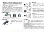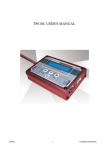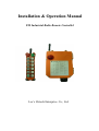
1
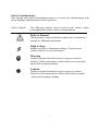
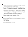
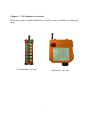
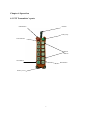
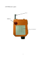
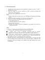
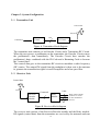
Installation & Operation Manual
F25 Industrial Radio Remote Controller
Lee’s Hi-tech Enterprise. Co., Ltd.
Table Of Contents
Safety Considerations ------------------------------------------------------------2
Part. 1
Operator’s Manual
Chapter 1
Warranty -----------------------------------------------------3
Chapter 2
Precautions Of Operation --------------------------------- 4
Chapter 3
Standard Accessories ---------------------------------------6
Chapter 4
Operation -----------------------------------------------------7
Chapter 5
Inspection and Fault Detection ---------------------------10
Part. 2
Technician’s Manual
Chapter 1
General Characteristics -------------------------------------11
Chapter 2
System Configuration ---------------------------------------12
Chapter 3
Installation and Function Setting --------------------------14
Chapter 4
Software -------------------------------------------------------19
1
Safety Considerations
This product and related documentation must be reviewed for familiarization with
safety markings and instructions before operation.
Safety Symbols
The following symbols may be found on the remote control
or throughout the remote control’s documentation.
Refer to Manual
When product is marked with this symbol refer to instruction
manual for additional information.
High Voltage
Indicates presence of hazardous voltage. Unsafe practice
could result in severe personal injury.
Warning
Denotes a hazard. Included text gives proper procedures.
Failure to follow instructions could result in severe personal
injury and/or property damage.
Caution
Denotes a hazard. Included text gives proper procedures.
Failure to follow instructions could result in minor personal
injury and/or properly damage.
2
Part 1. Operator’s Manual
Chapter 1 Warranty
1-1 Warranty
Lee’s Hi-Tech Enterprises Co., Ltd. guarantees that this product meets its
published specifications at the time of shipment from the factory. Under proper
installation it should work as expected.
1-2 Warranty Period
This equipment is warranted against defects in material and manufacturing for a
period of one year from the date of shipment. During the warranty period,
TELECRANE is responsible for necessary repairs as long as the product can be
proved to be defective.
For warranty service or repair this product must be returned to a service facility
designated by TELECRANE. Buyer will pay shipping charges to TELECRANE
while TELECRANE will pay return shipping charges.
1-3 Excluded Items
This warranty does not include consumptive parts such as batteries, fuses, buttons,
and relays. Also this warranty does not cover defects caused by improper
installation, improper or insufficient maintenance, unauthorized modification,
improper operation, ignorance of environmental specifications, or improper
software or interfacing.
1-4 Remarks
◎ No other warranty is expressed or implied, except for the above mentioned.
◎ The remedies provided herein are the buyer’s sole and exclusive remedies.
TELECRANE shall not be liable for any direct, indirect, special, incidental or
consequential damages.
3
Chapter 2 Precautions of Operation
2-1 Attention
◎Please carefully read the manual before installing and operating this device.
◎Due to the complex nature of this equipment it is necessary to read the entire
manual before installation.
◎Never dismantle the equipment by any unauthorized personnel, or equipment may
be damaged.
◎This manual is for reference only. Pleases consult your distributor for further
assistance.
◎The equipment has been strictly tested for quality before delivery from our plant.
However, this equipment must not be used in dangerous situations or where
damage may result.
◎After operation, shut off main power to the crane, power to receiver, and remove
transmitter key.
◎Transmitter should be placed in a safe area when not in use to avoid accidental
pressing of buttons.
◎The crane should be equipped with main power relay, limit switch and other safety
devices.
◎Don’t use equipment during lightening or high electrical interference conditions.
◎Make sure that the batteries are in good condition and power for receiver is correct.
◎Maintenance should only be done while the crane’s main power is off to prevent
electrical shock.
◎The contents of this manual may be amended by the manufacturer without notice.
◎The manufacturer may introduce new functions to the equipment as necessary,
therefore, the descriptions may change.
4
2-2 Precautions
☆ Operating in an industrial facility is relatively dangerous; therefore, operator must
have taken the adequate trainings in using F25 system.
☆ Those who operate the machine should be healthy and have good judgment in
regard to safety.
☆ Although the F25 transmitter is so durable and resistant for the fluctuating
temperature, care still need be taken to prevent it from the severe impact or
pressure.
☆ During operation, if the power supply of the transmitter’s batteries is insufficient,
the transmitter will send out EMS signal first to de-energize all of motion relays
inside the receiver to stop crane’s moving, and then the LED indicator on
transmitter will flash in red constantly. At this moment, the batteries need to be
replaced and all of four batteries should be replaced at the same time.
☆ If the severe interference occurred the equipment should be stopped at once.
☆ Please take the batteries out when the equipment will not be used for a long time.
☆ Be sure to know the “Procedures of Emergency “ as follows.
2-3 Procedures of emergency
In case of an Emergency, please follow the steps below and ask the distributor for
service immediately.
1.
2.
3.
4.
Press "EMS" button.
Turn the key to "OFF" position and remove it.
Switch off the main power of crane.
Advise the distributor to find out the reason.
5
Chapter 3
F25 Standard Accessories
When you acquire a standard and full set of F25 system, it includes the following
items.
(1)Transmitter, one unit.
(2)Receiver, one unit.
6
Chapter 4 Operation
4-1 F25 Transmitter’s parts
EMS Button
Antenna
Rotary Key
LED Indicator
Motion
Buttons
Start Button
Horn Button
Battery Cover
7
4-2 F25 Receiver’s parts
Antenna
Power- On
Indicator
Wiring Diagram
8
4–3 General Operation
1. Install four AA size batteries in the transmitter and make sure the "+" and "-"
direction are correct.
2. Insert the rotary key into the keyhole at "OFF" position and then turn
clockwise to "ON" position.
3. Press the "Start" pushbutton to Power-On.
Note:
If fail to follow the procedure above, the LED light will indicate fast flashing
in red.
4. Operate normally according to the function setting has done.
5. Please proceed the following procedure after operation.
a) Press EMS mushroom
b) Turn the rotary key to "OFF" position.
c) Remove the rotary key.
d) Remove the batteries when the equipment is not going to be used for a
long period of time
Note:
1. There is a 3-stage power indicating function with LED display.
(1) "Green color": Sufficient power to operate transmitter.
(2) "Yellow color": Power is depleting. Operation must be stopped
immediately (for example: down the loads to ground) to replace batteries.
(3) "Red color": Insufficient power. Transmitter will send out an emergency
stop signal to the receiver due to insufficient power. Operator should avoid
this situation in order to maintain the safety of operation.
2. Turn the rotary key of the transmitter to "OFF" position; it will not only shut
off the motion of the receiver but also save the power. Otherwise, the
transmitter will keep staying in the standby mode and causing more power
consumption.
9
Chapter 5. Inspection and Fault Detection
5–1 Inspection
Daily inspection is important and will ensure the safety of operation. Inspection
should include "emergency stop" and other safety devices and functions. If there is
any doubt, operation must be stopped immediately and problems must be solved
before resume of operation.
5–2 Fault Detection
F25 is equipped with simple fault detection mechanism. While start and during the
operation, fault detection mechanism will indicate the faulty signals if any
malfunction is detected. Operator must understand the faulty signals and notify the
maintenance personnel.
5-2-1 Transmitter Fault Detection
If the LED light on the transmitter is fast flashing in red, then there must be the
causes as follows:
1. Some of the push buttons are jammed or stock.
2. EMS button has not been released.
3. Fail to follow the correct Power-On procedure.
5-2-2 Receiver Fault Detection
Malfunction Types and LED indicators of the receiver are listed as follows:
G1
R1
G2
On
Blink
Simultaneously
with R1
Blink
Alternately
with R1
R2
On
Blink
Simultaneously
with G1
Blink
Alternately
with G1
Malfunction Type
MCU1 or MCU2 Fault
Main (EMS) Relays Fault
Relay Driver Buffer Fault
Some of the Motion Relays
are Jammed
Blink
On
10
Receiver fails to receive the
correct signal and the Passive
EMS action activated.
Part 2. Technician’s Manual
Chapter 1 General Characteristic
1–1 General Specifications
- Operation Frequency--------------------- : 433.05~434.79MHz
- Hamming Distance ----------------------- : ≧ 4
- I.D. Code----------------------------------- : 220 sets (set by factory, never repeated)
- Temperature Range----------------------- : -40℃ ~ +85℃
- Channel Spacing-------------------------- : 25 KHz
- Maximum Operation Range------------ : Up to 100 Meters
- Structure----------------------------------- : Reinforced Plastic and Glass Fiber
- Protection Degree------------------------ : IP 65
1–2 Transmitter Specifications
- Power Supply----------------------------- RF Power---------------------------------- Pushbutton Type-------------------------- Dimensions-------------------------------- Weight-------------------------------------
: Four 1.5 volts Batteries (AA Size)
: < 10 mW
: Two step mechanical switch
: 186x61x51mm (LxWxH)
: about 265g (including batteries)
1–3 Receiver Specifications
- Power Supply----------------------------- : 48/110/ 220/380VAC (50/60Hz), ±20%
- Sensitivity----------------------------------: −110dBm
- Output Relays----------------------------- : 5A/250VAC
- Dimensions-------------------------------- : 200x162x107mm (LxWxH)
- Weight------------------------------------- : about 1220g(excluding wire cable)
11
Chapter 2. System Configuration
2–1 Transmitter Unit
Control Data
Antenna
Encoder
Circuit
Pushbuttons
Data
Transmitter
RF Circuit
Figure A. Transmitter block diagram
The transmitter unit consists of an Encoder Circuit and a Transmitter RF Circuit.
When the user presses a pushbutton on the transmitter, the Encoder Circuit senses
the pushbutton’s data immediately. The Encoder Circuit then encodes the
pushbutton’s data, combined with the ID Code and a Hamming Code to become
the "control data".
This control data goes to the transmitter RF circuit to modulate a radio frequency
(RF) carrier. The output FM signal from the modulator is then sent to the antenna
to generate the transmission signal via an RF amplifier and a low-pass filter.
2–2
Receiver Unit
Control data
ANT
Cable
Command
Receiver/
Decoder
Module
Relay
Module
Relay contact outputs
(Connects to cranes
or other mechanical
devices)
Figure B. Receiver block diagram
The receiver unit consists of the Receiver/Decoder module and the Relay module.
RF signals (control data) from the transmitter are received by the antennas and sent
12
to the Receiver/ Decoder module. The main functions of the Receiver/Decoder
module are to process the RF signal from the transmitter through the signal
processing circuits, consisting of the band-pass filter, RF amplifier, mixer, IF
amplifier, demodulator, error detection, error correction circuits, and decoder in
order to generate a control command sent to the Relay module to drive the
corresponding relay.
The Relay element is the interface of the Remote Controller to a crane or other
mechanical device. The wiring between the relay contact outputs and the control
circuit (or control box) of the crane or mechanical device can be arranged by the
user.
2-3 Error detection/Error correction by software
F25 system employs the theory of "Error-Control Coding" used on Computer
system, and incorporates the "Control Data Code" and the principle of "Error
detection/Error correction" of Hamming Distance to edit and complete the "Code
Word" was so-called "Hamming Code" which may ensure the control data with
accuracy in process of transmission, and also equip with function of automatic
"Error detection/Error correction" to make sure the safety in operation of F25
system remote control.
2-3-1 Data Stream
As shown as below, before the receiver’s relays output to control the equipment’s
movement, the data including SYNC, ID-CODE, COMMAND and SUM must be
checked twice to further make sure, so the data transmission becomes more safe
and reliable.
ID-CODE
SYNC
COMMAND
SUM
SYNC
character 16 bits
Action commands 72
Bits with HAMMING
ENCODED
Security ID-CODE
Check SUM
48 bits with HAMMING
8 bits with
ENCODED
HAMMING
ENCODED
TOTAL DATA LENGTH= 144 bits
13
SYNC
2-3-2 Hamming Code
It is shown as below, the Code Word length is equal to 8, the Data Bit is equal to 4,
the Hamming Distance is equal to 4, it means that HAMMING CODE (8,4,4) can
correct single-bit errors and also detect double-bit errors.
A
8
BINARY
HAMMING CODE (8,4,4)
1010
1000
10100101
10010110
Chapter 3. Installation And Function Setting
3–1
Precautions during installation
1. Observe all safety precautions when climbing the crane.
2. Turn off the main power source of cranes before installation to avoid electric
shock.
3. Receiver must be installed in the way that it will not touch any part of the
building during the operation.
4. Receiver must be fastened safely.
5. Before installation, inspect the crane’s safety devices, and make sure
everything is in proper working condition.
6. Make sure you understand the crane circuits and power distribution as well as
the function setting of remote controller, to avoid incorrect wiring.
3–2
Transmitter Installation Instructions
Installation of batteries in the transmitter:
Insert batteries in proper direction into battery compartment. Attach and screw the
battery cap on the bottom of the transmitter.
3–3
Receiver Installation Instructions
3-3-1 Preparation for Installation
1. Provide all necessary tools.
2. Select a proper location.
a. Select a stable place.
b. Select a place where you can see the Receiver or Antenna.
14
c. Select a place where there is no spark, e.g. keep away from motors, relays,
magnetic switch and power cables.
d. Keep away from high-voltage wiring and device.
e. The Receiver’s box must be at least 3 cm away from the other obstacles.
3. Installation of proper power source
The input power source for receiver can be 48 VAC 50/60 Hz, 110VAC,
50/60 Hz or 220VAC, 50/60 Hz., or 380VAC, 50/60 Hz. After power source
is confirmed, one must connect the connector of initial coil of transformer to
the relay module properly.
3-3-2 Installation Sequence
1. Turn off the main power for crane.
2. Drill the holes for screws, install receiver and then fix the receiver with 6mm
screw nut on vibration- Resistant.
3. Connect the cable-assembly (provided) to the receiver and tighten the cables.
4. Connect cables to the control circuit of crane according to the receiver’s
wiring table and control contacts diagram.
Note:
Inspect and make sure that all wires are connected correctly.
5. Secure the cables between the receiver and crane so that cable cover (wrapper)
will not wear out due to the vibration of the crane
3-3-3 Control Contacts Diagram
15
3-4 Power Supply and Change power supply voltage
F25 receiver provides with 4 kinds of Transformer (24V/42V/230V 、
48V/110V/220V、110V/220V/380V、48V/220V/380V) that allows user to choose
based on the power input on site and the designated voltage will be set when the
receiver is made in factory.
Changing power supply voltage
3-4-1 Disconnect the power of receiver.
3-4-2 Remove the connector plug of the transformer from its original position.
3-4-3 Insert the connector plug into the new position.
3-4-4 Complete the procedure.
Note:
Users are allowed to select the different power source according to the respective
requirement. However, the transformer must be changed. Please check with your
local distributor for replacement of the transformer if necessary.
3-5 Remote Channel Changing and Remote Pairing
Note: Before operating, one must make sure that the communication status between
transmitter and receiver is at good condition.
3-5-1 Remote Channel Changing
Remote Channel Changing allows the transmitter to notify the receiver to perform the
channel changing by radio remotely. After receiving the command from the
transmitter, the receiver will automatically search and select a clear and suitable
channel of frequency. In the mean time, the channel of frequency selected by the
receiver will be sent back to transmitter and replace the original channel with this
new one. The followings are the procedure of Remote Channel Changing:
16
1. Depress EMS mushroom pushbutton and turn the rotary key to “OFF” position.
2. Depress “START” pushbutton and hold it down, then turn the rotary key from
“OFF” to “ON” position simultaneously. At this time, LED will fast flash in red,
yellow, and green color alternately. This indicates that the transmitter is in the
remote setting mode.
3. Press the “UP” pushbutton. At this time, LED will change to flash in yellow
quickly. This indicates that it is performing the Channel Changing function.
4. When LED changes to flash 4 times in green and goes off, then the Channel
Changing is completed. If LED changes to flash 4 times in red, then the Channel
Changing is failed. You must go back to step 1 and redo the procedure again.
5. After completing the Channel Changing, turn the rotary key from “ON” to “OFF”
position and follow the correct power on procedure. Then, the controller is ready to
be normally used again.
3-5-2 Remote Pairing
Remote Pairing allows the transmitter to actively search the receiver to be paired on
site. After confirming the receiver, the data saved in the receiver, including the
functions settings, ID Code, and the Channel setting, will be download to the
transmitter by radio. In this way, the trouble and the risk of climbing to the receiver
can be eliminated. The procedures are as follows.
1. Depress EMS mushroom pushbutton and turn the rotary key to “OFF” position.
2. Depress “START” pushbutton and hold it down, then turn the rotary key from
“OFF” to “ON” position simultaneously. At this time, LED will quickly flash in
red, yellow, and green color alternately. This indicates that the transmitter is in the
remote setting mode.
3. Press the “DOWN” pushbutton. At this time, LED will change to fast flash in
green and red color alternately. This indicates that it is performing the Remote
Pairing function and searching the receivers available on site.
4. When LED changes to flash in green, it means that it has found a receiver ready to
be paired.
5. At this time, you may press the “START” pushbutton to confirm that the receiver
is the one to be paired. The power-on indicator of the receiver that has been
searched will be turned on and the horn will also make a sound at the same time.
6. If the receiver is not the one to be paired, then press “DOWN” pushbutton to skip
it and go back to step 4 to continue the searching process for the next receiver.
7. If the receiver is the one to be paired, then press “UP” pushbutton to continue the
procedure. At this time, LED will change to flash in yellow. It means that the
transmitter is downloading the data from the paired receiver.
8. When LED turns to green, then press “UP” pushbutton to conclude the procedure
above. At this time, LED will change to flash in green 4 times and go off. It means
that the Remote Pairing is completed.
17
9. After completing the Remote Pairing, turn the rotary key from “ON” to “OFF”
position and follow the correct power on procedure. Then, the controller is ready
to be normally used again.
P.S. If the transmitter did not find any receiver, LED will flash in red 4 times and go
off. It means that the Remote Pairing is failed and need to restart the procedures again.
3-6 Function Setting
The radio data can be read and written by using Copier or F25 software through PC.
Transmitter
Receiver
Copier
*Please refer to the copier user manual for more detail.
This remote control system can be set according to the working condition and
operator’s need for the following promotes: pushbutton function, EMS neglected
function, search function, interference neglected time…etc. This enables the remote
controller to perform the most effective operation and to provide the safest operation.
Please refer to the Software Function Setting in Chapter 4, next chapter.
18
Chapter 4 Software
4-1 Software Installation
F25 Software Installation
1. Insert F25 CD-ROM, the installation
program will be executed automatically.
2. Press the “icon” and continue the installation
3. Press “Continue” button
4. Press “OK” button and installation of
F25 software program is completed.
19
How to start F25 Program
1. Press “Start” button
2. Select“Programs”
3. Select“F25 SETUP PROGRAM”
4. Then select“F25 SETUP
PROGRAM”
How to use F25 Program
Note: Make sure both power of transmitter and receiver is remaining OFF when
reading or writing the data.
Reading Data
1. Connect program Interface Cable (USB) into
transmitter or receiver.
2. Press “Read R/C”.
3. Press “OK” when finish.
Writing Data
1. Connect program Interface Cable (USB) into
transmitter or receiver.
2. Press “Write R/C”.
3. Press “OK” when finish.
Pushbutton function setting
1. Read data from Transmitter (Receiver).
2. From main (Function-Setting) page, press any button group you would like to
program. The pushbutton function table will be pop up immediately. Select any
function block from the table (as shown on the figure). Return to main page
automatically when finish the selection.
3. Repeat the above procedure 1~3 if you wish to make any other function changes
on the pushbutton.
Remark: (1) For further information about the function definition, please refer to the
annex 1 for more detail.
(2) Press “EXIT” to close function table without change
20
(Function
User-Information
Customer data sheet: Allow you to store the
customer information such as company name,
purchasing date, address, and phone etc.
1. Click “User-Information”
2. Fill the information.
Saving data
To save radio function and customer data
1. Press Save button
2. Select the saving folder and file name then
press SAVE
Open File
To open file (data)
1. Press open file button
or select LOAD
2. Select the file name then press OPEN
21
Table)
Print
To print the screen
Press Printing
button
Note﹕
﹕Only in-use page will be printed when pressing printing button. In order to
print other page, please switch to another page and press the print button
again.
Exit F25 Program
Press exit button
22
4-2 Definition of Function Setting Terms
Normal
Toggle
ON/OFF
The relative relay is “ON” when the pushbutton is pressed and
held; and relay is “off” when the pushbutton is released.
Maintained function: the relay is operated by pressing and
releasing. Press the pushbutton and release once for “on”; press
and release again to turn off the relay.
Both pushbuttons are used to operate the same relay. Press the
ON pushbutton to activate the relay and press the OFF pushbutton
to de-activate the relay.
Interlock
The two pushbuttons are interlocked; it’s not possible to operate
two opposite functions at same time.
Non-Interlock
The two pushbuttons can be operated at the same time: When the
application allows operating at the same time two functions which
are usually opposite to one another.
Interlock Delay
Time
“Interlock Delay Time” is delay time between 2 opposite
pushbuttons are being press one after another. i.e.: while crane is
moving one direction (forward), moving opposite direction
(backward) immediately would be dangerous specially when
crane is hooking up the heavy object. The object may sway if
crane does not completely stop before moving into opposite
direction. Therefore the interlocked delay time could potentially
prevent it. Normally, the interlocked delay time should be larger
than the duration of crane stop.
“Bypass EMS” means that the relay relating to pushbutton will
not be controlled by EMS mushroom or emergency stop signal.
Bypass EMS
Control By EMS
Acc. Delay
“Control by EMS” means that the relay relating to pushbutton is
controlled by EMS mushroom or emergency stop signal.
This function uses to set the time interval between acceleration
relay (i.e. conduction-delayed time of acceleration relay). It is
suitable for accelerative operation only in order to prevent the
cranes directly runs to highest speed to damage the motor.
23
Dual Motor
When 1st step pushbutton is pressed, the 1st step relay turns ON, if
2nd step is being pressed then 2nd step relay turns ON and 1st step
relay turns OFF. (For dual motor hoist)
Relay
1st Step
2nd Step
Relay
Relay
Pushbutton
1st Step
ON
OFF
2nd Step
Dual Motor (1)
OFF
ON
The main function characteristic of Dual Motor (1) is same as
Dual Motor except the 1st step relay will not be activated
(bypass) while pushbutton is returning from 2nd step to 1st step.
Combination
When 2 buttons are being pressed simultaneously, it would result
for an additional relay output (as toggle) to suit some of the
special application such as lighting system.(No any extra
pushbutton required to save the space and cost)
*Combination setting is prohibited for magnetic devices.
Magnetic ON/OFF Both pushbuttons are used to operate the same relay. Press the
“Magnetic ON” pushbutton to activate the relay. If the operator
wants to de-activate the relay, he must keep pressing the
“Magnetic ON” pushbutton and then press the “Magnetic OFF”
pushbutton in the mean time. The purpose is to prevent the
operator from accidentally pressing the “Magnetic OFF”
pushbutton and dropping the load held by the magnetic sucking
disc.
R1,2,3 Toggle, R4 R1, R2, R3 pushbuttons are set as Toggle and R4 pushbutton set
Normal
as Normal. This function is applied when the crane has 2 trolleys
and need to control the trolleys separately or simultaneously.
Press R1 pushbutton to control Trolley A, Press R2 pushbutton to
control Trolley B, and Press R3 pushbutton to control both
Trolley A & B. Furthermore, R4 can independently perform the
Normal function and with 2 speed.
R1,2,3 Toggle, R4 R1, R2, R3 pushbuttons are set as Toggle and R4 pushbutton set
Toggle
as Toggle. This function is applied when the crane has 2 trolleys
and need to control the trolleys separately or simultaneously.
Press R1 pushbutton to control Trolley A, Press R2 pushbutton to
control Trolley B, and Press R3 pushbutton to control both
Trolley A & B. Furthermore, R4 can independently perform the
Toggle function.
24
R1,2,3 Toggle, R4 R1, R2, R3 pushbuttons are set as Toggle and R4 pushbutton no
No Use
use. This function is applied when the crane has 2 trolleys and
need to control the trolleys separately or simultaneously. Press R1
pushbutton to control Trolley A, Press R2 pushbutton to control
Trolley B, and Press R3 pushbutton to control both Trolley A & B
(Once R3 pushbutton is pressed, R4 replay is also activated with
R3 relay. At this time, R4 pushbutton is no longer available even
if it has been pressed.
R1,2,3 Toggle, R4 R1, R2, R3, and R4 pushbuttons are all set as Toggle. This
Group
function is applied when the crane has 4 trolleys and need to
control the trolley A, trolley B, trolley C, trolley D separately by
pressing each individual pushbutton respectively.
Power On Mode
Start-Pushbutton/Password:
Start-Pushbutton: It is the regular way to power on the receiver.
Password: The selection menu of key1, key2, key3, and key4 are
popped up when Password is chosen. Allow the operator to select
any combination of these 4 keys. Operator has to enter password
before turning on the transmitter. The purpose is to prevent the
unauthorized person from operating the remote controller or
machine.
Inching
The relative relay will be conducted within a certain time, in order
to operate with short and precision movement. There are 2 ways
to perform this function:
Dual Buttons Inching: Press and hold “START” pushbutton and
press the relative motion pushbutton to perform inching motion.
(When “Dual Buttons Inching” is chosen.)
Single Button Inching: Once “START” pushbutton is pressed,
just presses the relative motion pushbutton, then can perform
inching motion. To release this function, just press “START”
pushbutton again. (When “Single Buttons Inching” is chosen.)
Inching time
“Inching time” can be set from 0.01~2.0 seconds. This function is
used to operate crane with short and precise movement (e.g.
accurate position). “Inching Time” is the same as the working
time for the relative relay that is controlled by executing
“Inching” control function.
25
Transmit Mode
“Non-continuous transmitting mode”: After “Power-On”, the
transmitter will transmit the signal only when the pushbutton is
pressed. This mode can save the power of transmitter.
“Continuous transmitting mode”: Transmitter will continuously
transmit signal once transmitter is being Power-On.
Save Power
This function is used to turn off the Transmitter after a given idle
time. *Only available under “continuous transmitting” mode.
Auto-OFF(TX)
This function refers to turn off the Transmitter after a given idle
time while transmitting the signal to switch off the receiver main
relay. *Only available under “continuous transmitting” mode.
LED OFF-Time
This setting allows you to select the LED intermittent time to save
transmitter power. i.e.: If 1 second is selected, the LED will be
lighted every 1 second.
Passive Act
This function ensures safe operations, including when there are
disturbances that may affect the normal operating conditions. This
assures that when the machine operates, the control is not subject
to temporary and unexpected stops. Possible short interferences
are bypassed. The passive act can be select in 2 mode as below,
“Ry Off” If the interferences are larger than the pre-set time, the
receiver will turn off all the relays under “NORMAL” function
except the MAIN relay.
“Power-Off” If the interferences are larger than the pre-set time,
the receiver will turn off all the relays under “NORMAL”
function and “Control by EMS” including MAIN relay. The
receiver must be restart to operate again, follow the “Power-On”
procedure to restart the system.
Passive EMS
This setting allows the user to select the duration for the
interferences to be bypassed. If the interferences were within the
duration, then the receiver is still in operation, not affected. When
the interference is longer than the duration, then the receiver will
stop working. Usually, this action is called “Passive EMS”.
AUTO OFF (RX)
This function refers to turn off receiver after a given idle time.
Receiver MAIN relay will be turned off automatically. Normally
this function is cooperated with “non-continuous “transmitting”
mode to prevent any unintentional radio.
26
Start-Alarm
This function allows the user to activate the alarm of the receiver
to work or not to work. If the “Enable (2 sec)” is chosen, then the
alarm will make a 2-second sound when the receiver is powered
on/off.
TxPower(Range)
The emission power of the transmitter is adjustable according to
the user’s requirement. This options is shown as transmission
distance ranging from 20m to 500m, 8 steps to choose.
The transmission distance is strictly subject to the local
environmental factors. Therefore, it might be different from place
to place and it is for reference only.
Jam Detect
This function is to allow the user to activate the “relay jam detect
circuit” of the motion relays, UP/DOWN, EAST/WEST,
SOUTH/NORTH, or not.
If the option “Enable” is chosen, then the circuit is activated and
it will control the EMS relay to stop working when the jammed
relay is detected.
Remote Channel
Changing
When the option “Enable” is chosen, then the “Remote Channel
Changing” is allowed to perform. See Section 3-5-1 for the
procedure of remote setting. When the option “Disable” is chosen,
then the “Remote Channel Changing” cannot be performed.
Remote Pairing
When the option “Enable” is chosen, then the “Remote Pairing” is
allowed to perform. See Section 3-5-2 for the procedure of remote
setting. When the option “Disable” is chosen, then the “Remote
Pairing” cannot be performed.
Channel
This setting allows the user to choose the Operating Frequency
for the remote controller. There are 70 channels in total can be
selected, CH1~CH70.
27