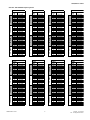
1
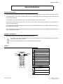
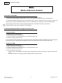
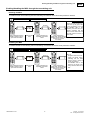
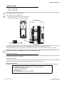
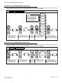
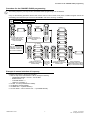
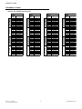
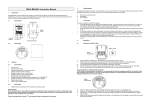
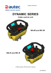
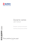
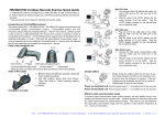
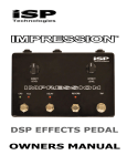
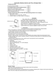
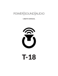
Working frequency (radio modules AIRTR08LM and AIRRT32NM)
IMPORTANT INFORMATION
Information provided in this manual is used for the installation of the radio remote control on the machine and for its maintenance.
Information provided in this manual allows to disable, enable and set some radio remote
control's functions that may have impacts on the risk assessment related to the machine; this assessment must be carried out to decide whether the machine can be radio
remote controlled.
Information provided in this manual cannot be used and performed by people who are
not competent, responsible for and authorized to do that.
The person in charge for the machinery's safety must keep information contained in this
manual reserved.
Those who use this information must also have been trained about the radio remote
control and its risks by Autec's personnell or by people authorized by Autec.
Autec cannot be held liable for responsibilities resulting from the modification of these
functionalities after the product sale.
AIR SERIES
STOP
1
2
3
S1
R
G
4
S2
S3
Working frequency (radio modules AIRTR08LM and AIRRT32NM)
FUNCT. START
General instructions
General Section
General instructions
This manual aims at providing information to enable, disable and modify the features of Autec Air series' radio remote controls.
This manual and the “user manual” need to be fully read and understood by those who decide upon and/or modify the radio
remote control's features.
Contact Autec if any of the instructions and/or warnings provided in this manual are not clear.
No part of this manual may be reproduced, in any form or by any means, without written permission of Autec (including recording and photocopying).
All operations described in this manual must be carried out by qualified technicians who are suitably trained with respect to
the relevant norms and laws.
As for instructions and warnings regarding the machine where the radio remote control is to be installed, follow the instructions
given in the machine's manual.
Symbol conventions
This manual contains two symbols that highlight special indications.
This symbol marks all extremely important indications and information: if they are not respected, this may result in
critical danger for people or property.
This symbol identifies all texts in the manual that shall be read carefully.
Caption
Signals
LED is off
LED blinks once in a second
STOP
LED 1
LED 2
LED 3
1
2
3
S1
R
G
4
S2
LED blinks twice in a second
Red LED
green LED
LED 4
LED blinks three times in a second
LED is steady on
S3
FUNCT. START
1
LED repeats 1 blink and an off phase
2
LED repeats 2 blinks and an off phase
3
LED repeats 3 blinks and an off phase
4
LED repeats 4 blinks and an off phase
5
LED repeats 5 blinks and an off phase
Pushbuttons
pushbutton is released
pushbutton pressed to first step
pushbutton is pressed
LIIA0100E0-02.fm
1
AUTEC - Air Series
A8 - Configuration Menu
MSC
Description of the MSC
MSC
Mode of Service Control
Description of the MSC
The MSC radio remote control's working mode is used to enter the installation menus.
It is possible to enable/disable the MSC either by acting on the receiving unit or by acting on the transmitting unit.
The SERVICE CONTROL programming can only enable the MSC mode if it is enabled as a factory setting. Therefore, the
MSC mode can only be enabled after making sure that it is activated (ON) by checking this in the technical data sheet.
When the radio remote control is in MSC, pressed pushbuttons do not activate the receiving unit's outputs.
Disable the MSC mode to start controlling the machine again.
Enabling/disabling the MSC through the receiving unit
Enabling the MSC
To enable the MSC, do the following.
1. Remove power from the receiving unit.
2. Open the receiving unit and set DIP switch 2 on the mother board to ON.
3. Close the receiving unit and power it.
At the next radio remote control's start up, the green LED in the transmitting unit and the ENABLE LED in the receiving unit
blink twice per second, indicating that the radio link has been built and the radio remote control is in MSC mode.
Disabling the MSC
To disable the MSC do the following.
1. Remove power from the receiving unit.
2. Open the receiving unit and set DIP switch 2 on the mother board to OFF.
3. Close the receiving unit and power it.
At next radio remote control start-up:
- the green LED in the transmitting unit blinks slowly, indicating that the radio remote control is ready to control the machine
- the ENABLE LED in the receiving unit blinks, indicating that the radio link is built.
AUTEC - Air Series
A8 - Configuration Menu
2
LIIMSC0AE0-03.fm
Enabling/disabling the MSC through the transmitting unit
MSC
Enabling/disabling the MSC through the transmitting unit
Enabling the MSC
To enable the MSC do the following with the transmitting unit switched off and the STOP pushbutton released.
Transmitting unit off
STOP pushbutton released
STOP
STOP
1
2
3
S1
S1
1
2
3
R
G
4
STOP
R
G
4
S2
1
2
3
R
G
4
S2
S1
1
2
3
PIN
FUNCT. START
ENABLE
R
G
4
FUNCT. START
Keep pushbuttons S2 and
START pressed until the
green LED illuminates
Enter the PIN
code
R
G
4
S2
1
2
3
1
2
3
R
G
4
FUNCT. START
Press pushbutton S1
repeatedly until LED 2
blinks
Keep pushbuttons
FUNCTION, START and S2
pressed until the green LED
is steady on to save
this setting
NOTE
At the next radio remote control's start up, the green LED
in the transmitting unit and
the ENABLE LED in the
receiving unit blink twice per
second, indicating that the
radio link has been built and
the radio remote control is in
MSC mode.
Disabling the MSC
To disable the MSC do the following with the transmitting unit switched off and the STOP pushbutton released.
Transmitting unit off
STOP pushbutton released
STOP
1
2
3
S1
STOP
R
G
4
S2
1
2
3
S1
1
2
3
R
G
4
Keep pushbuttons S2 and
START pressed until the
green LED illuminates
LIIMSC0AE0-03.fm
1
2
3
DISABLE
R
G
4
1
2
3
PIN
FUNCT. START
FUNCT. START
Enter the PIN
code
NOTE
At next radio remote control
S1
start-up:
- the green LED in the transR
1
mitting unit blinks slowly,
G
2
3
4
indicating that the radio
remote control is ready to
FUNCT. START
control the machine
- the ENABLE LED in the
receiving unit blinks, indiKeep pushbuttons
cating that the radio link is
FUNCTION, START and S2
pressed until the green LED
built.
is steady on to save
this setting
STOP
R
G
4
S2
Press pushbutton S1
repeatedly until LED 1
blinks
3
R
G
4
S2
AUTEC - Air Series
A8 - Configuration Menu
WORKING FREQUENCY
WORKING FREQUENCY
WORKING FREQUENCY
Programming procedures provided hereafter allow to set the radio remote control's radio link features; these must
comply with the laws and standards enforced in the market where they are used. In order for the system “machine+radio remote control” to be compliant and therefore to be used, it shall comply with such laws and standards: if it does
not, the system may be stopped and impounded by competent supervisory bodies.
Autec cannot be held responsible if the radio remote control is set with forbidden frequencies.
Programming related to “Working frequency” is as follows:
- BANK GROUP.
The BANK GROUP programming is used to set the frequency bank used by the radio remote control.
- RADIO MODE.
The RADIO MODE programming is used to choose the automatic scan mode or the manual selection of frequency.
- CHANNEL BANK.
The CHANNEL BANK programming is used to choose the working frequency.
It is only possible to enter the BANK GROUP, RADIO MODE and CHANNEL BANK programming if the radio remote control
is in MSC working mode (Mode of Service Control).
When the setting procedure has ended, disable the MSC mode to start controlling the machine again.
Write down all changes in the technical data sheet.
Enter the programming related to the BANK GROUP, RADIO MODE and CHANNEL BANK programming without modifying
the setting to check options set through those procedures.
Leaving programming without modifying settings
You can leave any programming in any moment without modifying the settings; do as follows:
1. press the STOP pushbutton
2. wait approx. 10 seconds without pressing any pushbutton.
AUTEC - Air Series
A8 - Configuration Menu
4
LIIWFR1AE0-03.fm
WORKING FREQUENCY
FREQUENCY BAND
AIR series radio remote controls can work at two different frequency bands:
- 433.050 - 434.790 MHz
- 915.000 - 928.000 MHz.
The frequency band is selected by DIP 1 under the transmitting unit's battery and DIP 1 on the receiving unit's mother board.
These DIPs shall be set in the same way.
DIP 1 shall be set when the unit is off:
- press the STOP pushbutton in the transmitting unit
- disconnect power supply from the receiving unit.
Receiving unit
12
ON
1 2
ON
Transmitting unit
DIP
ON
1 2
ON: 915-928MHz
OFF: 433.05-434.79MHz
If a radio remote control shall be used in the United States, after setting DIP 1 in the ON position, this DIP switch must be
blocked (e.g. with glue, enamel...) so that it is not possible for operators to modify the frequency band.
This request arises from FCC requirements, and it is therefore necessary for the radio remote control to be compliant.
Before putting a radio remote control into the United States' market, it is compulsory to check that DIP 1 on the transmitting unit is blocked as described above: if it is not, it must be blocked.
Frequency use mode
The RADIO MODE programming allows to set the radio remote control in automatic frequency scan mode (AUTO) or in manual frequency selection mode (MANUAL).
Automatic scan mode
In AUTO mode, the radio remote control automatically chooses the working frequency among the frequencies in the selected
BANK GROUP. The radio remote control checks that a frequency is free before using it.
Manual selection mode
In MANUAL mode, the radio remote control uses a fixed working frequency, that can be set with the following procedure:
1. With the help of the frequency table, identify FREQUENCY BAND, LOGICAL CHANNEL,
CHANNEL BANK and BANK GROUP related to the desired frequency.
2. Set FREQUENCY BAND with DIP 1.
3. Set RADIO MODE to MANUAL.
4. Set BANK GROUP.
5. Set CHANNEL BANK and LOGICAL CHANNEL.
LIIWFR1AE0-03.fm
5
AUTEC - Air Series
A8 - Configuration Menu
Procedure for the BANK GROUP programming
Procedure for the BANK GROUP programming
Carry out the following procedure with the radio remote control on and in MSC mode (in this condition the green LED in the
transmitting unit blinks twice per second and the ENABLE LED in the receiving unit blinks).
MSC enabled
Radio remote control on
BANK GR. 0
NOTE
See the FREQUENCY TABLE
to choose the BANK GROUP:
- 433.050 - 434.790 MHz:
four BANK GROUPs (0-3)
- 915.000 - 928.000 MHz:
eight BANK GROUPs (0-7).
R
G
4
1
2
3
BANK GR. 1
R
G
4
1
2
3
BANK GR. 2
1
2
3
R
G
4
BANK GR. 3
1
2
3
R
G
4
BANK GR. 4
STOP
STOP
1
2
3
1
2
3
R
G
4
S2
S1
R
G
4
S2
S1
1
2
3
STOP
BANK
GROUP
1
2
3
R
G
4
1
2
3
R
G
4
S2
S1
1
2
3
R
G
4
S2
S1
R
G
4
FUNCT. START
FUNCT. START
STOP
1
2
3
R
G
4
BANK GR. 5
1
2
3
R
G
4
STOP
1
2
3
R
G
4
S2
S1
1
2
3
BANK GR. 6
FUNCT. START
FUNCT. START
R
G
4
1
2
3
R
G
4
FUNCT. START
BANK GR. 7
1
2
3
Keep pushbuttons START,
FUNCTION and S1
pressed until the green
LED illuminates
Press pushbutton S1
repeatedly until LED 2
and LED 3 illuminate
Press pushbutton S2 to
confirm setting
R
G
4
Press pushbutton S1
repeatedly to choose the
desired option
Keep pushbuttons
FUNCTION, START and S2
pressed until the green LED is
steady on to save this setting
Procedure for the RADIO MODE programming
Carry out the following procedure with the radio remote control on and in MSC mode (in this condition the green LED in the
transmitting unit blinks twice per second and the ENABLE LED in the receiving unit blinks).
MSC enabled
Radio remote control on
STOP
STOP
1
2
3
S1
1
2
3
R
G
4
S2
S1
STOP
R
G
4
S2
1
2
3
S1
STOP
R
G
4
S2
1
2
3
S1
R
G
4
S2
RADIO MODE
1
2
3
FUNCT. START
Keep pushbuttons START,
FUNCTION and S1
pressed until the green
LED illuminates
AUTEC - Air Series
A8 - Configuration Menu
1
2
3
R
G
4
R
G
4
FUNCT. START
Press pushbutton S1
repeatedly until LED 1,
LED 2 and LED 3 illuminate
1
2
3
AUTO
STOP
R
G
4
1
2
3
S1
R
G
4
S2
1
2
3
MANUAL
FUNCT. START
Press pushbutton S2 to
confirm setting
6
FUNCT. START
1
2
3
R
G
4
Press pushbutton S1
repeatedly to choose the
desired option
R
G
4
FUNCT. START
Keep pushbuttons
FUNCTION, START and S2
pressed until the green LED is
steady on to save this setting
LIIWFR1AE0-03.fm
Procedure for the CHANNEL BANK programming
Procedure for the CHANNEL BANK programming
The working frequency can only be set if the RADIO MODE programming is set to MANUAL.
Carry out the following procedure with the radio remote control on and in MSC mode (in this condition the green LED in the
transmitting unit blinks twice per second and the ENABLE LED in the receiving unit blinks).
MSC enabled
Radio remote control on
STOP
STOP
1
2
3
S1
1
2
3
R
G
4
S2
S1
1
2
3
STOP
R
G
4
S2
CHANNEL
BANK
1
2
3
R
G
4
1
2
3
R
G
4
S2
S1
LOGIC CH. 0
R
G
4
1
2
3
R
G
4
LOGIC CH. 1
FUNCT. START
FUNCT. START
1
2
3
FUNCT. START
R
G
4
LOGIC CH. 2
Keep pushbuttons START,
FUNCTION and S1
pressed until the green
LED illuminates
Press pushbutton S1
repeatedly until LED 4 illuminates
STOP
1
2
3
S1
R
G
4
S2
1
2
3
R
G
4
CH. BANK 1
1
2
3
R
G
4
1
2
3
FUNCT. START
R
G
4
STOP
1
2
3
S1
STOP
R
G
4
S2
1
2
3
S1
R
G
4
S2
FUNCT. START
R
G
4
LOGIC CH. 5
1
2
3
R
G
4
STOP
1
2
3
S1
R
G
4
S2
1
2
3
FUNCT. START
1
2
3
R
G
4
R
G
4
FUNCT. START
LOGIC CH. 7
R
G
4
Press pushbutton S1
repeatedly to choose the
desired setting
1
2
3
LOGIC CH. 6
CH. BANK 3
1
2
3
R
G
4
LOGIC CH. 4
CH. BANK 2
1
2
3
R
G
4
LOGIC CH. 3
CH. BANK 0
NOTE
See the FREQUENCY
TABLE to choose the
CHANNEL BANK and
the LOGIC CHANNEL:
1
2
3
Press pushbutton S2 to
confirm setting
1
2
3
Press pushbutton S2 to
confirm setting
R
G
4
Press pushbutton S1
repeatedly to choose the
desired option
Keep pushbuttons
FUNCTION, START and S2
pressed until the green LED is
steady on to save this setting
Example of manual selection of frequency
Example of frequency to be set: 433.700 MHz.
1. With the help of the FREQUENCY TABLE, identify the following:
- FREQUENCY BAND = 433.050 - 434.790 MHz
- BANK GROUP = 2
- CHANNEL BANK = 3
- LOGICAL CHANNEL = 1
2. Set DIP 1 to OFF (FREQUENCY BAND).
3. Set MANUAL (RADIO MODE).
4. Set BANK GR. = 2 (BANK GROUP).
5. Set CH. BANK = 3 and LOGICAL CH. = 1 (CHANNEL BANK).
LIIWFR1AE0-03.fm
7
AUTEC - Air Series
A8 - Configuration Menu
FREQUENCY TABLE
FREQUENCY TABLE
AUTEC - Air Series
A8 - Configuration Menu
8
CH. BANK 0
CH. BANK 1
CH. BANK 2
BANK GR. 2
LOGIC
[MHz]
CH.
0
433.075
1
433.100
2
433.125
3
433.150
4
433.175
5
433.200
6
433.225
7
433.250
0
433.275
1
433.300
2
433.325
3
433.350
4
433.375
5
433.400
6
433.425
7
433.450
0
433.475
1
433.500
2
433.525
3
433.550
4
433.575
5
433.600
6
433.625
7
433.650
0
433.675
1
433.700
2
433.725
3
433.750
4
433.775
5
433.800
6
433.825
7
433.850
CH. BANK 3
CH. BANK 2
CH. BANK 1
CH. BANK 0
BANK GR. 1
LOGIC
[MHz]
CH.
0
433.100
1
433.150
2
433.200
3
433.250
4
433.300
5
433.350
6
433.400
7
433.450
0
433.500
1
433.550
2
433.600
3
433.650
4
433.700
5
433.750
6
433.800
7
433.850
0
433.900
1
433.950
2
434.000
3
434.050
4
434.100
5
434.150
6
434.200
7
434.250
0
434.300
1
434.350
2
434.400
3
434.450
4
434.500
5
434.550
6
434.600
7
434.650
CH. BANK 3
CH. BANK 0
CH. BANK 1
CH. BANK 2
BANK GR. 0
LOGIC
[MHz]
CH.
0
433.075
1
433.125
2
433.175
3
433.225
4
433.275
5
433.325
6
433.375
7
433.425
0
433.475
1
433.525
2
433.575
3
433.625
4
433.675
5
433.725
6
433.775
7
433.825
0
433.875
1
433.925
2
433.975
3
434.025
4
434.075
5
434.125
6
434.175
7
434.225
0
434.275
1
434.325
2
434.375
3
434.425
4
434.475
5
434.525
6
434.575
7
434.625
CH. BANK 3
CH. BANK 3
CH. BANK 2
CH. BANK 1
CH. BANK 0
433.050 - 434.790 MHz frequency band
BANK GR. 3
LOGIC
[MHz]
CH.
0
434.075
1
434.100
2
434.125
3
434.150
4
434.175
5
434.200
6
434.225
7
434.250
0
434.275
1
434.300
2
434.325
3
434.350
4
434.375
5
434.400
6
434.425
7
434.450
0
434.475
1
434.500
2
434.525
3
434.550
4
434.575
5
434.600
6
434.625
7
434.650
0
434.675
1
434.700
2
434.725
3
434.750
4
434.775
5
434.250
6
434.450
7
434.650
LIIWFR1AE0-03.fm
FREQUENCY TABLE
LIIWFR1AE0-03.fm
9
CH. BANK 0
CH. BANK 1
CH. BANK 2
CH. BANK 3
CH. BANK 0
CH. BANK 1
BANK GR. 6
LOGIC
[MHz]
CH.
0
915.350
1
915.750
2
916.150
3
916.550
4
916.950
5
917.350
6
917.750
7
918.150
0
918.550
1
918.950
2
919.350
3
919.750
4
920.150
5
920.550
6
920.950
7
921.350
0
921.750
1
922.150
2
922.550
3
922.950
4
923.350
5
923.750
6
924.150
7
924.550
0
924.950
1
925.350
2
925.750
3
926.150
4
926.550
5
926.950
6
927.350
7
927.750
CH. BANK 2
CH. BANK 2
CH. BANK 1
CH. BANK 0
BANK GR. 5
LOGIC
[MHz]
CH.
0
915.300
1
915.700
2
916.100
3
916.500
4
916.900
5
917.300
6
917.700
7
918.100
0
918.500
1
918.900
2
919.300
3
919.700
4
920.100
5
920.500
6
920.900
7
921.300
0
921.700
1
922.100
2
922.500
3
922.900
4
923.300
5
923.700
6
924.100
7
924.500
0
924.900
1
925.300
2
925.700
3
926.100
4
926.500
5
926.900
6
927.300
7
927.700
BANK GR. 2
LOGIC
[MHz]
CH.
0
915.150
1
915.550
2
915.950
3
916.350
4
916.750
5
917.150
6
917.550
7
917.950
0
918.350
1
918.750
2
919.150
3
919.550
4
919.950
5
920.350
6
920.750
7
921.150
0
921.550
1
921.950
2
922.350
3
922.750
4
923.150
5
923.550
6
923.950
7
924.350
0
924.750
1
925.150
2
925.550
3
925.950
4
926.350
5
926.750
6
927.150
7
927.550
CH. BANK 3
CH. BANK 3
CH. BANK 2
CH. BANK 1
CH. BANK 0
BANK GR. 1
LOGIC
[MHz]
CH.
0
915.100
1
915.500
2
915.900
3
916.300
4
916.700
5
917.100
6
917.500
7
917.900
0
918.300
1
918.700
2
919.100
3
919.500
4
919.900
5
920.300
6
920.700
7
921.100
0
921.500
1
921.900
2
922.300
3
922.700
4
923.100
5
923.500
6
923.900
7
924.300
0
924.700
1
925.100
2
925.500
3
925.900
4
926.300
5
926.700
6
927.100
7
927.500
CH. BANK 3
CH. BANK 0
CH. BANK 1
CH. BANK 2
CH. BANK 3
CH. BANK 0
CH. BANK 1
BANK GR. 4
LOGIC
[MHz]
CH.
0
915.250
1
915.650
2
916.050
3
916.450
4
916.850
5
917.250
6
917.650
7
918.050
0
918.450
1
918.850
2
919.250
3
919.650
4
920.050
5
920.450
6
920.850
7
921.250
0
921.650
1
922.050
2
922.450
3
922.850
4
923.250
5
923.650
6
924.050
7
924.450
0
924.850
1
925.250
2
925.650
3
926.050
4
926.450
5
926.850
6
927.250
7
927.650
CH. BANK 2
BANK GR. 0
LOGIC
[MHz]
CH.
0
915.050
1
915.450
2
915.850
3
916.250
4
916.650
5
917.050
6
917.450
7
917.850
0
918.250
1
918.650
2
919.050
3
920.450
4
919.850
5
920.250
6
920.650
7
921.050
0
921.450
1
921.850
2
922.250
3
922.650
4
923.050
5
923.450
6
923.850
7
924.250
0
924.650
1
925.050
2
925.450
3
925.850
4
926.250
5
926.650
6
927.050
7
927.450
CH. BANK 3
CH. BANK 3
CH. BANK 2
CH. BANK 1
CH. BANK 0
CH. BANK 3
CH. BANK 2
CH. BANK 1
CH. BANK 0
915.000 - 928.000 MHz frequency band
BANK GR. 3
LOGIC
[MHz]
CH.
0
915.200
1
915.600
2
916.000
3
916.400
4
916.800
5
917.200
6
917.600
7
918.000
0
918.400
1
918.800
2
919.200
3
919.600
4
920.000
5
920.400
6
920.800
7
921.200
0
921.600
1
922.000
2
922.400
3
922.800
4
923.200
5
923.600
6
924.000
7
924.400
0
924.800
1
925.200
2
925.600
3
926.000
4
926.400
5
926.800
6
927.200
7
927.600
BANK GR. 7
LOGIC
[MHz]
CH.
0
915.400
1
915.800
2
916.200
3
916.600
4
917.000
5
917.400
6
917.800
7
918.200
0
918.600
1
919.000
2
920.400
3
919.800
4
920.200
5
920.600
6
921.000
7
921.400
0
921.800
1
922.200
2
922.600
3
923.000
4
923.400
5
923.800
6
924.200
7
924.600
0
925.000
1
925.400
2
925.800
3
926.200
4
926.600
5
927.000
6
927.400
7
927.800
AUTEC - Air Series
A8 - Configuration Menu
Autec srl - via pomaroli, 65 - 36030 Caldogno - Italy - phone +39.0444.901000 - fax +39.0444.901011 - [email protected] - www.autecsafety.com