1
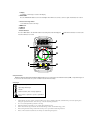
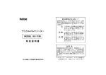
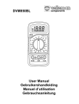
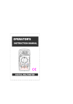
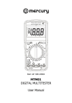
Instruction Manual for MAS830LH MAS830H MAS830BH MAS838H Series Digital Multimeter DIGITAL MULTIMETER Introduction The instrument of this series is a small hand-held 3 1/2 digital multimeter featuring stable, highly reliable and anti-drop performance. It is provided with a LCD display of 15 mm height for clear reading. The circuit design takes LSI double integral A/D converter as its core under the protection of an overload protection circuit, making it a superior and handy instrument. It can be used to measure DC and AC voltage, DC current, resistance, diodes, transistors, temperature and for in-circuit continuity test. Measurement features of the types of this series: Features MAS830LH MAS830H MAS830BH MAS838H Alternating Voltage measurement V~ Direct Voltage measurement V Direct current measurement A Resistance measurement Ω Diode measurement Temperature measurement ℃ Data hold Backlight On-off measurement 1. Display 3 1/2 digital, 15 mm height, 7 sections LCD display 2. BACKLIGHT Press the BACKLIGHT button to turn on the backlights which will last 5 seconds, to turn it on again, hit the button as needed. 3. Function and range switch Select different functions and range 4.VΩ ΩmA Jack 5.COM jack 6.10A Jack 7.Data hold button Press the HOLD button. The LCD will hold the last reading measured and display the , symbol. When the button is released, the instrument will return to normal. 1 7 2 3 6 5 4 Safety Information MAS830L, MAS830, MAS830B and MAS838 Digital Multimeters are designed based on IEC61010 600V (CAT To ensure the safe and accurate use, please read the instruction manual carefully. Ⅱ) and pollution degree 2. Safety Signs Important safety information. Read the manual High voltage with danger Ground Double Insulation (Class II safety equipment). Fuse must be replaced as per the specification herein. • The instrument can only be used in conjunction with the probe for the compliance with safety standards. If the probe needs replacing due to • Do not exceed the input limits specified for each range. • When the instrument is measuring, do not touch the input terminal not in use. • When a measurement range is uncertain, turn the function/range switch to the maximum range position. • Before turning the function/range switch, make sure the probe is open with the circuit being measured. • Before on-line resistance measurement, turn off all power and discharge all capacitors. damage, the replacement must be of the same type or the same electrical specifications. • Be careful when taking measurement of voltage higher than 60V DC/30V AC. Remember to keep your fingers behind the hand shield of the probe. • When measuring a TV set or switch power supply, watch for pulse in the circuit that may damage the multimeter • Before measuring any transistor, make sure the probe is not connected to any circuit being measured. • Before taking the measurement of voltage with the probe, make sure there is no electronic element connected to the test socket of the transistor. Maintenance Before removing the rear cover, disconnect the probe from the circuit to be measured To protect the internal circuit, replace the fuse with one of the same specification: • • F1 250mA/250V F2 10A/250V Don't use the instrument until the rear cover is placed back and the screws are tightened. Clean the housing of instrument only with a wet rag dripped with little detergent but never chemical solution. In case of any abnormality, stop using it and sent it for maintenance. • • Technical data Accuracy ±% of reading ± 5 digits, one year warranty. Ambient temperature: 18℃to 28℃, Ambient humidity: 80%. : General features: Maximum voltage between input and the ground Fuse Power Maximum display value Over-range indication Polarity display Operating temperature Storage temperature Low voltage indication Appearance dimension Weight :CATⅡ600V :F1 250mA/250V F2 10A/250V :9V battery,NEDA 1604 or 6F22 :1999 :“1” :“−”for negative polarity。 :0℃ to 40℃ :−10℃ to 50℃. :“ ”on the display :138mm×69mm×31mm :170g. Direct current voltage measurement Range Resolution Accuracy 200mV 100µV ±0.5% of reading ,± 3 digits 2V 1mV ±0.5% of reading ,± 3 digits 20V 10mV ±0.5% of reading ,± 3 digits 200V 100mV ±0.5% of reading ,± 3 digits 600V : 1V ±0.8% of reading, ± 5 digits 。 Overload protection 200mV range: 250V dc or rms; the rest ranges: 600V dc or rms Direct current measurement Range Resolution Accuracy 20µA 0.01µA ±1% of reading ,± 3 digits 200µA 0.1µA ±1% of reading , 2mA 1µA 3 digits ±1% of reading ,± 3 digits 20mA 10µA ±1% of reading ,± 5 digits 200mA 100µA ±1.5% of reading ,± 5 digits 10A 10mA ±3% of reading,± 10 digits Overload protection: F1 200mA/250V Fuse F2 10A/250V ∗ MAS838H, no 20µA position Alternating voltage measurement Range Resolution Accuracy 200V 100mV ±1.2 % of reading ,± 10 digits 600V 1V ±1.2 % of reading ,± 10 digits Overload protection: 600V dc or rms. 。 Frequency range: 40Hz to 400Hz Display: Average (effective value of sinusoid). Resistor Range Resolution Accuracy 200Ω 0.1Ω ±0.8% of reading,± 5 digits 2kΩ 1Ω ±0.8% of reading,± 2 digits 20kΩ 10Ω ±0.8% of reading,± 2 digits 200kΩ 100Ω ±0.8% of reading,± 2 digits 2MΩ 1kΩ ±1.0% of reading,± 5 digits Maximum open circuit voltage: 3.2V Overload protection: 250V DC or RMS. Diode and circuit on-off measurement Range Description When the on-resistance is smaller than (70±30)Ω, the built-in buzzer will beep. Displays the approximate diode positive voltage. Overload protection: 250V DC or RMS. AC. Temperature measurement Range Resolution 1℃ ℃ Measurement Accuracy -20℃ to 0℃ ±10%Range, ± 2 digits -0℃ to 400℃ ±1.0%Range,± 3 digits 400℃ to ±2.0%Range 1000℃ Instructions Notices before operation: 1. Plug the instrument in, check the 9V battery, if it is low, the symbol will display, requiring battery replacement; otherwise follow the steps below. 2. The besides the probe jack indicates that the input voltage or current should not exceed the specified limits to protect the internal circuit. 3. Before measurement, turn the function/range switch to the desired range. Direct voltage measurement 1. Insert the red probe into the “VΩmA” jack and the black one into the COM jack. 2. Turn the function/range switch to the range of V and connect the probe to the power supply or load to be measured. The polarity touched by the red probe will be on the display Notice 1. If you do not know the measured voltage range in advance, set the function/range switch to the maximum range, and then gradually turn to smaller ranges until satisfactory resolution. 2. If the display shows "1", this indicates an overrange measurement, and the switch should be set to a higher range. 3. Do not input a voltage of more than 600V, it is capable of indicating a higher voltage, but with the risk of damaging the inside circuit. When taking the measurement of high voltage, pay special attention to avoid an electric shock. 4. Direct current measurement 1. Place the black probe into the COM jack. for current to be measured not exceeding 200mA, put the red one into the "V.Ω.mA" jack. For current to be measured between 200mA and 10A, insert the red probe into the 10A jack 2. Set the function/range switch to the desired A range, and connect the probe in series with the load to be measured. The current value and the polarity connected to the red probe will be shown on the display. Notice 1. 2. 3. If you do not know the measured voltage range in advance, set the function/range switch to the maximum range, and then gradually turn to smaller ranges until satisfactory resolution. If the display shows "1", this indicates an overrange measurement, and the switch should be set to a higher range. The symbol beside the probe indicates the maximum input current is 200mA or 10A, depending on the inserted jack. Overcurrent will blow the fuse. Alternating voltage measurement 1. Place the red probe into the “VΩmA” jack and the black one into the “COM” jack. 2. Turn the switch to V~, and connect the probe to the power supply or load to be measured. :Refer to point 1, 2, 3, and 4 for direct current voltage measurement. Note Resistance measurement 1. Place the black probe into the COM jack and the red one into the V/Ω/Hz jack. 2. Turn the switch to the COM jack, and connect the probe to the resistor being measured and read the results on the display Notice 1. 2. 3. If the resistor being measured is greater than the maximum value of the selected range, the display will show “1”, requiring the selection of a higher range. It normally takes a few seconds for the reading to get stable when measuring a resistor larger than 1 MΩ. In default of input, for instance, open circuit, the display shows “1”. When measuring an online resistor, de-energized the circuit being measured and discharge all capacitors. Diode measurement 1. 2. Insert the black probe into the COM socket and the red one into the V.Ω.mA, then the red probe will be of positive polarity. Turn the switch to the range, and connect the red probe to the positive pole of the diode being measured and the black one to the negative pole, read the approximate forward voltage drop of the diode on the display. Circuit On-Off measurement Insert the black probe into the COM jack and the red one into the V.Ω.mA jack. Turn the switch to the position and connect the probes in parallel with two points of the circuit being measured. If the resistance between the two points is less than 100Ω, the built-in buzzer will beep to indicate the continuity between the two points. Temperature measurement Turn the switch to the ℃ position and insert the black probe of the thermocouple sensor into COM jack and the red one into the V.Ω.mA jack. Place the operating terminals (temperature measurement terminals) onto or inside the object being measured and directly read the temperature value in ℃ on the display. When the switch is turned to the ℃ position and the sensor is in an open circuit, the display shows room temperature. Replacement of battery and fuse 1. 2. 3. 4. Under normal conditions, it is unnecessary to replace the fuse. Don’t replace it until the probes are unplugged and the power is shut down. Take out the two screws of the rear cover to remove the housing. The specification of the fuse is: F1 250mA/250V, F210A/250V. The replacement should be of the same specification The battery for this multimeter is 9V NEDA 1604 or 6F22. The replacement should be of the same specification Don’t put the instrument into use until the rear cover is screwed after replacing battery or fuse. Warning To avoid electric shock, make sure the probes are disconnected from the measured circuit before removing the rear cover. Make sure the rear cover is tightly screwed before using the instrument.