1
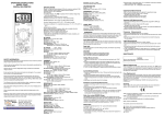
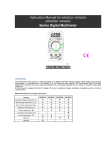
Item ref: 600.100UK MTM01 DIGITAL MULTITESTER User Manual Please read this manual thoroughly and ensure all contents are fully understood before using the apparatus. Warning To avoid possible electric shock or personal injury, and to avoid possible damage to the tester or to the equipment under test, adhere to these following rules: Before using the tester inspect the case. Do not use the tester if it is damaged or the case (or part of the case) is removed. Look for cracks or missing plastic. Pay attention to the insulation around the connectors. Inspect the test leads for damaged insulation or exposed metal. Check the test leads for continuity. Do not apply more than the rated voltage, as marked on the tester, between the terminals or between any terminal and grounding. The rotary switch should be in the right position and no changeover of range shall be made while measurement is conducted to prevent damage. When the tester is working at an effective voltage over 60V in DC or 30Vrms in AC, special care should be taken for there is danger of electric shock. Use the proper terminals, function, and range for your measurements. Do not use or store the tester in an environment of high temperature, humidity, explosive, flammable, damp or of a strong magnetic field. The performance of the tester may deteriorate after being exposed to any of these elements. When using the test leads, keep your fingers behind the finger guards. Disconnect circuit power and discharge all high-voltage capacitors before testing resistance, continuity, diodes. MTM01 User Manual Replace the battery as soon as the battery indicator appears. With a low battery, the meter may produce false readings that can lead to electric shock and personal injury. Remove the connection between the testing leads and the circuit being tested, and turn the meter power off before opening the meter case. The internal circuit of the meter shall not be altered at will to avoid damage of the meter and any accident. A soft cloth and mild detergent should be used to clean the surface of the tester on a regular basis. No abrasive and solvent should be used to prevent the surface of the tester from corrosion or damage. The tester is suitable for indoor use only. Turn the tester power off when it is not in use and take out the battery when not using for a long time. Check the battery regularly; replace the battery immediately if any signs of leaking appear. Battery acid will damage the tester. General Specifications Max display: Polarity: Measure method: Sampling speed: Over-load indication: Operating Environment: Storage Environment: Power: Low battery indication: Dimensions: Weight: LCD (1999 count) 67 x 42mm Automatic, indicated minus, assumed plus double integral A/D switch implement 2 times per second “1” is displayed 0ºC-40ºC, at <80%RH -10ºC-50ºC, at <85%RH 9Vdc (1 x PP3 battery supplied) “ ” 190 x 90 x 33mm 190g (including battery) MTM01 User Manual LCD Power Button HOLD Button Range switch A/mA terminal 10A terminal COM terminal VΩ terminal Multi-function adapter MTM01 User Manual Multitester comparison table Model MTP01 DCV Y ACV Y DCA Y ACA Y Ω Y Y Y hFE Y Cap Y Technical Specifications Accuracies are guaranteed for 1 year, 23ºC ± 5ºC, less than 80% RH. DC Voltage RANGE 200mV 2V 20V 200V 600V RESOLUTION 100uV 1mV 10mV 100mV 1V ACCURACY ± (0.5% of rdg + 3D) ± (0.8% of rdg + 5D) ± (1.0% of rdg + 5D) Input Impedance: 10MΩ Overload Protection: 1000V DC or 750V AC rms Max. Input voltage: 1000V DC AC Voltage RANGE 200V 500V RESOLUTION 100mV 1V ACCURACY ± (2.0% of rdg + 10D) ± (2.0% of rdg + 10D) Input Impedance: 10MΩ Frequency Range: 40Hz ~ 400Hz Overload Protection: 1000V DC or 750V AC rms Response: Average, calibrated in rms of sine wave Max. Input voltage: 750V AC rms MTM01 User Manual Audible Continuity RANGE DESCRIPTION Built-in buzzer sounds if resistance is less than 30±20Ω The approximate forward voltage drop will be displayed Overload Protection: 250V DC/AC rms Remark Open circuit voltage: about 2.8V Open circuit voltage: about 2.8V DC Current RANGE RESOLUTION 2mA 1uA 20mA 10uA 200mA 100uA 10A 10mA Overload Protection: mA: F0.5A/600V fuse 10A: F10A/600V fuse Voltage Drop: 200mV ACCURACY ± (1.8% of rdg + 2D) ± (2.0% of rdg + 2D) ± (2.0% of rdg + 10D) AC Current RANGE RESOLUTION ACCURACY 2mA 1uA ± (2.0% of rdg + 2D) 20mA 10uA 200mA 100uA ± (2.0% of rdg + 2D) 10A 10mA ± (2.5 of rdg + 10D) Overload Protection: mA: F0.5A/600V fuse (DT9205A, DT9207A, DT9208A) 10A: F10A/600V fuse Voltage Drop: 200mV Frequency Range: 40Hz ~ 400Hz Response: Average, calibrated in rms of sine wave MTM01 User Manual Resistance RANGE 200Ω 2KΩ 20kΩ 200kΩ 2MΩ 20MΩ 200MΩ RESOLUTION 0.1Ω 1Ω 10Ω 100Ω 1kΩ 10kΩ 100kΩ ACCURACY ± (1.0% of rdg + 10D) ± (1.0% of rdg + 4D) ± (1.0% of rdg + 10D) ± [5%*(rdg-10) + 10D) Open Circuit Voltage: about 3V Overload Protection: 250V DC/AC rms Capacitance RANGE 2nF 20nF 200nF 2uF 20uF RESOLUTION 1pF 10pF 100pF 1nF 10nF ACCURACY ± (4.0% of rdg + 5D) Overload Protection: F0.5A/600V fuse Over-load protect: 250V DC/AC rms MTM01 User Manual OPERATING INSTRUCTIONS VOLTAGE MEASUREMENT 1. Connect red test lead to “VΩ” jack, black lead to “COM” jack. 2. Set RANGE switch to desired VOLTAGE position, if the voltage to be measured is not known beforehand, set switch to the highest range and reduce it until satisfactory reading is obtained. 3. Connect test leads to device or circuit being measured. 4. Turn on power of the device or circuit being measured voltage value will appear on Digital Display along with the voltage polarity. Please note: In small range, the meter may display an unstable reading when the test leads have not been connected to the load to be measured. It is normal and will not affect the measurements. When the meter shows the over range symbol “1”, a higher range must to be selected. To avoid damage to the meter, don’t measure a voltage which exceeds 600Vdc (for DC voltage measurement) or 600Vac (for AC voltage measurement). CURRENT MEASUREMENT 1. For reading less than 200mA connect red lead to “mA” and black lead to “COM” (for measurements between 200mA and 10A, connect red lead to “10A”) ensure jacks are fully depressed. MTM01 User Manual 2. Set the range switch to desired AC or DC position. If the current magnitude to be measured is not known beforehand, set the ranges switch to the highest range position and then reduce it range by range until satisfactory resolution is obtained. 3. Open the circuit to be measured, and connect test leads in SERIES with the load in with current is to measure. 4. Current reading will be displayed on LCD, for DC current measurement, the polarity of the red probe will also be indicated. Please note: When the display shows the over range symbol “1”, a higher range must be selected. In addition “10A” function is designed for intermittent use only. RESISTANCE MEASUREMENT 1. Connect red lead to “VΩ”, black lead to “COM”. 2. Set the range switch to desired Ω range. 3. If the resistance being measured is connected to a circuit, turn off power and discharge all capacitors before measurement. 4. Connect test leads to circuit being measured. 5. Read resistance value on Digital Display. Please note: For resistance measurements >1MΩ, the meter may take a few seconds to stabilize reading. This is normal for high-resistance measurement. When the input is not connected, i.e. at open circuit, the symbol “1” will be displayed as an over range indicator. MTM01 User Manual CAPACITY MEASUREMENT 1. Connect the BLACK test lead to the COM jack and the RED to the mA jack. 2. Set the Range switch at F position. (NOTE: The polarity of the RED lead is positive “+”) 3. Connect test leads across the capacitor under measure and be sure the polarity of connection is observed. Please Note: To avoid damage to the Meter, disconnect circuit power and discharge all high-voltage capacitors before measuring capacitance. The tested capacitor should be discharged before the testing procedure. Never apply voltage to the input, or serious damage may result. CONTINUITY TEST 1. 2. 3. 4. Connect the BLACK test lead to the “COM” jack and the RED to the “VΩ” jack (Note: The polarity of the red test lead is positive “+”). Set the range switch to range Connect the test leads across the load to be measured. If the circuit resistance is lower than about 30±20Ω, the builtin buzzer will sound. DIODE MEASUREMENT 1. Connect red lead to “VΩmA”, black lead to “COM”. 2. Set RANGE switch to “ ” position. 3. Connect the red test lead to the anode of the diode to be measured and black test lead to cathode. MTM01 User Manual 4. The meter will show the approximate forward voltage of the diode. If the connections are reversed, “1” will be shown on the display. TRANSISTOR hFE MEASUREMENT 1. 2. 3. 4. Set the range switch to hFE range. Connect the adapter to the “COM” jack and the “hFE” jack. Don’t reverse the connection. Identify whether the transistor is NPN or PNP type and locate Emitter, Base and Collector lead. Insert the leads of the transistor to be tested into the proper holes of the transistor test socket of the adaptor. LCD display will show the approximate hFE value. BATTERY AND FUSE REPLACEMENT 1) Battery and fuse replacement should only be done after the test leads have been disconnected and power is off. 2) Loosen screws with suitable screwdriver and remove case bottom. 3) The meter is powered by a single 9V PP3 battery. Snap the battery connector leads to the terminals of a new battery and reinsert the battery into the case top. Dress the battery leads so that they will not be pinched between the case bottom and case top. 4) The meter is protected by fuse: A) mA: F0.5A/600V Fast, Breaking capacity is 10KA, dimensions are 20 x 5mmØ . B) 10A: F10A/600V Fast, Breaking capacity is 10KA, dimensions are 20 x 5mmØ . MTM01 User Manual Replace the case bottom and reinstall the three screws. Never operate the meter unless the case bottom is fully closed. ACCESSORIES Instruction manual Set of test leads (red and black) 9V PP3 battery EN61010–1:2010 This product is classed as Electrical or Electronic equipment and should not be disposed with other household or commercial waste at the end of its useful life. The goods must be disposed of according to your local council guidelines. Errors and omissions excepted. Copyright© 2014. AVSL Group Ltd. MTM01 User Manual