1
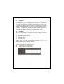
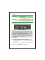
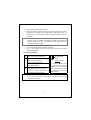
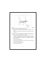
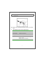
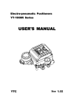
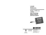
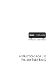
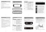
Trademarks Copyright PLANET Technology Corp. 2002. Contents subject to revision without prior notice. PLANET is a registered trademark of PLANET Technology Corp. All other trademarks belong to their respective owners. FCC Warning This equipment has been tested and found to comply with the limits for a Class A digital device, pursuant to Part 15 of the FCC Rules. These limits are designed to provide reasonable protection against harmful interference when the equipment is operated in a commercial environment. This equipment generates, uses, and can radiate radio frequency energy and, if not installed and used in accordance with the Instruction manual, may cause harmful interference to radio communications. Operation of this equipment in a residential area is likely to cause harmful interference in which case the user will be required to correct the interference at his own expense. CE Mark Warning This is a Class A product. In a domestic environment, this product may cause radio interference, in which case the user may be required to take adequate measures. Revision PLANET Media Converter Chassis User's Manual FOR MODELS: MC-1000R Part No.: 2010-000008-001 2 1. Overview The 19-inch Media Converter Chassis, MC-1000R is designed to accommodate 10 units of various type media converter at a central location for multiple segments cross connection. Independent power supply in each bay of the MC-1000R, you can freely install the converters without interrupting the rest of networks. Moreover, each bay of the media center can deploy to PLANET’S converter family like Ethernet, Fast Ethernet twisted pair to Fiber-optic conversion, Gigabit SX to LX conversion, etc…, The slide-in media converters are available for use at 19-inch Media Converter Chassis. 2. Checklist Before you start installing the Converter, verify that the package contains the following: The Media Converter Chassis Mounting Accessory (for 19" Chassis Shelf) This User's Manual AC Power Cord Please notify your sales representative immediately if any of the above-mentioned items is missing or damaged 3. Panel Description The front panel of the MC-1000R is as below: 10 open slots for media converters 3 LED indicators for system and fans Fig. 1 Front View of 19-inch Converter Chassis MC-1000R 3 LED indications: Printing PWR LED Status ON OFF FAN A / FAN B ON OFF Description The chassis is powered The chassis is not powered or power failure if the AC outlet is with 100~240V AC voltage. Please consult your local dealer if power failure. The fan is functional O.K The fan is not powered or it is malfunction. If the fan LED remains off while power is on. Please consult your local dealer to replace the FAN. The rear panel of the MC-1000R is with two fans, one ON/OFF Switch and a power inlet that accept 100~240V AC, 50/60Hz power input. Fig. 2 Rear view of MC-1000R Power Notice: 1. The device is a power-required device, it means, it will not work till it is powered. If your networks should active all the time, please consider use an UPS (Uninterrupted Power Supply) for your device. It will prevent you from network data loss or network downtime. 2. In some area, installing a surge suppression device may also help to protect your chassis from being damaged by unregulated surge or current to the converter or the power adapter. 4. Installation 4.1 Install Media Converter Chassis to 19-inch Wiring Closet Rack » Install four screws through mounting ears into each side » Locate Converter Chassis at 19-inch mounting rails and screw up the » front brackets Set Main power switch at "OFF" position before connecting the power cord. 4.2 Install Converters to the Media Converter Chassis 4 » » Turn off the Converter Chassis power Verify the Media Converter is right for this Chassis and locate +5VDC power jack on converter back, carefully slide in and plug to match 19" Chassis slot +5V DC receptacle. Push up the picket fence to lock the converters Note: The slide-in Media Converters and Converter Chassis should be supplied only from PLANET, both Media Converters and Chassis are built to match each other at dimensions, DC power jack, DC receptacle and power safety. » » » Ensure that there is no activity in the network Connect the media cable for network connection Turn on the chassis power, the Power LED, and both FAN LED indicators will light up Converter Check point Fiber Attach the fiber cable. The Tx, Rx fiber 2.5mm Port cable must be paired at both ends DC Receptacle TP 2.5mm Attach UTP Cat. 3 or 5 cable to TP port +5V for each slot Port MPR: To a Hub or Repeater DTE: To a workstation or NIC Slide switch "DTE"/"MPR" is on the side DC receptacle is 2.5mm wide that conforms to and matches panel. Default: MPR BNC Attach T-Connector to BNC port and the Media Converter 2.5mm DC jack's central post. Do not install Port connect the RG-58 coaxial network. Ensure the coaxial cable/segment is any improper unit, model of the terminated at both ends properly. Note: Media Converter For safety reason, it is recommend storing the AC adapter of the converter in a known secured place. For more about converter, refer to the user guide of the converter. 5 Fig. 3 Installing Media Converter Chassis in 19-inch Wiring Closet Rails 4.3 Install power to the Media Converter Chassis » Plug in the power cord to the Media Converter Chassis and turn on the » device Check the correct LED status of PWR, FAN A, FAN B is light on with green LED 4.4 Install / remove redundant power to the Media Converter Chassis » Remove the cover of power supply on front panel » To install the redundant power to MC-1000R, carefully, push the power to make it connected firmly, once the power installed, turn on the I/O switch. The LED indicator should turn on to indicate the redundant power is operating. » Put the cover of chassis back » To remove the redundant power from the power slot, please be sure the other power is working properly » Pull out the power you want to remove » Put the cover of chassis back 6 Note: Push the latch to right side (see Figure 4) when install or remove the redundant power Fig.4 Push the latch to right side when install or remove the redundant power 5. MC-1000R Converter Chassis Specifications Dimension Converter slots Power Input Power Dissipation Power Output per slot DC Plug per slot LED indication Environment Emission 440 mm x 125 mm x 220 mm (WxHxD) 10 slots 100~240V AC, 50/60Hz 100 watts / one power unit +5V DC 2.5 mm DC receptacle 3; Power, FAN A, FAN B Temperature: 0 ~ 50 degree C (operating), -20~70 degree C (storage) Humidity: 0~90% non-condensing FCC, CE-mark 7 2010-000008-001