1
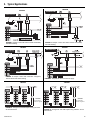
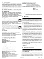
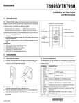
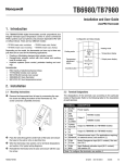
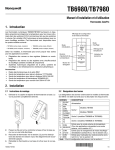
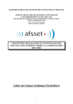
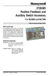
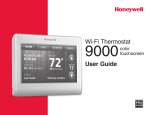
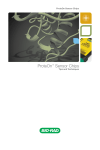
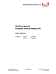
TB6980/TB7980 Installation and User Guide ZonePRO Thermostats 1. Introduction The TB6980/TB7980 digital thermostats provide proportional plus integral individual space temperature control in zoned commercial HVAC systems such as hydronic and pressure dependent VAV with or without reheat. There are four different models: • TB7980A (single output, modulating) • TB6980A (single output, floating) • TB7980B (multiple output modulating) • TB6980B (multiple output, floating) Configuration and status display Heating mode Cooling mode Temperature display Depending on the models, the thermostat can have up to three outputs for the following applications: Floating or Modulating damper/valve actuator control Damper/valve actuator control with duct reheat and auxiliary heat (B models only) Hydronic systems (room control, perimeter heating and cooling) Output power display Temperature adjustment button Override button Accessories R841 family of electromechanical relays T7770A3002 remote room sensor 50014156-002 remote room sensor 32004800-001 bare thermistor 50014157-001 duct temperature sensor 2. Installation 2.1 Mounting Instructions 2.2 Terminal Designations 1. The designations of the terminals vary according to the particular model of thermostat. Refer to the following table for the description of each terminal. 2. 3. 4. Remove the thermostat from its base by unscrewing the captive screw and tilting the bottom of the thermostat up. The screw cannot be completely removed. Pass the wires through the center hole of the base and secure the base to the wall or onto an electrical box. Wire the thermostat. See section 2.2 for terminal designations and section 3 for typical wiring diagrams. Reinstall the thermostat onto its base and secure with the captive screw. TB6980/TB7980 TERMINAL DESCRIPTION 1 2 24 VAC COM Power supply 3 4 AN1 COM 3 4 OPEN CLOSED 5 6 T2/AN2 T2/COM Output 2 (TB6980B and TB7980B models) 7 8 T3 T3 Output 3 (TB6980B and TB7980B models) TB7980 models Output 1 TB6980 models 9 COM External sensor input. (For applications requiring 10 SENSOR an external sensor, see section 4.2.) 9 COM 11 C-Over Mode Changeover input (N.O. contact). See section 5.5.2. 9 COM 12 NSB Night Setback activation input (N.O. contact). See section 5.6. Note: To configure the terminals, see section 4. 1/6 3. Typical Applications TB6980B TB7980B FIGURE 1: Damper control with electric reheat and auxiliary baseboard heating. TB6980B TB7980B FIGURE 3: Damper control with automatic changeover, electric reheat and central cooling FIGURE 4: Temperature control of fresh air supply TB7980B TB7980B CAUTION Do not connect common to ground FIGURE 5: Changeover and NSB inputs sharing the same 24-Vac transformer TB6980/TB7980 FIGURE 2: Damper control with electric reheat and auxiliary hot-water heating CAUTION Do not connect common to ground FIGURE 6: Changeover and NSB inputs using different 24-Vac transformers 2/6 4. Configuration 4.1 Configuration Menus (See following pages for explanations) NOTE: Factory settings are inside the shaded cells. 1. TB7980A model 2. Application (section 4.2) 0 1 2 3 4 5 Internal sensor Room Return Supply Auto changeover Limited cooling Default mode & Output 1 type (section 4.3.1) 0 Cool / 0-10V 1 Heat / 0-10 V 2 Cool / 2-10 V 3 Heat / 2-10 V NSB value (section 5.6) 1 2 3 4 5 6 7 8 9 2°F (1°C) 4°F (2°C) 6°F (3°C) 8°F (4°C) 10°F (5°C) 12°F (6°C) 14°F (7°C) 16°F (8°C) 18°F (9°C) 0 1 2 3 4 5 Output 1 min. opening (section 4.3.2) 0% 10% 20% 30% 40% 50% Maximum setpoint (section 4.6) Minimum setpoint (section 4.6) Can be set between 95°F (35°C) and ’’minimum setpoint + 1’’ Can be set between 50°F (10°C) and ’’maximum setpoint - 1’’ Default value is 95°F (35°C) Default value is 50°F (10°C) 3. 4. 5. 6. Remove the thermostat from its base and set the SW2 switch to MENU. Reinstall the thermostat. The thermostat is now in configuration mode. The first digit flashes to indicate that the first item of the menu can now be modified. To modify the setting, use the up/down arrows. Refer to the adjacent tables. Press Override to save the new setting and go to the next item. Repeat steps 3 and 4 for remaining items. When the configuration is done, set the SW2 switch back to NORMAL. TB6980A model Application (section 4.2) 0 1 2 3 4 5 Internal sensor Room Return Supply Auto changeover Limited cooling Default mode (section 4.3.1) 0 1 NSB value (section 5.6) Cool Heat 1 2 3 4 5 6 7 8 9 2°F (1°C) 4°F (2°C) 6°F (3°C) 8°F (4°C) 10°F (5°C) 12°F (6°C) 14°F (7°C) 16°F (8°C) 18°F (9°C) 0 1 2 3 4 5 Output 1 min. opening (section 4.3.2) 0% 10% 20% 30% 40% 50% 0 1 2 3 4 5 6 7 8 Output 1 opening time (section 4.3.3) 80 90 100 110 120 130 140 150 160 Maximum setpoint (section 4.6) Minimum setpoint (section 4.6) Can be set between 95°F (35°C) and ’’minimum setpoint + 1’’ Can be set between 50°F (10°C) and ’’maximum setpoint - 1’’ Default value is 95°F (35°C) Default value is 50°F (10°C) ABBREVIATIONS NSB - Night setback (number of degrees the thermostat will be set back upon receiving a setback signal) SSR - Solid state relay (used with fast cycling electric heaters, SSR's are a quiet alternative to electromechanical relays. They're typically included with electric duct reheat equipment) SCR - Silicon controlled rectifier (similar to an SSR, SCR's are also quiet and capable of switching very high current. If used, they're usually included with the equipment) N.C. - Normally closed N.O. - Normally open TB7980B model Application (section 4.2) 0 1 2 3 4 5 a. Internal sensor Room Return Supply Auto changeover Limited cooling Default mode & Output 1 type (section 4.3.1) 0 Cool / 0-10V 1 Heat / 0-10 V 2 Cool / 2-10 V 3 Heat / 2-10 V Output 2 typea (section 4.4) 0 1 2 3 4 5 6 7 8 Output 3 type (section 4.5) Not used SSR 24 VAC N.C. Valve N.O. Valve Mech. relay SSR 3-32 V SCR 0-10 V Act. 0-10 V Act. / 2-10 V 0 1 2 3 4 5 Not used SSR 24 VAC N.C. Valve N.O. Valve Mech. relay Contact 0 1 2 3 4 5 6 7 8 9 Output 3 activation (section 4.5) 100% 10% 20% 30% 40% 50% 60% 70% 80% 90% NSB value (section 5.6) 1 2 3 4 5 6 7 8 9 2°F (1°C) 4°F (2°C) 6°F (3°C) 8°F (4°C) 10°F (5°C) 12°F (6°C) 14°F (7°C) 16°F (8°C) 18°F (9°C) 0 1 2 3 4 5 Output 1 min. opening (section 4.3.2) 0% 10% 20% 30% 40% 50% Maximum setpoint (section 4.6) Minimum setpoint (section 4.6) Can be set between 95°F (35°C) and ’’minimum setpoint + 1’’ Can be set between 50°F (10°C) and ’’maximum setpoint - 1’’ Default value is 95°F (35°C) Default value is 50°F (10°C) If Output 2 type is set to 0-4, set the SW6 switch to Triac. If the output type is set to 5-8, set the switch to Analog (see section 4.7). TB6980B model Application (section 4.2) 0 1 2 3 4 5 a. Internal sensor Room Return Supply Auto changeover Limited cooling Output 2 typea (section 4.4) Default mode (section 4.3.1) 0 1 Cool Heat 0 1 2 3 4 5 6 7 8 Not used SSR 24 VAC N.C. Valve N.O. Valve Mech. relay SSR 3-32 V SCR 0-10 V Act. 0-10 V Act. / 2-10 V Output 3 type (section 4.5) 0 1 2 3 4 5 Not used SSR 24 VAC N.C. Valve N.O. Valve Mech. relay Contact Output 3 activation (section 4.5) 0 100% 1 10% 2 20% 3 30% 4 40% 5 50% 6 60% 7 70% 8 80% 9 90% NSB value (section 5.6) 1 2 3 4 5 6 7 8 9 2°F (1°C) 4°F (2°C) 6°F (3°C) 8°F (4°C) 10°F (5°C) 12°F (6°C) 14°F (7°C) 16°F (8°C) 18°F (9°C) 0 1 2 3 4 5 Output 1 min. opening (section 4.3.2) 0% 10% 20% 30% 40% 50% Output 1 opening time (section 4.3.3) 0 80 1 90 2 100 3 110 4 120 5 130 6 140 7 150 8 160 Maximum setpoint (section 4.6) Minimum setpoint (section 4.6) Can be set between 95°F (35°C) and ’’minimum setpoint + 1’’ Can be set between 50°F (10°C) and ’’maximum setpoint - 1’’ Default value is 95°F (35°C) Default value is 50°F (10°C) If Output 2 type is set to 0-4, set the SW6 switch to Triac. If the output type is set to 5-8, set the switch to Analog (see section 4.7). TB6980/TB7980 3/6 4.2 Application Types The following table shows the different thermostat applications and their corresponding settings in the configuration menu. Menu setting 0 1 Description Internal sensor To control the ambient temperature using the internal (built-in) sensor Room To control the ambient temperature using the 50014156-002 temperature sensor (the internal sensor is not used) Air return To control the temperature at the air return using the 50014157-001 temperature sensor (the internal sensor is not used) 3 Air supply To control the temperature at the fresh air supply using the 50014157-001 temperature sensor (the internal sensor is not used) 4 Automatic changeover To control the ambient temperature using the internal sensor. The 50014157-001 temperature sensor is used for automatic changeover. See section 5.5.1. Limited cooling To use the outdoor air for cooling whenever possible. The 50014157-001 temperature sensor is used to measure the outdoor air temperature. The internal temperature sensor measures the room temperature which is then compared with the setpoint. If the room temperature is lower than the setpoint, the air intake damper remains closed. If the room temperature is higher than the setpoint, the latter is then compared with the outdoor temperature. If the fresh air temperature is lower than the setpoint by more than 5°F(3°C), the damper opens to allow cool air in. 2 5 The following table shows the different default modes, the different output types for Output 1, and their corresponding settings in the configuration menu. Menu setting TB7980 models TB6980 models 0 Cool / 0-10 V analog (max. of 10 min. refresh) Cool (24 V tri-state floating) 1 Heat / 0-10 V analog (max. of 10 min. refresh) Heat (24 V tri-state floating) 2 Cool / 2-10 V analog (max. of 10 min. refresh) 3 Heat / 2-10 V analog (max. of 10 min. refresh) 4.3.2 Minimum Opening The minimum damper opening can be set between 0 and 50 %. Note: It is not recommended to set the minimum damper opening to 0 % (fully closed) when a duct heater is connected to Output 2 or 3. 4.3.3 Opening time (TB6980 models only) The damper opening time can be set between 80 and 160 seconds. 4.4 Output 2 (models TB6980B and TB7980B) Output 2 controls heating only, regardless of the thermostat’s mode. When the thermostat is in heat mode, Output 2 is activated as soon as Output 1 reaches its full capacity. When the thermostat is in cool mode, Output 2 is activated when the measured temperature drops below the setpoint. 4.3 Output 1 Output 1 is used to control a damper. It controls heating when the thermostat is in heat mode or cooling when the thermostat is in cool mode. The following table shows the output types for Output 2 and their corresponding settings in the configuration menu. Menu setting Set the following configuration parameters: • • • • Default mode Output type (TB7980 models only) Minimum opening Opening time (TB6980 models only) 4.3.1 Default Mode / Output Type The default mode (heat/cool) is used for the following: • The default mode is the thermostat’s mode at power-up. • The default mode is the active mode when the N.O. changeover contact is open (see section 5.5.2). • When configured as a contact (see section 4.5), Output 3 controls either heating or cooling depending on whether the default mode is set to heat or cool respectively. TB6980/TB7980 Description 0 Not used 1 24 VAC pulsed (triac) / 1 sec. cycle 2 24 VAC pulsed (triac) / 10 min. cycle / direct action (e.g., N.C. thermal valve) 3 24 VAC pulsed (triac) / 10 min. cycle / reverse action (e.g., N.O. thermal valve) 4 24 VAC pulsed (triac) / 15 min. cycle (e.g., mechanical relay such as R841) 5 0-10 V pulsed / 1 sec. cycle 6 0-10 V analog / 1 sec. refresh (e.g., SCR controlled device such as a re-heater) 7 0-10 V analog / max. of 10 min. refresh (e.g., valve) 8 2-10 V analog / max. of 10 min. refresh (e.g., damper) Note: If 0-4 is selected, set the SW6 switch to Triac. If 5-8 is selected, set the switch to Analog (see section 4.7) 4/6 4.5 Output 3 (models TB6980B and TB7980B) 4.7 DIP Switches The following table shows the output types for Output 3 and their corresponding settings in the configuration menu. Three switches at the back of the control module are used to select various options. Temperature Display (SW1) Menu setting Description Selects the desired temperature display (°C or °F). 0 Not used Access Mode (SW2) 1 24 VAC pulsed (triac) / 1 sec. cycle 2 24 VAC pulsed (triac) / 10 min. cycle / direct action (e.g., N.C. thermal valve) Selects the operation mode (NORM) or the configuration mode (MENU). 3 24 VAC pulsed (triac) / 10 min. cycle / reverse action (e.g., N.O. thermal valve) 4 24 VAC pulsed (triac) / 15 min. cycle (e.g., mechanical relay such as R841) 5 N.O. contact (The contact closes when Output 1 reaches or exceeds set percentage. See section 4.1.) When any setting between 1 and 4 is selected, Output 3 controls heating only, regardless of the thermostat’s mode. • Place the switch to MENU to access the configuration menu. • Place the switch to NORM for normal display. Output 2 Type (SW6) Sets Output 2 type (Analog or Triac). WARNING: Place the switch according to the type of device (Analog or Triac) connected to Output 2. Failure to do so can result in thermostat damage. 5.Operation 5.1 Power-Up Upon power-up, the thermostat undergoes a series of test before displaying the actual temperature. Note: On the TB6980A and TB6980B models, at power-up, the message OPEN appears at the top of the screen during the calibration of the damper opening. This can last up to 3 minutes. 5.2 Backlight When setting 5 is selected, Output 3 controls heating or cooling depending on whether the default mode has been set to heat or cool respectively (see section 4.3.1). For example, if the default mode has been set to heat mode, the contact remains opened when the thermostat is in cool mode. When the thermostat is in heat mode, the contact closes when Output 1 reaches a percentage of its capacity, set via the configuration menu. To turn the backlight on, press any button. The display will illuminate for 12 seconds. 5.3 Temperature Display and Setting The thermostat usually displays the actual temperature. To view the setpoint, press once on one of the buttons. The setpoint appears for 5 seconds and is indicated by the display. During the setpoint display, press one of the buttons to change it. Note: The temperature setpoint is automatically increased or decreased by 2°F (1°C) when the controller switches to heating mode or to cooling mode respectively. For example, if the setpoint is at 77°F (25°C) in heating mode, it will become 79°F (26°C) in cooling mode and will return to 77°F (25°C) when the controller is back in heating mode. 5.4 Output Display The bar graph represents the voltage for an analog output or the duty cycle for a triac output. The bar graph usually shows Output 1 power (% of damper opening). 4.6 Minimum and Maximum Setpoints The minimum and maximum setpoints are factory-set at 50°F (10°C) and 95°F (35°C). The maximum setpoint can be set between 95°F (35°C) and “minimum setpoint + 1”. The minimum setpoint can be set between 50°F (10°C) and “maximum setpoint - 1”. To view Output 2 or 3, press Override for 2 seconds to enter the diagnostic mode. Press Override momentarily to switch between the three output graphs. To exit the diagnostic mode, press Override for 2 seconds or wait for 1 minute for the mode to exit automatically. 5.5 Mode Changeover The thermostat can switch between heat mode and cool mode either via: • the automatic changeover • the changeover input TB6980/TB7980 5/6 5.5.1 Automatic changeover In automatic changeover, the thermostat detects when the system switches between heat mode and cool mode by comparing the air supply temperature with the ambient temperature. If the thermostat is in heat mode, it switches to cool mode when the air supply is cooler than ambient by 9°F (5°C) or more. If it is in cool mode, it switches to heat mode when the air supply is warmer than ambient by 9°F (5°C) or more. Note: Neither the heat mode icon ( ) nor cool mode icon ( ) appears when the thermostat is placed in automatic changeover. 5.5.2 Changeover Input The thermostat is in the default mode when the contact between terminals 9 and 11 is open and switches mode when the contact is closed. The default mode is set via the configuration menu. Note: The changeover contact state is ignored if the thermostat is configured in automatic changeover or in limited cooling. 5.6 Night Setback The Night Setback (NSB) mode is activated when the contact between terminals 9 and 12 is closed. When the thermostat is in the NSB mode, indicated by the ECONO display, the temperature is lowered or raised by the set NSB value depending whether the thermostat is in heat mode or cool mode respectively. The NSB value is set via the configuration menu. Night Setback Override To temporarily override the NSB mode, press the Override button. The NSB mode is lifted for the next 2 hours or until the Override button is pressed again. During the override, the normal setpoint is used and OVERRIDE is displayed. 5.7 Error Codes The following error codes can appear at the top of the display. E1: The internal temperature sensor is defective E2: The internal temperature sensor is shorted E3: The external temperature sensor is defective or not connected E4: The external temperature sensor is shorted 6. Technical Specifications Power: 24 VAC Current consumption: 25 mA Output signals: Depends on output configurations Output ratings: - Triac output: 0.5 A maximum @ 24 VAC - Analog output (SCR connection): 0 - 10 V, 10kΩ minimum - Analog output (SSR connection): 0 - 10 V, 45 mA maximum Setpoint range: 50°F to 95°F (10°C to 35°C) Temperature display: 32°F to 140°F(0°C to 60°C) Temperature display resolution: 1°F (0.5°C) Mode hysteresis: 4°F (2°C) Automatic changeover deadband: 9°F (5°C) Duty cycle: Depends on output configurations NSB offset: Programmable 2°F to 18°F (1°C to 9°C) NSB override period: 2 hours Memory protection: Configuration and setpoint Temperature control: Proportional integral adaptive (P.I.A.) Operating temperature: 32°F to 140°F (0°C to 60°C) Storage temperature: -4°F to 122°F (-20°C to 50°C) TB6980/TB7980 Humidity limits: 0 to 95% R.H., non-condensing Dimensions: 2.7 x 4.6 x 1.0 in. (69 x 118 x 27 mm) Accessories: - R841 electromechanical relay - 50014157-001 air duct temperature sensor - 50014156-002 remote room temperature sensor Compatible Damper/Valve actuators: VC6930, VC6934, VC6936 VC7930, VC7934, VC7936 ML6984 ML7984 ML6410, ML7410 ML6161B2024, MN6105A1011 ML7161A2008, MN7505A2001 Wiring: 18 AWG (1 mm2) wire Mounting: - directly to drywall - single-gang NEMA standard 2-in x 4-in electrical box - double-gang NEMA standard electrical box with mounting plate 7. Warranty Honeywell warrants this product, excluding battery, to be free from defects in the workmanship or materials, under normal use and service, for a period of two (2) years from the date of purchase by the consumer. If at any time during the warranty period the product is determined to be defective or malfunctions, Honeywell shall repair or replace it (at Honeywell's option). If the product is defective, (i) return it, with a bill of sale or other dated proof of purchase, to the place from which you purchased it, or (ii) call Honeywell Customer Care at 1-800-468-1502. Customer Care will make the determination whether the product should be returned to the following address: Honeywell Return Goods, Dock 4 MN10-3860, 1885 Douglas Dr N, Golden Valley, MN 55422, or whether a replacement product can be sent to you. This warranty does not cover removal or reinstallation costs. This warranty shall not apply if it is shown by Honeywell that the defect or malfunction was caused by damage which occurred while the product was in the possession of a consumer. Honeywell's sole responsibility shall be to repair or replace the product within the terms stated above. HONEYWELL SHALL NOT BE LIABLE FOR ANY LOSS OR DAMAGE OF ANY KIND, INCLUDING ANY INCIDENTAL OR CONSEQUENTIAL DAMAGES RESULTING, DIRECTLY OR INDIRECTLY, FROM ANY BREACH OF ANY WARRANTY, EXPRESS OR IMPLIED, OR ANY OTHER FAILURE OF THIS PRODUCT. Some states do not allow the exclusion or limitation of incidental or consequential damages, so this limitation may not apply to you. THIS WARRANTY IS THE ONLY EXPRESS WARRANTY HONEYWELL MAKES ON THIS PRODUCT. THE DURATION OF ANY IMPLIED WARRANTIES, INCLUDING THE WARRANTIES OF MERCHANTABILITY AND FITNESS FOR A PARTICULAR PURPOSE, IS HEREBY LIMITED TO THE TWO-YEAR DURATION OF THIS WARRANTY. Some states do not allow limitations on how long an implied warranty lasts, so the above limitation may not apply to you. This warranty gives you specific legal rights, and you may have other rights which vary from state to state. If you have any questions concerning this warranty, please write Honeywell Customer Relations, 1985 Douglas Dr, Golden Valley, MN 55422 or call 1-800-468-1502. 8. Customer Assistance If you have any questions regarding your thermostat, please go to http://customer.honeywell.com, or call Honeywell technical hotline at 1-888-245-1051. By using this Honeywell literature, you agree that Honeywell will have no liability for any damages arising out of your use or modification to, the literature. You will defend and indemnify Honeywell, its affiliates and subsidiaries, from and against any liability, cost, or damages, including attorneys’ fees, arising out of, or resulting from, any modification to the literature by you. Printed in USA 07/2012 6/6