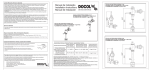
1
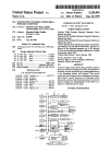
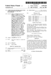
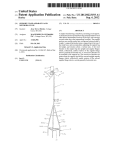
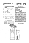
US006652170B1
(12)
(54)
United States Patent
(10) Patent N0.:
Arnold
(45) Date of Patent:
PORTABLE PRINTER AND DATA ENTRY
DEVICE ASSEMBLY
_
-
(75) Inventor. (GUrgigory B. Arnold, Centerville, OH
.
(73)
.
Asslgnee: F333“ Amencas’ Inc" Dayton’ OH
Notice:
Subject to any disclaimer, the term of this
Pawnt is extended or adjusted under 35
U.S.C. 154(b) by 364 days.
FOREIGN PATENT DOCUMENTS
0 191 495
8/1986
EP
0 199 252
10/1986
EP
0 250 910
JP
5-108522
EP
JP
(63)
_
1/1988
*
4/1993
11138911 A * 5/1999
2000025304 A
*
1/2000
............ .. B41J/3/36
.......... .. B41J/29/38
OTHER PUBLICATIONS
Symbol Technologies, Inc. manual entitled SPT 1500, pp. 1
Agiohm Thermal Printer Mechanism, User’s Manual THTP
Series, Preliminary Issue, reference 3104660—FDE, Oct.
Related US. Application Data
_
“A986
through 20, Copyright 1998.
Sep- 20, 2000
_
0 200 945
Symbol Technologies, Inc. internet site, Product Informa
1500 Palm Terminal Series, pp. 1 through 3, Mar.
(21) App1_ No; 09/665,813
(22) Filed:
Nov. 25, 2003
EP
JP
(*)
US 6,652,170 B1
_
1998_
_
Symbol Technologies, Inc., internet site, MSR 3000 Mag
contlnuatlon'ln'part of apphcatlon NO- 09/384575: ?led on
netic Stripe Reader For SPT 1700 and PPT 2700 Pocketable
Aug‘ 27’ 1999'
(51) Int. c1.7 ................................................. .. B41J 3/36
Computers, pp. 1 through 3, Feb. 3, 2000.
Symbol Technjologies, Inc» internet Site, PPT 2700 Series
(52) US.
Cl. ........................ .. 400/88; 400/693; 347/222_
-
59911511562355;
if-ciltggozlgh
if?)
3t, 2000
u]1 su
prm
ea , W0 pages.
(58)
Publication, Semek, Model 908x, 608x, 408x (Card
reader), one page.
Field of Search ........................ .. 400/88,
(56)
References Cited
Solvepoint DockVTM and DockV ProTM Instruction Guide,
copyright 1999—2000, tWo pages.
PalmV(X)TM adapter for PalmIII accessories, one page.
US. PATENT DOCUMENTS
DQ457200 s
*
4,727,245 A *
4,734,710 A
4,788,658 A
* cited by examiner
2/1988 Dobbins et a1.
Primary Examiner—Daniel J. Colilla
235/432 X
* 3/1988 Sato et a1. ............ .. 235/432 X
* 11/1988 Hanebuth ................. .. 361/684
5,047,615 A *
5,057,676 A
5,237,487 A
5,371,348 A
7/1977 Packard ..................... .. D18/11
9/1991 Fukumoto et a1.
* 10/1991
* 8/1993
* 12/1994
235/432
Komaki ............. ..
235/432
Dittmer et a1. ........... .. 361/729
Kumar et a1. ........ .. 235/472.02
5,468,947 A * 11/1995 Danielson et a1.
5,483,624 A
235/47202
1/1996 Christopher et a1. ...... .. 395/117
5,486,259 A
1/1996 Goodwin et a1.
156/384
5,488,558 A
*
1/1996
Ohki ........................ .. 701/207
5,808,283 A
*
9/1998 Stanton et a1. ........ .. 235/432 X
5,816,725 A * 10/1998 Sherman et a1.
........
235/47201 X
5,930,770
A
*
7/1999
Edgar
6,010,067
A
*
1/2000
Elbaum
6,195,589 B1 *
2/2001
Ketcham ................... .. 700/28
... ..
. . . ..
235/46243 X
. . . . . . . . . ..
(74) Attorney, Agent, or Firm—Joseph J. Grass
(57)
ABSTRACT
There is disclosed an assembly of a portable data entry
device and a portable printer. The printer is hand-held and
carries the data entry device. The data entry device includes
a scanner and is located at the front portion of the printer.
The printer has a space for accommodating a label roll and
a print module Which are located at the rear portion of the
printer. The printer can be used With different data entry
devices by use of adapters.
235/380
14 Claims, 5 Drawing Sheets
U.S. Patent
Nov. 25,2003
Sheet 1 0f 5
US 6,652,170 B1
U.S. Patent
Nov. 25,2003
Sheet 2 0f 5
US 6,652,170 B1
U.S. Patent
Nov. 25,2003
Sheet 3 0f 5
US 6,652,170 B1
U.S. Patent
Nov. 25,2003
Sheet 5 0f 5
US 6,652,170 B1
US 6,652,170 B1
1
2
PORTABLE PRINTER AND DATA ENTRY
DEVICE ASSEMBLY
betWeen the compartment and the printhead. An improved
elastomeric grip includes an actuator and a data port plug. A
CROSS-REFERENCE TO RELATED
APPLICATION
speci?c embodiment of the printer includes an elongate
hand-held housing having a front portion Which has a
compartment or pocket for receiving a data entry device.
This is a continuation-in-part of co-pending application
Ser. No. 09/384,675, ?led Aug. 27, 1999.
The housing also has a rear portion. There is space at the rear
portion for receiving a roll of a label Web. Aprint module or
mechanism is disposed at the rear portion for printing on the
label Web, and the print module including a thermal print
head and a platen roll cooperable With the print head. It is
preferred that the housing compartment have an open top for
BACKGROUND OF THE INVENTION
1. Field of the Invention
access to the data entry device. The platen roll is preferably
This invention relates to the ?elds of portable printers and
mounted on a cover for an access opening to the label roll
portable data entry devices.
2. Brief Description of the Prior Art
The following prior art is made of record: US. Pat. Nos.
15
5,486,259 and 5,483,624; Symbol Technologies, Inc.
space. A set of batteries and the print module are preferably
mounted on an elongate circuit board disposed in the printer
housing. The batteries are preferably located at the front
portion of the printer housing. The compartment is prefer
ably open-fronted and is channel-shaped for slidably, receiv
manual entitled SPT 1500, pages 1 through 20, Copyright
1998; Symbol Technologies, Inc. internet site, Product
ing the data entry device.
Information, SPT 1500 Palm Terminal Series, pages 1
through 3, Mar. 23, 1999; AXiohm Thermal Printer
Mechanism, User’s Manual THTP Series, Preliminary Issue,
reference 3104660-FDE, October, 1998.
SUMMARY OF THE INVENTION
BRIEF DESCRIPTION OF THE
DIAGRAMMATIC DRAWINGS
FIG. 1 is a perspective vieW of an assembly of a portable
25
The invention relates to a portable printer Which can be
ning a bar-coded label;
FIG. 2 is a partly eXploded perspective vieW of the
coupled to a portable data entity device, and When so
coupled the combination is a portable assembly Which in
general can be conveniently carried from place-to-place and
Which in particular is hand held.
The invention relates to an improved lightWeight,
portable printer and the portable data entry device separated
and With the cover open;
FIG. 3 is a generally vertical sectional vieW of the
assembly shoWn in FIG. 1;
portable, hand-held, user-friendly printer for reception of a
FIG. 4 is a perspective vieW of a printed circuit board of
the printer With batteries and a print module shoWn mounted
lightWeight, portable hand-held, user-friendly data entry
device, and to a combination of such a printer and such a
data entry device.
35
thereon;
FIG. 5 in an elevational vieW of one of the tWo mirror
It is a feature of the invention to provide an improved
image housing sections;
printer adapted to receive portable data entry devices having
different shapes. In particular, different models of portable
FIG. 6 is a fragmentary sectional vieW illustrating the
channel shape of the compartment for receiving the portable
data entry device;
data entry devices of the same or different manufacturers are
shaped differently. In order to have various portable data
entry device piggyback onto the printer Without redesigning
FIG. 7 is a fragmentary perspective vieW of the print
module and the cover and the platen roll mounted by the
the printer, an adapter or adjuster is provided to accommo
date differently shaped data entry devices.
According to a speci?c embodiment of the invention, a set
printer and portable data entry device, Which is hand-held
and portable, shoWing the portable data entry device scan
cover;
45
FIG. 8 is a partially eXploded perspective vieW of a
of adapters is provided to receive correspondingly shaped
portable data entry devices. Instead of redesigning the
portable printer including a compartment or adapter for
receiving a portable data entry device;
printer housing for each different data entry device, a
different adapter are provided and each adapter is shaped to
FIG. 9 is an eXploded perspective vieW of a different
adapter for use With a different data entry device;
FIG. 10 is a perspective vieW similar to FIG. 9 but
?t With a corresponding data entry device. Depending on the
shape of the data entry device to be used, the adapter
corresponding to that data entry device is assembled along
With the remainder of the housing When the printer is being
manufactured. Alternatively, in the event a printer has an
adapter for one data entry device, the printer can be readily
made to accommodate another and differently shaped data
entry device by matching a different adapter to that other
data entry device and substituting it on the printer housing.
55
8 removably coupled to the portable data entry device;
FIG. 13 is an eXploded perspective vieW of the printer
shoWn in FIGS. 8 and 12;
FIG. 14 is a perspective vieW shoWing the underside of
the adapter also shoWn in FIGS. 8 and 11, together With a
connector;
FIG. 15 is a generally vertical sectional vieW of the printer
and data entry device of the embodiment of FIGS. 8 and 11
It is another feature of the invention to provide an
improved portable printer having a loWer housing section,
an upper housing section, and a compartment connected to
the upper housing section for receiving a portable data entry
device in piggyback fashion. One or more printed circuit
boards are disposed betWeen the upper and loWer sections.
There is a battery compartment in the loWer housing section,
and a card reader and a printer module including a print head
are mounted on the circuit board. The card reader is disposed
shoWing yet another different adapter for use With yet
another different data entry device;
FIG. 11 is a bottom plan vieW, partly in section, of the
adapter shoWn in FIG. 8;
FIG. 12 is a perspective vieW of the printer shoWn in FIG.
65
through 14; and
FIG. 16 is a sectional vieW taken at line 16—16 of FIG.
13.
US 6,652,170 B1
4
3
DETAILED DESCRIPTION OF THE
PREFERRED EMBODIMENTS
With reference to FIG. 1, there is shown an assembly
removably received in a C-shaped cutout 54 in a ?ange 55.
The end of the cover 52 opposite the platen 45 has a pair of
generally indicated at 10 of a portable printer generally
recesses 57 in the housing sections 18 and 19. Accordingly,
indicated at 11 and a portable data entry device generally
indicated at 12. The printer 11 and the device 12,
individually, as Well as the assembly 10 are portable and in
the cover 52 is pivotally mounted for movement betWeen a
closed or operating position shoWn in FIGS. 1 and 3 and an
open or non-operating position as illustrated in FIG. 2. It is
apparent When the cover 52 is in the position shoWn in FIG.
2, a label roll R can be readily inserted into the space 35. If
outWardly extending projections 56 for receipt in opposed
particular are hand-held for ease of use. The device 12
includes a scanner 13 at its front end for scanning a
bar-coded label L. The device 12 also has manually operable
keys 14 and a display 15. The scanner 13, the keys 14 and
the display 15 are housed in an elongate relatively thin
10
housing 16. Manually depressing buttons 14‘ operates the
scanner 13.
The printer 11 is shoWn to have an elongate housing 17
having opposed mirror-image housing sections 18 and 19.
be readily replaced by snapping the portion of the shaft 46
15
The front portion of the housing 17 has a compartment or
As best shoWn in FIG. 4, the print module 34 and
data entry device 12. The compartment 20 has an open top
21 to enable the keys to be operated and to enable the display
15 to be seen. The compartment 20 is channel-shaped as
upstanding battery contacts 58 are mounted on a printed
circuit board 59. The connector 31 is connected to the
printed circuit board 59 via conductors 31‘. A ribbon con
diagrammatically depicted in FIG. 6 to capture the data entry
device 12. As shoWn, the housing 17 has ?anges 22 and 23
Which help retain the device 12 captive in the compartment
nector 60 connects the print head module 34, particularly the
motor 47, the print head 38 and sensors (not shoWn) to the
25
to the printed circuit board 59. A port 64 accessible from
outside the housing 17 is connected to the printed circuit
opposed projections 28 Which are received in recesses 29 in
board 59. The batteries 62 are held in a holder generally
the housing 16 of the device 12. By simultaneously depress
ing both pads 26 rearWardly of the Wall 27, the projections
indicated at 64 Which holds the batteries 62 in position but
keep the batteries 62 from touching each other. The holder
28 are WithdraWn from the recesses 29 Which alloWs the
64 maintains the batteries 62 aligned With opposed pairs of
35
housing 17. As the device 12 is slid into the compartment 20
the printed circuit board 59 by integrally molded pins 68.
The holder 64 is particularly bene?cial in the event the
assembly 10 or the printer 11 is dropped or otherWise
the rear end of the compartment 20, thereby enabling the
data entry device 12 to control the printer 11. The latches 25
impacted.
are latched When the connectors 30 and 31 are connected.
The printed circuit board 59 is captive betWeen the
As is apparent from FIG. 3, the underside of the printer
housing 17 has a holloW or concave surface 32 for receiving
45
a hand as shoWn in FIG. 3. FIG. 3 also shoWs the device 12
diagrammatically and that a label roll R and a prior art print
module or print mechanism generally indicated at 34 are
disposed at a rear portion of the printer 11. The label roll R
is illustrated as being comprised of a label Web (or a Web of
labels) W received in space 35 in the housing 17. The roll R
is suitably supported either at its central opening 36 or
simply in a cradle 37 as shoWn. The Web W passes from the
roll R betWeen a thermal print head 38 and a platen roll 39.
The printed label Web W eXits the housing 17 at a slot 40 one
side of Which is formed by a tear edge 41.
FIG. 7 shoWs that the print module 34 comprises a frame
42 Which has sockets 43 and 44. The module 34 includes a
platen roll 39 having a shaft 46. The shaft 46 is releasably
held in the sockets 43 and 44 in the FIG. 3 position. The
module 34 further includes an electric motor 47 and gearing
generally indicated at 48. The gearing 48 includes gear 49 on
the shaft 46. Springs 50 Which bear against a support 51
resiliently mount the print head 38.
The platen roll 45 is rotatably mounted to a cover 52. In
particular, the shaft 46 passes through a ?ange 53 and is
contacts 58. The holder 64 surrounds the outsides of all the
batteries 62 as best shoWn in FIG. 4. The holder 64 has
?n-like separators 65 joined to a peripheral Wall 66 and to a
bottom Wall 67 (FIG. 3) The bottom Wall 67 is connected to
in the direction of arroW A in FIG. 2, the connector 30 at the
rear end of the device 12 connects With the connector 31 at
the palm of the user’s hand. Astrap 33 can ?t about the back
of the user’s hand. The strap 33 can be a continuous loop of
printed circuit board via a connector 61. There are four
contacts 58 on each side of the printed circuit board 59 for
releasable contact to four rechargeable batteries 62. The
connector 31 Which is mounted to a support 63 is connected
20. The device 12 is releasably latched in the compartment
20 by opposed latches 25. The latches 25 are each comprised
of a pad 26 ?exibly secured to a Wall 27. The pads 26 have
device 12 to be slid out of the compartment 20.
The underside of the device 12 has a 10-pin connector 30
Which cooperates With a mating 10-pin connector 31 on the
betWeen the ?anges 55 and the gear 49 out of the socket 44,
and pulling the other end of the shaft 46 out of the hole in
the ?ange 53.
space or pocket 20 for receiving and releasably holding the
20. The front end of the compartment 20 is open as indicated
at 24 to enable the device 12 to be slid into the compartment
the roll R has a core C as shoWn the core can be readily
removed. Also, the print head 38 and the platen roll 39 can
be readily cleaned When the cover is in the open position. If
required, the platen roll 45, its shaft 46 and its gear 49 can
housing sections 18 and 19 in transverse slots 69 and 70. The
support 63 is received in slots 71 and 72. The housing
sections 18 and 19 are connected by screWs (not shoWn)
received in aligned holes 74.
Floor 75 of the compartment 20 is provided With an access
opening 76 Which is closed off by a cover 77. The door 77
is pivotally mounted about a hinge aXis 78 for movement
betWeen the closed position shoWn in FIG. 2 and an open
position to provide access for loading and removing the
55
batteries 24. The cover 77 is releasably held in the closed
position by a releasable latch 78‘.
The printer 11 is compact, by Way of eXample not
limitation, one embodiment of the printer 11 has a length of
about 8.31 inches (211 mm), a height 2.38 inches (60 mm),
a Width of 3.38 inches (86 mm) and a Weight of 0.9 pound
(0.4 kg.); and the data entry device 12 has a length of 5.46
inches (140 mm), a height of 0.66 inch (17 mm), a Width of
3.16 inches (81 mm), and a Weight of 6.1 ounces (0.17 kg).
With reference to FIG. 8, there is shoWn the portable data
entry device 12 and a printer 80. The printer 80 has an
65
elongate housing 81 having a loWer housing section 82 and
an upper housing portion 83. An adapter or adjuster 84 is
connected to the upper housing section 83 by a plurality of
threaded fasteners 85. The adapter 84 together With upper
US 6,652,170 B1
5
6
surface 86 of the housing section 82 forms a compartment 87
portion of the housing 81 and a magnetic card reader
generally 102 is disposed betWeen the data entry device
receiving compartment 87 and the print head module 101
With its print head 101‘. So, therefore, data can be printed by
the printer 80 from data received from the data entry device
for receiving the data entry device 12 in piggyback fashion
as shoWn in FIGS. 12 and 15.
FIGS. 8, 9 and 10 shoW a set of three different adapters 84,
84‘ and 84“ and a set of three corresponding different data
entry devices 12, 12‘ and 12“. Thus, the adapter 84 is shaped
12, from the card reader 102 or through data ports 103 or 104
to ?t or accommodate the data entry device 12, the adapter
84‘ is shaped to ?t or accommodate the data entry device 12‘,
and the adapter 84“ is shaped to ?t or accommodate the data
entry device 12“. As shoWn the data entry device 12‘ is
narroWer than the data entry device 12 and the data entry
device 12“ is thicker than the data entry devices 12 and 12‘.
It is thus apparent that the printer 81 can be readily modi?ed
or adjusted to accommodate different data entry devices.
The adapters 84, 84‘ and 84“ are all shoWn to have a
(FIG. 13).
The data ports 103 and 104 are mounted on a U-shaped
10
ductor 107 is shoWn to connect the connector 94 to the
printed circuit board 106. The print head module 101 and the
card reader 102 are mounted on and are electrically con
15
side margins of the printed circuit board 106. The lands 108
are joined to a pair of parallel, vertical, opposed Walls 109.
The printed circuit board 105 is secured to a rigid post 110
by a screW 111 betWeen the Walls 109. The lands 108 have
25
Alternatively, or in addition, it is preferred that the adapter
84 be comprised of an elastomeric material Which Will
enable the data entry device to be yieldably held in the
docked position in the compartment 87. Thus, the data entry
device 12 is frictionally held in the compartment 87 by the
gripper members 91 and 93‘. The Wall sections 88 and 90 are
integrally joined to a horiZontally extending U-shaped
retaining ?ange 92. The compartment 87 is provided by the
Wall sections 88 and 90, the ?ange 92 and the upper surface
86 of the upper housing section 83. End edge portion 93 is
sculptured or tailored to the data entry device 12 so that keys
14 can be operated While the data entry device 84 is docked
in the compartment 87. The top portion of the adapter 84 is
open, in the same Way as the compartment 20 is open to
enable the display 15 to be seen.
The data entry device 12‘ is narroWer than the data entry
device 12 and thus the distance betWeen Walls 88‘ is less than
the distance betWeen the Walls 88 so as to ?t or accommo
date the data entry device 12‘ betWeen Wall sections 88‘.
The data entry device 12“ has a different arrangement of
buttons 14“ than the data entry devices 12 and 12‘ and as
such the horiZontal ?ange 9“ is sculptured or tailored to
(FIG. 15). When the print head module 101 prints, the
portion 113.
As best shoWn in FIG. 13, a pair of manually engageable
members 123 and 124 are secured to the outside surfaces of
45 Walls 109. The members 123 and 124 are identical except
that the member 123 has a differently shaped rectangular
plug 125 from rectangular plug 126 of the member 124. The
plug 125 ?ts into a hole 127 and the plug 126 ?ts into a hole
127. The members 123 and 124 are each of one-piece
molded, resilient, elastomeric construction. Each member
123 and 124 has inner surfaces With three identical undercut
projections 128. The projections 128 ?t through holes 129 in
the Walls 109 and are captured at the undercut 130 as best
shoWn in FIG. 16. The inside surfaces of the members 123
55 and 124 from Which the projections 128 extend also have a
raised or convex portion 131. Each convex portion 131 is
aligned With a sWitch 132. If either sWitch 132 is depressed
the scanner 13 Will be operated to read the bar code on the
label L. Convex portions 133 on the outside surfaces of each
of the members 123 and 124 are aligned With the convex
portions 131 and are depressible by the user to operate the
sWitches 132. The plugs 125 and 126 are preferably posi
tioned in respective openings 127 and 127‘ When the ports
entry device 12 are used in the same manner as in the
embodiment of FIGS. 1 through 7. The data entry device 12
is disposed at a front portion of the printer housing 81. A
printer module 101 and space S de?ned by a surface 81‘ for
mounting a label supply roll R are disposed at the rear
holes 112 through Which screWs 85 pass into the adapter 84.
In this Way the adapter 84 is held securely to the loWer
housing section 82 and to the upper housing section 83.
The upper housing section has an inclined portion 113
With a door 114 pivotally mounted on spaced arms 113‘ by
tWo studs 115 received in opposed holes 116. The door 114
rotatably mounts a platen roller 117 Which cooperates With
the print head 101‘ as shoWn in FIG. 15. The door 114 has
a ?exible handle 118 for assisting the user in opening the
door 114.
The card reader 101 is used to read a magnetic card MC.
The adapter 84 and the adjacent Wall 113“ of the inclined
portion 113 are spaced to provide a slot S‘ so that the
magnetic card MC can pass therethrough betWeen members
119 and 120. The card reader 102 has a pair of U-shaped
members 119 and 120. The member 119 is positioned at
opening 121 in the adapter 84. The other member 120 is
positioned at an opening 121‘ of the inclined portion 113
printed labels L issue through an opening 122 in the inclined
alloW access to the buttons 14“.
In other respects the adapters 84‘ and 84“ are identical to
the adapter 84. As seen in FIGS. 8, 13 and 14, a coupling C
in the form of a connector generally 94 is secured by screWs
95 to the top or ?ange 92. The Wall section 90 has a stepped
opening 96 (FIG. 14). The connector 94 has a vertical collar
97 and a horiZontal bar 98. The Wall 90 is positioned
betWeen the collar 97 and the bar 98 to help hold the
connector 94 in position on the adapter 84. The connector 94
is also positioned against an upstanding projection 99 on the
upper housing section 83. The front upper portion of the
connector 94 has a plurality of contacts 100 for contacting
mating contacts on the data entry device 12.
As seen in FIG. 12 for example, the printer 80 and the data
nected to the printed circuit board 106.
As shoWn in FIG. 13, the housing section 81 has a pair of
longitudinally extending horiZontal lands 108 Which support
generally U-shaped con?guration and are each preferably of
one-piece molded construction. The adapter 84 has verti
cally extending Wall sections 88 and 89 and a Wall section
90. The Wall sections 89 and 90 are parallel and the Wall
sections 88 are generally parallel to each other. Opposed
faces of the Wall sections 88 have frictional or gripper
members 91 Which grip the housing 16 of the data entry
device 12. The housing 16 of the device 12 also has a lip or
gripper 16‘ Which cooperates With a ridge 93‘ on the adapter
84 to help releasably hold the device 12 to the printer 80.
printed circuit board 105. The printed circuit board 105 is
electrically connected to a printed circuit board 106. Con
103 and 104 are not in use. HoWever, by ?exing the
65
members 123 and/or 124 to their phantom line positions
shoWn at PL in FIG. 13, the respective ports 103 and 104 can
be uncovered for use.
US 6,652,170 B1
7
8
The lower housing section has a compartment 134 for
receiving a battery 135 connected to the printed circuit board
for powering the printer and its electronics. A door 136
closes the compartment 134.
3. In the combination de?ned in claim 2, including a
compartment on the housing for a battery to poWer the print
head.
By Way of example, not limitation, the print head module
in the housing, a set of at least tWo different shaped adapters,
4. Aportable printer, comprising: a housing, a print head
the housing including one of the adapters, and each adapter
being shaped to receive a correspondingly shaped portable
101 can be a Fujitsu FTP 638MCL100 print head module
and the card reader 102 can be a Semek 4083-0 card reader.
Other embodiments and modi?cations of the invention
Will suggest themselves to those skilled in the art, and all
such of these as come Within the spirit of this invention are
included Within its scope as best de?ned by the appended
claims.
What is claimed is:
1. In combination: a portable printer, at least tWo differ
ently shaped portable entry devices, each portable entry
data entry device.
5. A portable printer as de?ned in claim 4, Wherein each
adapter is generally U-shaped.
6. A portable printer as de?ned in claim 4, and a fastener
for connecting one of the adapters to the remainder of the
housing.
7. A portable printer as de?ned in claim 4, Wherein each
adapter has an open top portion to alloW operation of the
15
entry device housing for the scanner, the portable printer
including a printer housing having a front portion, a set of
at least tWo different adapters each shaped to receive one of
the data entry devices, one of the adapters being disposed at
battery for poWering the print head.
10. A portable printers de?ned in claim 4, Wherein each
the front portion, the printer housing having a rear portion,
the printer housing providing space at the rear portion for
receiving a roll of a label Web, a print head disposed at the
rear portion of the printer housing, and a data coupling
betWeen the received data entry device and the printer.
2. In combination: a portable printer, at least tWo differ
ently shaped portable data entry devices, the printer includ
ing a printer housing, a print head disposed in the housing,
at least tWo different adapters each shaped to receive one of
the data entry devices, the printer housing including one of
the adapters, and a data coupling betWeen the received data
entry device and the printer.
portable data entry device.
8. A portable printer as de?ned in claim 4, Wherein each
adapter has an open front portion.
9. A portable printer as de?ned in claim 4, including a
device including a scanner for scanning bar codes and a data
25
adapter has an open front portion and an open top portion.
11. A portable printer as de?ned in claim 4, including a
data connector secured to the adapter on the housing.
12. A portable printer as de?ned in claim 4, including a
frictional member for releasably holding a data entry in the
adapter on the housing.
13. Aportable printer as de?ned in claim 4, Wherein each
adapter includes a ?ange for helping to removably retain a
data entry device on the housing.
14. Aportable printer as de?ned in claim 4, Wherein each
?ange is generally U-shaped.
*
*
*
*
*