1
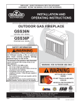
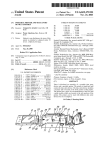
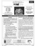
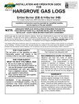
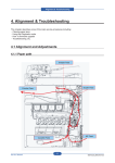
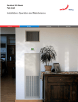
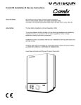
Service
Manual
PRODUCED & DISTRIBUTED BY:
24 Napoleon Road
Barrie, Ontario
Canada L4M 4Y8
Tel: 705-721-1212 Fax: 705-722-6031
TECHNICAL HELP LINE
Tel:
Fax:
Email:
Web:
1 - 888 - 721- TECH (8324)
1 - 877 - FAX - TECH (329-8324)
[email protected]
www.napoleonfireplaces.com
2005 WOLF STEEL LTD.
COPYRIGHT 2005 WOLF COPYRIGHT
STEEL LTD.
ALL RIGHTS RESERVED, NO PART OF THIS BOOK
MAY BE REPRODUCED
IN ANY
FORM
OR BY
MEANS - GRAPHIC,
OR MECHANICAL
WITHOUT
WRITTEN - GRAPHIC,
ALL RIGHTS
RESERVED,OR
NOTRANSMITTED
PART OF THIS
BOOK
MAY
BEANY
REPRODUCED
OR ELECTRONIC
TRANSMITTED
IN ANY FORM
ORTHE
BY PRIOR
ANY MEANS
PERMISSION FROM WOLF STEEL LTD., BARRIE, ONTARIO, CANADA
ELECTRONIC OR MECHANICAL WITHOUT THE PRIOR WRITTEN PERMISSION FROM WOLF STEEL LTD., BARRIE, ONTARIO, CANADA
ISO-176
ISO-176
ISO-176
W415-0118/A/07.05.05
W415-0118/A/.07.05.05
Wolf Steel’s Service Manual Index
Part 1: Troubleshooting: Direct Vents
Pilot Not Lighting Flowchart .................................................................................................... 1
Pilot Not Holding Flowchart ..................................................................................................... 2
Pilot Failure Flowchart .............................................................................................................. 3
Main Burner Not Lighting Flowchart ....................................................................................... 4
Main Burner Delayed Ignition Flowchart ................................................................................ 5
Main Burner Low Flame Flowchart .......................................................................................... 6
Main Burner Failure Flowchart ................................................................................................. 7
Complete Unit Shutdown...........................................................................................................8
Odour Flowchart ........................................................................................................................ 9
Part 2: Troubleshooting: Natural Vents
Pilot Not Lighting Flowchart .................................................................................................. 10
Pilot Not Holding Flowchart ................................................................................................... 11
Pilot Failure Flowchart ............................................................................................................ 12
Main Burner Not Lighting Flowchart ..................................................................................... 13
Main Burner Delayed Ignition Flowchart .............................................................................. 14
Main Burner Low Flame Flowchart ........................................................................................ 15
Main Burner Failure Flowchart ............................................................................................... 16
Complete Unit Shutdown ....................................................................................................... 17
Odour Flowchart ...................................................................................................................... 18
Part 3: Troubleshooting: Vent Free
Pilot Not Lighting Flowchart .................................................................................................. 19
Pilot Not Holding Flowchart ................................................................................................... 20
Pilot Failure Flowchart ............................................................................................................ 21
Main Burner Not Lighting Flowchart ..................................................................................... 22
Main Burner Delayed Ignition Flowchart .............................................................................. 23
Main Burner Low Flame Flowchart ........................................................................................ 24
Complete Unit Shutdown........................................................................................................ 25
Odour Flowchart ...................................................................................................................... 26
Part 4: Troubleshooting: Other Issues
Carboning Flowchart ............................................................................................................... 27
Oil-Canning Flowchart .............................................................................................................. 28
Blower Flowchart ..................................................................................................................... 29
Remote Control Guide ............................................................................................................ 30
Part 5: Testing & Adjustments
Testing: Pressures .................................................................................................................... 31
Testing: Gasket ......................................................................................................................... 32
Testing: Switches - Spill Switch .............................................................................................. 32
Testing: Switches - T.stat/Toggle ............................................................................................ 32
Testing: Millivolts - Thermocouple - Robertshaw Valve ...................................................... 33
Testing: Millivolts - Thermocouple - SIT 820 Nova Valve ...................................................... 34
Testing: Millivolts - Thermopile .............................................................................................. 35
Testing: Function - Magnet Coil - Robertshaw Valve .......................................................... 36
Testing: Function - Operator Coil - Robertshaw Valve ....................................................... 37
Testing: Function - Magnet Coil - SIT 820 Nova Valve ........................................................... 38
Testing: Function - Operator Coil - SIT 820 Nova Valve ........................................................ 39
Testing: Pilot Flame ................................................................................................................. 40
Adjustments: Pilot Flame ........................................................................................................ 41
Adjustments: Spill Switch - Robertshaw Valve..................................................................... 42
Adjustments: Spill Switch - SIT 820 Nova Valve ..................................................................... 43
Adjustments: Venturi/Air Shutter .......................................................................................... 44
COPYRIGHT 2005 WOLF STEEL LTD.
ALL RIGHTS RESERVED, NO PART OF THIS BOOK MAY BE REPRODUCED OR TRANSMITTED IN ANY FORM OR BY ANY MEANS - GRAPHIC, ELECTRONIC OR MECHANICAL WITHOUT THE PRIOR WRITTEN
PERMISSION FROM WOLF STEEL LTD., BARRIE, ONTARIO, CANADA
ISO-176
W415-0118/A/07.05.05
PART 1: TROUBLESHOOTING: DIRECT VENTS
Pilot Not Lighting Flowchart ................................................................................ 1
Pilot Not Holding Flowchart ................................................................................ 2
Pilot Failure Flowchart ......................................................................................... 3
Main Burner Not Lighting Flowchart .................................................................. 4
Main Burner Delayed Ignition Flowchart ............................................................ 5
Main Burner Low Flame Flowchart ...................................................................... 6
Main Burner Failure Flowchart ............................................................................ 7
Complete Unit Shutdown...................................................................................... 8
Odour Flowchart...................................................................................................... 9
COPYRIGHT 2005 WOLF STEEL LTD.
ALL RIGHTS RESERVED, NO PART OF THIS BOOK MAY BE REPRODUCED OR TRANSMITTED IN ANY FORM OR BY ANY MEANS - GRAPHIC, ELECTRONIC OR MECHANICAL WITHOUT THE PRIOR WRITTEN
PERMISSION FROM WOLF STEEL LTD., BARRIE, ONTARIO, CANADA
ISO-176
W415-0118/A/07.05.05
Page 1
Troubleshooting: Direct Vents
Pilot Not Lighting Flowchart
Has the inline
gas pressure
been tested?
NO
Remove the tube and orifice and
clean, make sure no debris has
compacted the inside, inhibiting
the flow of gas.
NO
Has the pilot
adjustment
screw been
checked?
YES
Ensure the adjustment screw has
not been tightened closed. Adjust
as necessary. (See "Adjustments:
Pilot Flame")
NO
NO
Secure /
Replace as
necessary.
Is there a 1/8"
gap between
the electrode
and the pilot
hood?
NO
Adjust position
so there is no
greater than a
1/8" gap.
Has the
electrode been
examined for
damage? (i.e.
chipped/broken)
NO
Replace if
damaged or
broken.
YES
Have the pilot
light & pilot
orifice been
checked for
blockages?
Is the electrode
wire connection
secure?
YES
NO
YES
Check to ensure proper supply
pressures are available for ignition.
(See "Testing: Procedures")
YES
YES
Is there a spark at the electrode when the push button igniter is pressed?
NO
Are the fittings
on the pilot
tube secure?
YES
Tighten / secure to prevent leaks.
NO
Has the pilot
tube been
checked for
kinks / leaks?
YES
Un-kink the tube to prevent
blockage, or replace leaking tube.
Ensure the opening is not blocked
or plugged. Clear if necessary.
NO
Has the primary
air opening on
the pilot
assembly been
checked for
blockages?
COPYRIGHT 2005 WOLF STEEL LTD.
ALL RIGHTS RESERVED, NO PART OF THIS BOOK MAY BE REPRODUCED OR TRANSMITTED IN ANY FORM OR BY ANY MEANS - GRAPHIC, ELECTRONIC OR MECHANICAL WITHOUT THE PRIOR WRITTEN
PERMISSION FROM WOLF STEEL LTD., BARRIE, ONTARIO, CANADA
ISO-176
W415-0118/A/07.05.05
Page 2
Troubleshooting: Direct Vents
Pilot Not Holding Flowchart
NO
Tighten thermocouple to ensure proper millivolt
delivery.
NO
Clean any buildup off of the tip of the
thermocouple to maximize it's exposure to the
flame.
NO
Test the thermocouple to ensure it is within
specifications. (See "Testing: Millivolts Thermocouple")
YES
Has the thermocouple connection been checked?
YES
Is the tip of the thermocouple clean?
YES
Has the thermocouple been tested for millivolt
generation?
NO
Test the magnet coil to ensure it is within
specification. (See "Testing: Function - Magnet
Coil")
YES
Has the magnet coil of the valve been checked for
function?
Is the supply line size adequate for the
installation?
NO
Check the local code requirements and replace as
necessary.
COPYRIGHT 2005 WOLF STEEL LTD.
ALL RIGHTS RESERVED, NO PART OF THIS BOOK MAY BE REPRODUCED OR TRANSMITTED IN ANY FORM OR BY ANY MEANS - GRAPHIC, ELECTRONIC OR MECHANICAL WITHOUT THE PRIOR WRITTEN
PERMISSION FROM WOLF STEEL LTD., BARRIE, ONTARIO, CANADA
ISO-176
W415-0118/A/07.05.05
Page 3
Troubleshooting: Direct Vents
Pilot Failure Flowchart
NO
Check to make sure the pilot is large enough and in
the proper position, to properly heat the
thermocouple. (See "Testing: Pilot Flame")
YES
Check to make sure the pressure is not dropping
off on activation. (See "Testing: Pressures")
NO
Test the thermocouple to ensure it is within
specifications. (See "Testing: Millivolts Thermocouple")
YES
Is the pilot flame pattern, position and size
correct?
NO
Is the pilot flame shrinking when the burner is
turned on?
YES
Has the thermocouple been tested for millivolt
generation?
NO
Test the magnet coil to ensure it is within
specification. (See "Testing: Function - Magnet
Coil")
YES
Has the function of the magnet coil been
checked?
NO
(See "Complete Unit Shutdown" Flowchart)
YES
Has the vent system been examined for problems?
Are the logs properly positioned?
NO
Out of place logs can alter the flow of air within
the combustion chamber, causing an erratic pilot.
COPYRIGHT 2005 WOLF STEEL LTD.
ALL RIGHTS RESERVED, NO PART OF THIS BOOK MAY BE REPRODUCED OR TRANSMITTED IN ANY FORM OR BY ANY MEANS - GRAPHIC, ELECTRONIC OR MECHANICAL WITHOUT THE PRIOR WRITTEN
PERMISSION FROM WOLF STEEL LTD., BARRIE, ONTARIO, CANADA
ISO-176
W415-0118/A/07.05.05
Page 4
Troubleshooting: Direct Vents
Main Burner Not Lighting Flowchart
NO
Connect the thermopile leads to the 1st & 2nd
terminals on the valve (THTP & TP).
NO
Test the thermopile to ensure it is within
specifications. (See "Testing: Millivolts Thermopile").
NO
Check and clean as required.
YES
Have the thermopile leads been connected to the
1st & 2nd terminals on the valve (THTP & TP)?
YES
Has the thermopile been tested for millivolt
generation?
YES
Has the burner & orifice been checked for
blockages?
NO
Connect a
switch or
remote to
terminals 1 & 3.
YES
Is there a switch or remote connected on
terminals 1 & 3?
NO
Test the operator coil of
the valve for resistance.
Replace the valve if out
of specification. (See
"Testing: Function Operator Coil")
NO
YES
Disconnect switch or remote at valve and replace
with a jumper wire. Did the burner activate?
See "Testing: Switches - T.Stat/Toggle"
COPYRIGHT 2005 WOLF STEEL LTD.
ALL RIGHTS RESERVED, NO PART OF THIS BOOK MAY BE REPRODUCED OR TRANSMITTED IN ANY FORM OR BY ANY MEANS - GRAPHIC, ELECTRONIC OR MECHANICAL WITHOUT THE PRIOR WRITTEN
PERMISSION FROM WOLF STEEL LTD., BARRIE, ONTARIO, CANADA
ISO-176
W415-0118/A/07.05.05
Page 5
Troubleshooting: Direct Vents
Main Burner Delayed Ignition Flowchart
NO
Check to make sure the pilot is large
enough and in the proper position,
to reach the ignition ports. (See
"Testing: Pilot Flame")
NO
Check to ensure the proper supply
pressures are available for ignition.
(See "Testing: Pressures")
NO
Check to make sure nothing is
blocking the flow of gas through the
burner and orifice, contributing to
the delay. Clean as necessary.
NO
Check the size of the orifice and
ensure it meets manufacturers
specification.
NO
Check the venturi setting and adjust
as necessary to improve the ignition
time. (See "Adjusting: Venturi")
NO
Check to ensure the door is tightly
sealed and not allowing any air into
the air-shutter chamber, and that the
gasket is intact.
YES
Has the pilot flame position and size been examined?
YES
Has the inline gas pressure been tested?
YES
Has the main burner & orifice been checked for blockages?
YES
Has the main burner orifice been examined to see if it is the
right size?
YES
Has the venturi (air shutter) been checked & adjusted?
YES
Has the venturi access door been checked?
NO
Examine and level as necessary.
YES
Has the burner been checked to ensure it is level?
NO
Out of place logs can alter the flow
of air within the combustion
chamber, causing an erratic pilot.
NO
Check to make sure no ember
material is clogging the ports, and
contributing to the delay.
NO
Ensure the venting is sealed and
there are no leaks.
YES
Has the positioning of the logs been checked?
YES
Have the charcoal / glowing embers (where applicable) been
checked?
YES
Has the venting been examined?
Has the main door seal been checked?
NO
Check to make sure no air is leaking
in around the seal, which can affect
the flow of air in the combustion
chamber.
COPYRIGHT 2005 WOLF STEEL LTD.
ALL RIGHTS RESERVED, NO PART OF THIS BOOK MAY BE REPRODUCED OR TRANSMITTED IN ANY FORM OR BY ANY MEANS - GRAPHIC, ELECTRONIC OR MECHANICAL WITHOUT THE PRIOR WRITTEN
PERMISSION FROM WOLF STEEL LTD., BARRIE, ONTARIO, CANADA
ISO-176
W415-0118/A/07.05.05
Page 6
Troubleshooting: Direct Vents
Main Burner Low Flame Flowchart
YES
Check to see if the remote has power. When
power is unavailable, the remote defaults to a
low-flame mode until it's restored.
NO
Turn the knob to its higher setting.
NO
Check to ensure the proper supply and flow
condition pressures for optimal burn. (See
"Testing: Pressures")
NO
Does the fireplace have a modulating remote?
YES
Is the hi-lo knob set to a high setting?
YES
Have the inlet + outlet gas pressures have been
tested?
NO
Check the size of the orifice and ensure it meets
manufacturers specification.
NO
Check to make sure nothing is blocking the flow of
gas through the burner and orifice, which could
result in low flame. Clean as necessary.
NO
Check the venturi setting and adjust as necessary
to improve the flame appearance. (See
"Adjustments: Venturi")
NO
Remove the tube to make sure no debris has
compacted inside, inhibiting the flow of gas. Clean
as necessary.
YES
Has the main burner orifice been examined to see
if it is the right size?
YES
Has the main burner and orifice been checked for
blockages?
YES
Has the venturi (air shutter) been checked +
adjusted?
Has the manifold tube been checked for
blockages?
COPYRIGHT 2005 WOLF STEEL LTD.
ALL RIGHTS RESERVED, NO PART OF THIS BOOK MAY BE REPRODUCED OR TRANSMITTED IN ANY FORM OR BY ANY MEANS - GRAPHIC, ELECTRONIC OR MECHANICAL WITHOUT THE PRIOR WRITTEN
PERMISSION FROM WOLF STEEL LTD., BARRIE, ONTARIO, CANADA
ISO-176
W415-0118/A/07.05.05
Page 7
Troubleshooting: Direct Vents
Main Burner Failure Flowchart
Has the pilot
flame position
and size been
examined?
Is the burner flame going
ghostly and blue before
extinguishing?
NO
Are the electrical
connections
(thermopile, switch,
remote, thermostat),
clean/secure/unbroken?
(See "Complete Unit
Shutdown"
Flowchart)
YES
Clean, tighten, or replace as
necessary.
YES
NO
YES
Check to make sure the pilot flame is
adequately covering the thermopile
+ thermocouple. (See "Testing: Pilot
Flame)
NO
YES
Is the burner flame spontaneously going out without any change in flame
appearance?
NO Has the wiring for the
thermostat/switch (if
applicable) been
checked for proper
length/size?
YES
Check to ensure that the length
and gauge of the wire have not
exceeded their listed
maximums, and that the wire is
not coiled at any point.
NO
Has the
thermopile
been tested for
millivolt
generation?
Test the operator coil to ensure it is
within specification. (See "Testing:
Function - Operator Coil")
NO
Has the
operator coil of
the valve been
checked for
resistance?
Does the main burner flame shrink
shortly after activation?
NO
Is the main
burner flame
staying the
same size when
turned on?
YES
YES
NO
Is it a
millivolt
switch?
Does the
unit have a
thermostat
connected
to it?
NO
Is it a
millivolt wall
thermostat?
NO
Remove and
replace with a
millivolt switch.
NO
Remove and
replace with a
millivolt wall
thermostat.
Does the unit have a
remote connected to
it?
YES
Does the
unit have a
switch
connected
to it?
Is it a Wolf Steel
approved remote?
(Advantage/Skytech)
NO
Check to make sure the pressure is
not dropping off on activation.
(See "Testing: Pressures")
YES
YES
YES
YES
Test the thermopile to ensure it is
within specifications. (See "Testing:
Millivolts - Thermopile")
Remove and replace
with a Wolf Steel
approved remote.
COPYRIGHT 2005 WOLF STEEL LTD.
ALL RIGHTS RESERVED, NO PART OF THIS BOOK MAY BE REPRODUCED OR TRANSMITTED IN ANY FORM OR BY ANY MEANS - GRAPHIC, ELECTRONIC OR MECHANICAL WITHOUT THE PRIOR WRITTEN
PERMISSION FROM WOLF STEEL LTD., BARRIE, ONTARIO, CANADA
ISO-176
W415-0118/A/07.05.05
Page 8
Troubleshooting: Direct Vents
Complete Unit Shutdown
NO
(See: "Pilot Failure" Flowchart)
NO
Check and seal/replace as necessary. (See "Testing:
Gasket")
NO
Add the 2nd collar to the terminal as per the
diagrams in the manual.
NO
Ensure that nothing is obstructing the flow of air &
exhaust from the terminal. Clear as necessary.
NO
Check the venting requirements and return to
specification.
YES
Is the burner flame going blue and see-through
before extinguishing?
YES
Have the seals on the venting, main door, relief
doors, around the burner and the pilot assembly
been checked for leaks?
YES
If the termination is vertical - has the 2nd storm
collar been used on the terminal?
YES
Has the termination been checked for blockages
and obstructions?
YES
Is the venting within the specifications of the
installation manual and local code requirements?
NO
Seal all inner and outer vent pipe connections.
YES
Has the venting been sealed on the inner and
outer vent pipe connections?
Does the venting meet the fireplace parameters
regarding length and rise?
NO
Ensure that the venting is within specified
parameters.
COPYRIGHT 2005 WOLF STEEL LTD.
ALL RIGHTS RESERVED, NO PART OF THIS BOOK MAY BE REPRODUCED OR TRANSMITTED IN ANY FORM OR BY ANY MEANS - GRAPHIC, ELECTRONIC OR MECHANICAL WITHOUT THE PRIOR WRITTEN
PERMISSION FROM WOLF STEEL LTD., BARRIE, ONTARIO, CANADA
ISO-176
W415-0118/A/07.05.05
Page 9
Troubleshooting: Direct Vents
Odour Flowchart
NO
YES
Has the unit had its required 'Burn-in' period?
Run the unit on its highest setting for 8-10 hours
with the blower shut off. (Note: Some lower BTU
units may require more than 1 burn-in period.)
Remember to ventilate the area.
NO
Check for leaks and seal as necessary. (See
"Testing: Gasket")
NO
Check to see if the unit is dusty and is burning off
accumulated dust from prolonged inactivity.
NO
Ensure that combustible materials are kept at least
four feet away from the front of the fireplace.
NO
Check the mantle clearances listed in the manual
against the specifics of the installation. Adjust or
remove the mantle as necessary.
NO
Check for the presence of vapor barrier, insulation,
or other material / construction-debris in contact
with the outer shell of the firebox.
NO
Reference installation manual and restore to
manufacturers specifications as necessary.
NO
Check the existing chimney for the presence of
creosote, which can, when heated, produce an
odour.
YES
Has the unit been checked for leaks around the
door seal, relief-door seals, vent collar (if possible),
and firebox?
YES
Is the unit being used frequently?
YES
Is the front of the fireplace clear of the presence
of any combustible materials?
YES
If the unit has a mantle - have the mantle
clearances been referenced for accuracy?
YES
Has the unit been installed in a finished wall?
YES
Have the required clearances to combustibles
been maintained?
Is the unit an insert?
COPYRIGHT 2005 WOLF STEEL LTD.
ALL RIGHTS RESERVED, NO PART OF THIS BOOK MAY BE REPRODUCED OR TRANSMITTED IN ANY FORM OR BY ANY MEANS - GRAPHIC, ELECTRONIC OR MECHANICAL WITHOUT THE PRIOR WRITTEN
PERMISSION FROM WOLF STEEL LTD., BARRIE, ONTARIO, CANADA
ISO-176
W415-0118/A/07.05.05
PART 2: TROUBLESHOOTING: NATURAL VENTS
Pilot Not Lighting Flowchart ......................................................................................... 10
Pilot Not Holding Flowchart ....................................................................................... 11
Pilot Failure Flowchart ................................................................................................ 12
Main Burner Not Lighting Flowchart ......................................................................... 13
Main Burner Delayed Ignition Flowchart .................................................................. 14
Main Burner Low Flame Flowchart ............................................................................ 15
Main Burner Failure Flowchart .................................................................................. 16
Complete Unit Shutdown ............................................................................................... 17
Odour Flowchart............................................................................................................. 18
COPYRIGHT 2005 WOLF STEEL LTD.
ALL RIGHTS RESERVED, NO PART OF THIS BOOK MAY BE REPRODUCED OR TRANSMITTED IN ANY FORM OR BY ANY MEANS - GRAPHIC, ELECTRONIC OR MECHANICAL WITHOUT THE PRIOR WRITTEN
PERMISSION FROM WOLF STEEL LTD., BARRIE, ONTARIO, CANADA
ISO-176
W415-0118/A/07.05.05
Page 10
Troubleshooting: Natural Vents
Pilot Not Lighting Flowchart
Has the inline
gas pressure
been tested?
NO
Remove the tube and orifice and
clean, make sure no debris has
compacted the inside, inhibiting
the flow of gas.
NO
Has the pilot
adjustment
screw been
checked?
YES
Ensure the adjustment screw has
not been tightened closed. Adjust
as necessary. (See "Adjustments:
Pilot Flame")
NO
NO
Secure /
Replace as
necessary
Is there a 1/8"
gap between
the electrode
and the pilot
hood?
NO
Adjust position
so there is no
greater than a
1/8" gap.
Has the
electrode been
examined for
damage? (i.e.
chipped/broken)
NO
Replace if
damaged or
broken.
YES
Have the pilot
light & pilot
orifice been
checked for
blockages?
Is the electrode
wire connection
secure?
YES
NO
YES
Check to ensure proper supply
pressures are available for ignition.
(See "Testing: Procedures")
YES
YES
Is there a spark at the electrode when the push button igniter is pressed?
NO
Are the fittings
on the pilot
tube secure?
YES
Tighten / secure to prevent leaks.
NO
Has the pilot
tube been
checked for
kinks / leaks?
YES
Un-kink the tube to prevent
blockage, or replace leaking tube.
Ensure the opening is not blocked
or plugged. Clear if necessary.
NO
Has the primary
air opening on
the pilot
assembly been
checked for
blockages?
COPYRIGHT 2005 WOLF STEEL LTD.
ALL RIGHTS RESERVED, NO PART OF THIS BOOK MAY BE REPRODUCED OR TRANSMITTED IN ANY FORM OR BY ANY MEANS - GRAPHIC, ELECTRONIC OR MECHANICAL WITHOUT THE PRIOR WRITTEN
PERMISSION FROM WOLF STEEL LTD., BARRIE, ONTARIO, CANADA
ISO-176
W415-0118/A/07.05.05
Page 11
Troubleshooting: Natural Vents
Pilot Not Holding Flowchart
NO
Check and tighten thermocouple/thermopile to
ensure proper millivolt delivery.
NO
Test the thermocouple/thermopile to ensure they
are within specifications. (See "Testing: Millivolts Thermocouple", and "Testing: Millivolts Thermopile")
NO
Remove the tube & orifice and clean, to make sure
no debris has compacted inside, inhibiting the
flow of gas.
YES
Has the thermocouple/thermopile connection
been checked?
YES
Has the thermocouple/thermopile been tested for
millivolt generation?
YES
Have the pilot tube/pilot orifice been checked for
blockages?
NO
Check the local code requirements and replace as
necessary.
NO
Verify that the spill switch is connected and that
there is continuity on the switch..
YES
Is the supply line size adequate for the
installation?
YES
Has the spill switch connection been checked?
Has the magnet coil of the valve been checked for
function?
NO
Test the magnet coil to ensure it is within
specification. (See "Testing: Function - Magnet
Coil")
COPYRIGHT 2005 WOLF STEEL LTD.
ALL RIGHTS RESERVED, NO PART OF THIS BOOK MAY BE REPRODUCED OR TRANSMITTED IN ANY FORM OR BY ANY MEANS - GRAPHIC, ELECTRONIC OR MECHANICAL WITHOUT THE PRIOR WRITTEN
PERMISSION FROM WOLF STEEL LTD., BARRIE, ONTARIO, CANADA
ISO-176
W415-0118/A/07.05.05
Page 12
Troubleshooting: Natural Vents
Pilot Failure Flowchart
NO
Check to make sure the pilot is large enough and in
the proper position, to properly heat the
thermocouple. (See "Testing: Pilot Flame")
YES
Is the pilot flame pattern, position and size
correct?
YES
Check to make sure the pressure is not dropping
off on activation. (See "Testing: Pressures")
NO
Is the pilot flame shrinking when the burner is
turned on?
NO
Test the thermocouple to ensure it is within
specifications. (See "Testing: Millivolts Thermocouple")
NO
Test the thermopile to ensure it is within
specifications. (See "Testing: Millivolts Thermocouple")
NO
Tighten / secure the connections.
NO
Check the function of the spill switch. (See
"Testing: Switches - Spill Switch")
NO
Test the magnet coil to ensure it is within
specification. (See "Testing: Function - Magnet
Coil")
NO
Check local code requirements for natural-vent
appliances and adjust as necessary.
NO
Check the spill-tube for draft (as detailed in the
installation manual) and open a window to
alleviate negative pressure in the area.
NO
Out of place logs can alter the flow of air within
the combustion chamber, causing an erratic pilot.
YES
Has the thermocouple been tested for millivolt
generation?
YES
has the thermopile (on single-generator systems)
been tested for millivolt generation?
YES
Are the connections on the thermopile, spill
switch, and switches secure?
YES
Has the function of the spill switch been checked?
YES
Has the function of the magnet coil been
checked?
YES
Are the units venting parameters within
specification?
YES
Has the unit been checked for spilling?
Has the positioning of the logs been checked?
COPYRIGHT 2005 WOLF STEEL LTD.
ALL RIGHTS RESERVED, NO PART OF THIS BOOK MAY BE REPRODUCED OR TRANSMITTED IN ANY FORM OR BY ANY MEANS - GRAPHIC, ELECTRONIC OR MECHANICAL WITHOUT THE PRIOR WRITTEN
PERMISSION FROM WOLF STEEL LTD., BARRIE, ONTARIO, CANADA
ISO-176
W415-0118/A/07.05.05
Page 13
Troubleshooting: Natural Vents
Main Burner Not Lighting Flowchart
NO
Check to make sure the pilot is large enough and in
the proper position to reach the ignition ports.
(See "Adjustments: Pilot Flame")
NO
Test the thermopile to ensure it is within
specifications, and that it is connected. (See
"Testing: Millivolts - Thermopile")
NO
Check to ensure the proper supply pressures are
available for ignition. (See "Testing: Pressures")
NO
Test switches to ensure function and verify
connection. (See "Testing: Switches - Spill Switch")
NO
Check & clean as required.
YES
Has the pilot flame position and size been
examined?
YES
Has the thermopile been tested for millivolt
generation?
YES
Has the inline gas pressure been tested?
YES
Have the spill & vent safety switches been
checked for proper function?
YES
Has the burner & orifice been checked for
blockages?
NO
Connect a
switch or
remote to
terminals 1 & 3.
YES
Is there a switch or remote connected on
terminals 1 & 3? (THTP & TP)
NO
Test the operator coil of
the valve for resistance.
Replace the valve if out
of specification. (See
"Testing: Function Operator Coil")
NO
YES
Disconnect at valve and replace with a jumper
wire. Did the burner activate?
See "Testing: Switches - T.Stat/Toggle"
COPYRIGHT 2005 WOLF STEEL LTD.
ALL RIGHTS RESERVED, NO PART OF THIS BOOK MAY BE REPRODUCED OR TRANSMITTED IN ANY FORM OR BY ANY MEANS - GRAPHIC, ELECTRONIC OR MECHANICAL WITHOUT THE PRIOR WRITTEN
PERMISSION FROM WOLF STEEL LTD., BARRIE, ONTARIO, CANADA
ISO-176
W415-0118/A/07.05.05
Page 14
Troubleshooting: Natural Vents
Main Burner Delayed Ignition Flowchart
NO
Check to make sure the pilot is large
enough and in the proper position,
to reach the ignition ports. (See
"Adjustments: Pilot Flame")
NO
Check to ensure the proper supply
pressures are available for ignition.
(See "Testing: Pressures")
NO
Check the size of the orifice to
ensure it meets manufacturers
specification.
NO
Check to make sure nothing is
blocking the flow of gas through the
burner and orifice, contributing to
the delay. Clean as necessary.
NO
Check the venturi setting and adjust
as necessary to improve the ignition
time. (See "Adjusting: Venturi")
NO
Out of place logs can alter the flow
of air within the combustion
chamber, causing an erratic pilot.
NO
Check to make sure no ember
material is clogging the ports, and
contributing to the delay.
YES
Has the pilot flame position and size been examined?
YES
Has the inline gas pressure been tested?
YES
Has the main burner & orifice been examined to see if it is the
right size?
YES
Has the main burner and orifice been checked for blockages?
YES
Has the venturi (air shutter) been checked & adjusted?
YES
Has the positioning of the logs been checked?
Have the charcoal / glowing embers (where applicable) been
checked?
COPYRIGHT 2005 WOLF STEEL LTD.
ALL RIGHTS RESERVED, NO PART OF THIS BOOK MAY BE REPRODUCED OR TRANSMITTED IN ANY FORM OR BY ANY MEANS - GRAPHIC, ELECTRONIC OR MECHANICAL WITHOUT THE PRIOR WRITTEN
PERMISSION FROM WOLF STEEL LTD., BARRIE, ONTARIO, CANADA
ISO-176
W415-0118/A/07.05.05
Page 15
Troubleshooting: Natural Vents
Main Burner Low Flame Flowchart
YES
Check to see if the remote has power. When
power is unavailable, the remote defaults to a
low-flame mode until it's restored.
NO
Turn the knob to its higher setting.
NO
Check to ensure the proper supply and flow
condition pressures for optimal burn. (See
"Testing: Pressures")
NO
Does the fireplace have a modulating remote?
YES
Is the hi-lo knob set to a high setting?
YES
Have the inlet + outlet gas pressures have been
tested?
NO
Check the size of the orifice and ensure it meets
manufacturers specification.
NO
Check to make sure nothing is blocking the flow of
gas through the burner and orifice, which could
result in low flame. Clean as necessary.
NO
Check the venturi setting and adjust as necessary
to improve the flame appearance. (See
"Adjustments: Venturi")
NO
Remove the tube to make sure no debris has
compacted inside, inhibiting the flow of gas. Clean
as necessary.
YES
Has the main burner orifice been examined to see
if it is the right size?
YES
Has the main burner and orifice been checked for
blockages?
YES
Has the venturi (air shutter) been checked +
adjusted?
Has the manifold tube been checked for
blockages?
COPYRIGHT 2005 WOLF STEEL LTD.
ALL RIGHTS RESERVED, NO PART OF THIS BOOK MAY BE REPRODUCED OR TRANSMITTED IN ANY FORM OR BY ANY MEANS - GRAPHIC, ELECTRONIC OR MECHANICAL WITHOUT THE PRIOR WRITTEN
PERMISSION FROM WOLF STEEL LTD., BARRIE, ONTARIO, CANADA
ISO-176
W415-0118/A/07.05.05
Page 16
Troubleshooting: Natural Vents
Main Burner Failure Flowchart
Has the pilot
flame position
and size been
examined?
Is the burner flame going
ghostly and blue before
extinguishing?
NO
Are the electrical
connections
(thermopile, switch,
remote, thermostat),
clean/secure/unbroken?
(See "Complete Unit
Shutdown"
Flowchart)
YES
Clean, tighten, or replace as
necessary.
YES
NO
YES
Check to make sure the pilot flame is
adequately covering the thermopile
+ thermocouple.
NO
YES
Is the burner flame spontaneously going out without any change in flame appearance?
NO Has the wiring for the
thermostat/switch (if
applicable) been
checked for proper
length/size?
YES
Check to ensure that the length
and gauge of the wire have not
exceeded their listed
maximums, and that the wire is
not coiled at any point.
NO
Has the
thermopile
been tested for
millivolt
generation?
Test the operator coil to ensure it is
within specification. (See "Testing:
Function - Operator Coil")
NO
Has the
operator coil of
the valve been
checked for
resistance?
YES
YES
Test the thermopile to ensure it is
within specifications. (See "Testing:
Millivolts - Thermopile")
NO Has the function
of the spill
switch been
checked?
YES
Check the function of the spill switch.
(See "Testing: Switches - Spill Switch")
Does the
unit have a
switch
connected
to it?
NO
Is it a
millivolt
switch?
Does the
unit have a
thermostat
connected
to it?
NO
Is it a
millivolt wall
thermostat?
NO
Remove and
replace with a
millivolt switch.
NO
Remove and
replace with a
millivolt wall
thermostat.
Does the unit have a
remote connected to
it?
YES
YES
Is it a Wolf Steel
approved remote?
(Advantage/Skytech)
NO
Has the unit
been checked
for proper
draft?
YES
NO
YES
Check to ensure the unit is not spilling
and it is establishing a good draft.
Remove and replace
with a Wolf Steel
approved remote.
COPYRIGHT 2005 WOLF STEEL LTD.
ALL RIGHTS RESERVED, NO PART OF THIS BOOK MAY BE REPRODUCED OR TRANSMITTED IN ANY FORM OR BY ANY MEANS - GRAPHIC, ELECTRONIC OR MECHANICAL WITHOUT THE PRIOR WRITTEN
PERMISSION FROM WOLF STEEL LTD., BARRIE, ONTARIO, CANADA
ISO-176
W415-0118/A/07.05.05
Page 17
Troubleshooting: Natural Vents
Complete Unit Shutdown
NO
(See: "Pilot Failure" Flowchart)
NO
Check the venting requirements and return to
specification.
YES
Is the burner flame going blue and see-through
before extinguishing?
Is the venting within the specifications of the
installation manual and local code requirements?
COPYRIGHT 2005 WOLF STEEL LTD.
ALL RIGHTS RESERVED, NO PART OF THIS BOOK MAY BE REPRODUCED OR TRANSMITTED IN ANY FORM OR BY ANY MEANS - GRAPHIC, ELECTRONIC OR MECHANICAL WITHOUT THE PRIOR WRITTEN
PERMISSION FROM WOLF STEEL LTD., BARRIE, ONTARIO, CANADA
ISO-176
W415-0118/A/07.05.05
Page 18
Troubleshooting: Natural Vents
Odour Flowchart
NO
Run the unit on its highest setting for 8-10 hours
with the blower shut off. (Note: Some lower BTU
units may require more than 1 burn-in period.)
Remember to ventilate the area.
NO
The presence of air pollutants can give off an
odour when combusted by the fireplace.
NO
Check to see if the unit is dusty and is burning off
accumulated dust from prolonged inactivity.
NO
Ensure that combustible materials are kept at least
four feet away from the front of the fireplace.
NO
Check the mantle clearances listed in the manual
against the specifics of the installation. Adjust or
remove the mantle as necessary.
NO
Check for the presence of vapor barrier, insulation,
or other material / construction-debris in contact
with the outer shell of the firebox.
NO
Reference installation manual and restore to
manufacturers specifications as necessary.
NO
Check the existing chimney for the presence of
creosote, which can, when heated, produce an
odour.
NO
A unit that is sooting, or has its air shutter
improperly adjusted, can result in incomplete
combustion and produce a definite odour.
YES
Has the unit had its required 'Burn-in' period?
YES
Has the area been checked for the presence of
contaminants in the air? (i.e. pet hair, excess of
dust, excess of smoke, etc.)
YES
Is the unit being used frequently?
YES
Is the front of the fireplace clear of the presence
of any combustible materials?
YES
If the unit has a mantle - have the mantle
clearances been referenced for accuracy?
YES
Has the unit been installed in a finished wall?
YES
Have the required clearances to combustibles
been maintained?
YES
Is the unit an insert?
Is the unit burning clean?
COPYRIGHT 2005 WOLF STEEL LTD.
ALL RIGHTS RESERVED, NO PART OF THIS BOOK MAY BE REPRODUCED OR TRANSMITTED IN ANY FORM OR BY ANY MEANS - GRAPHIC, ELECTRONIC OR MECHANICAL WITHOUT THE PRIOR WRITTEN
PERMISSION FROM WOLF STEEL LTD., BARRIE, ONTARIO, CANADA
ISO-176
W415-0118/A/07.05.05
PART 3: TROUBLE SHOOTING: VENT FREE
Pilot Not Lighting Flowchart ....................................................................... 19
Pilot Not Holding Flowchart ........................................................................ 20
Pilot Failure Flowchart ................................................................................. 21
Main Burner Not Lighting Flowchart .......................................................... 22
Main Burner Delayed Ignition Flowchart ................................................... 23
Main Burner Low Flame Flowchart ............................................................. 24
Complete Unit Shutdown ............................................................................. 25
Odour Flowchart ........................................................................................... 26
COPYRIGHT 2005 WOLF STEEL LTD.
ALL RIGHTS RESERVED, NO PART OF THIS BOOK MAY BE REPRODUCED OR TRANSMITTED IN ANY FORM OR BY ANY MEANS - GRAPHIC, ELECTRONIC OR MECHANICAL WITHOUT THE PRIOR WRITTEN
PERMISSION FROM WOLF STEEL LTD., BARRIE, ONTARIO, CANADA
ISO-176
W415-0118/A/07.05.05
Page 19
Troubleshooting: Vent Free
Pilot Not Lighting Flowchart
Has the inline
gas pressure
been tested?
NO
Remove the tube and orifice and
clean, make sure no debris has
compacted the inside, inhibiting
the flow of gas.
NO
Has the pilot
adjustment
screw been
checked?
YES
Ensure the adjustment screw has
not been tightened closed. Adjust
as necessary. (See "Adjustments:
Pilot Flame")
NO
NO
Secure /
Replace as
necessary
Is there a 1/8"
gap between
the electrode
and the pilot
hood?
NO
Adjust position
so there is no
greater than a
1/8" gap.
Has the
electrode been
examined for
damage? (i.e.
chipped/broken)
NO
Replace if
damaged or
broken.
YES
Have the pilot
light & pilot
orifice been
checked for
blockages?
Is the electrode
wire connection
secure?
YES
NO
YES
Check to ensure proper supply
pressures are available for ignition.
(See "Testing: Procedures")
YES
YES
Is there a spark at the electrode when the push button igniter is pressed?
NO
Are the fittings
on the pilot
tube secure?
YES
Tighten / secure to prevent leaks.
NO
Has the pilot
tube been
checked for
kinks/leaks?
YES
Un-kink the tube to prevent
blockage, or replace leaking tube.
Ensure the opening is not blocked
or plugged. Clear if necessary.
NO
Has the primary
air opening on
the pilot
assembly been
checked for
blockages?
COPYRIGHT 2005 WOLF STEEL LTD.
ALL RIGHTS RESERVED, NO PART OF THIS BOOK MAY BE REPRODUCED OR TRANSMITTED IN ANY FORM OR BY ANY MEANS - GRAPHIC, ELECTRONIC OR MECHANICAL WITHOUT THE PRIOR WRITTEN
PERMISSION FROM WOLF STEEL LTD., BARRIE, ONTARIO, CANADA
ISO-176
W415-0118/A/07.05.05
Page 20
Troubleshooting: Vent Free
Pilot Not Holding Flowchart
NO
Check and tighten thermocouple to ensure proper
millivolt delivery.
NO
Check and tighten the thermocouple/thermopile
to ensure proper millivolt delivery.
YES
Has the thermocouple/thermopile connection
been checked?
YES
Has the thermocouple been tested for millivolt
generation?
NO
Test the magnet coil to ensure it is within
specification. (See "Testing: Function - Magnet
Coil")
YES
Has the magnet coil of the valve been checked for
function?
NO
Remove the tube & orifice and clean to make sure
no debris has compacted inside, inhibiting the
flow of gas.
YES
Have the pilot tube/pilot orifice been checked for
blockages?
NO
Check local code requirements and replace as
necessary.
YES
Is the supply line size adequate for the
installation?
NO
Check to make sure the pressure is not dropping
off on activation. (See "Testing: Pressures")
YES
Is the unit sustaining pressure when the burner is
activated?
NO
Clean the air opening to prevent the pilot flame
from candling and lifting off of the thermocouple.
YES
Is the primary air opening for the ODS system
clean?
NO
Ensure that the logs have been positioned
according to the specifications in the manual.
NO
Too much pressure can push the pilot out past the
thermopile resulting in lower millivolts. Too low
pressure can prevent the pilot from lighting. (See
"Testing: pressures")
YES
Has the positioning of the logs been checked?
Has the inline gas pressure been tested?
COPYRIGHT 2005 WOLF STEEL LTD.
ALL RIGHTS RESERVED, NO PART OF THIS BOOK MAY BE REPRODUCED OR TRANSMITTED IN ANY FORM OR BY ANY MEANS - GRAPHIC, ELECTRONIC OR MECHANICAL WITHOUT THE PRIOR WRITTEN
PERMISSION FROM WOLF STEEL LTD., BARRIE, ONTARIO, CANADA
ISO-176
W415-0118/A/07.05.05
Page 21
Troubleshooting: Vent Free
Pilot Failure Flowchart
NO
Check to make sure the pilot is large enough and in
the proper position, to properly heat the
thermocouple. (See "Testing: Pilot Flame")
YES
Is the pilot flame pattern, position and size
correct?
YES
Check to make sure the pressure is not dropping
off on activation. (See "Testing: Pressures")
NO
Is the pilot flame shrinking when the burner is
turned on?
NO
Test the thermocouple to ensure it is within
specifications. (See "Testing: Millivolts Thermocouple")
NO
Test the magnet coil to ensure it is within
specification. (See "Testing: Function - Magnet
Coil")
YES
Has the thermocouple been tested for millivolt
generation?
YES
Has the function of the magnet coil been
checked?
NO
YES
Has the inline gas pressure been tested?
NO
Check the ODS and clean as required.
NO
Check the requirements for the unit as per the
manual, and then provide make-up air as
necessary.
NO
Out of place logs can alter the flow of air within
the combustion chamber, causing an erratic pilot.
YES
Has the ODS been examined for dirt/debris in it's
primary air opening?
Too much pressure can push the pilot out past the
thermopile resulting in lower millivolts. Too low
pressure can prevent the pilot from lighting. (See:
"Testing: Pressures)
YES
Has the unit been installed in a room which meets
its minimum unconfined space requirement.
Are the logs properly positioned?
COPYRIGHT 2005 WOLF STEEL LTD.
ALL RIGHTS RESERVED, NO PART OF THIS BOOK MAY BE REPRODUCED OR TRANSMITTED IN ANY FORM OR BY ANY MEANS - GRAPHIC, ELECTRONIC OR MECHANICAL WITHOUT THE PRIOR WRITTEN
PERMISSION FROM WOLF STEEL LTD., BARRIE, ONTARIO, CANADA
ISO-176
W415-0118/A/07.05.05
Page 22
Troubleshooting: Vent Free
Main Burner Not Lighting Flowchart
NO
Connect the thermopile leads to the 1st & 2nd
terminals on the valve (THTP & TP).
NO
Test the thermopile to ensure it is within
specifications. (See "Testing: Millivolts Thermopile").
NO
Check & clean as required.
YES
Have the thermopile leads been connected to the
1st & 2nd terminals on the valve (THTP & TP)?
YES
Has the thermopile been tested for millivolt
generation?
YES
Has the burner & orifice been checked for
blockages?
NO
Connect a
switch or
remote to
terminals 1 & 3.
YES
Is there a switch or remote connected on
terminals 1 & 3? (THTP & TP)
NO
Test the operator coil of
the valve for resistance.
Replace the valve if out
of specification. (See
"Testing: Function Operator Coil")
NO
YES
Disconnect at valve and replace with a jumper
wire. Did the burner activate?
See "Testing: Switches - T.Stat/Toggle"
COPYRIGHT 2005 WOLF STEEL LTD.
ALL RIGHTS RESERVED, NO PART OF THIS BOOK MAY BE REPRODUCED OR TRANSMITTED IN ANY FORM OR BY ANY MEANS - GRAPHIC, ELECTRONIC OR MECHANICAL WITHOUT THE PRIOR WRITTEN
PERMISSION FROM WOLF STEEL LTD., BARRIE, ONTARIO, CANADA
ISO-176
W415-0118/A/07.05.05
Page 23
Troubleshooting: Vent Free
Main Burner Delayed Ignition Flowchart
NO
Check to make sure the pilot is large
enough and in the proper position,
to reach the ignition ports. (See
"Testing: Pilot Flame")
NO
Check to ensure the proper supply
pressures are available for ignition.
(See "Testing: Pressures")
NO
Check to make sure nothing is
blocking the flow of gas through the
burner and orifice, contributing to
the delay. Clean as necessary.
NO
Check the size of the orifice and
ensure it meets manufacturers
specification.
NO
Check the venturi setting and adjust
as necessary to improve the ignition
time. (See "Adjusting: Venturi")
YES
Has the pilot flame position and size been examined?
YES
Has the inline gas pressure been tested?
YES
Has the main burner & orifice been checked for blockages?
YES
Has the main burner orifice been examined to see if it is the
right size?
YES
Has the venturi (air shutter) been checked & adjusted?
NO
Examine and level as necessary.
YES
Has the burner been checked to ensure it is level?
NO
Out of place logs can alter the flow
of air within the combustion
chamber, causing an erratic pilot.
NO
Check to make sure no ember
material is clogging the ports, and
contributing to the delay.
YES
Has the positioning of the logs been checked?
Have the charcoal/glowing embers (where applicable) been
checked?
COPYRIGHT 2005 WOLF STEEL LTD.
ALL RIGHTS RESERVED, NO PART OF THIS BOOK MAY BE REPRODUCED OR TRANSMITTED IN ANY FORM OR BY ANY MEANS - GRAPHIC, ELECTRONIC OR MECHANICAL WITHOUT THE PRIOR WRITTEN
PERMISSION FROM WOLF STEEL LTD., BARRIE, ONTARIO, CANADA
ISO-176
W415-0118/A/07.05.05
Page 24
Troubleshooting: Vent Free
Main Burner Low Flame Flowchart
YES
Check to see if the remote has power. When
power is unavailable, the remote defaults to a
low-flame mode until it's restored.
NO
Turn the knob to its higher setting.
NO
Check to ensure the proper supply and flow
condition pressures for optimal burn. (See
"Testing: Pressures")
NO
Does the fireplace have a modulating remote?
YES
Is the hi-lo knob set to a high setting?
YES
Have the inlet & outlet gas pressures have been
tested?
NO
Check the size of the orifice and ensure it meets
manufacturers specification.
NO
Check to make sure nothing is blocking the flow of
gas through the burner and orifice, which could
result in low flame. Clean as necessary.
NO
Check the venturi setting and adjust as necessary
to improve the flame appearance. (See
"Adjustments: Venturi")
NO
Remove the tube to make sure no debris has
compacted inside, inhibiting the flow of gas. Clean
as necessary.
YES
Has the main burner orifice been examined to see
if it is the right size?
YES
Has the main burner and orifice been checked for
blockages?
YES
Has the venturi (air shutter) been checked &
adjusted?
Has the manifold tube been checked for
blockages?
COPYRIGHT 2005 WOLF STEEL LTD.
ALL RIGHTS RESERVED, NO PART OF THIS BOOK MAY BE REPRODUCED OR TRANSMITTED IN ANY FORM OR BY ANY MEANS - GRAPHIC, ELECTRONIC OR MECHANICAL WITHOUT THE PRIOR WRITTEN
PERMISSION FROM WOLF STEEL LTD., BARRIE, ONTARIO, CANADA
ISO-176
W415-0118/A/07.05.05
Page 25
Troubleshooting: Vent Free
Complete Unit Shutdown Flowchart
NO
Are the electrical
connections
(thermopile, switch,
remote, thermostat),
clean/secure/unbroken?
YES
Clean, tighten, or replace as
necessary.
NO
Does the main burner flame shrink
shortly after activation?
NO
Has the
operator coil
been checked
for resistance?
YES
Ensure that the air
intakes for the
catalytic door are
not plugged or
covered.
Check to make sure the pressure is
not dropping off on activation. (See
"Testing: Pressures")
Increase available room air or
relocate as necessary to meet
requirements
Does the main
burner flame
remain a
consistent size
when activated?
YES
YES
YES
Test the operator coil to ensure it is
within specification. (See "Testing:
Function - Operator Coil")
Does the unit have a catalytic
door?
YES
NO
Is the burner flame going ghostly and blue before extinguishing?
NO
Have the
combustion and
ventilation air
provision
guidelines been
checked to see if
the room is of
sufficient volume
to sustain the
unit?
COPYRIGHT 2005 WOLF STEEL LTD.
ALL RIGHTS RESERVED, NO PART OF THIS BOOK MAY BE REPRODUCED OR TRANSMITTED IN ANY FORM OR BY ANY MEANS - GRAPHIC, ELECTRONIC OR MECHANICAL WITHOUT THE PRIOR WRITTEN
PERMISSION FROM WOLF STEEL LTD., BARRIE, ONTARIO, CANADA
ISO-176
W415-0118/A/07.05.05
Page 26
Troubleshooting: Vent Free
Odour Flowchart
NO
Run the unit on its highest setting for 8-10 hours
with the blower shut off. (Note: Some lower BTU
units may require more than 1 burn-in period.)
Remember to ventilate the area.
NO
The presence of air pollutants can give off an
odour when combusted by the fireplace.
NO
Check to see if the unit is dusty and is burning off
accumulated dust from prolonged inactivity.
NO
Ensure that combustible materials are kept at least
four feet away from the front of the fireplace.
NO
The addition of a catalytic door may help (where
available) to reduce the odours associated with the
burning of a vent-free unit.
NO
Check for the presence of vapour barrier,
insulation, or other material / construction debris in
contact with the outer shell of the firebox.
YES
Has the unit had its required 'Burn-in' period?
YES
Has the area been checked for the presence of
contaminants in the air? (i.e. pet hair, excess of
dust, excess of smoke, etc.)
YES
Is the unit being used frequently?
YES
Is the front of the fireplace clear of the presence
of any combustible materials?
YES
Does the unit have a catalytic door?
If the unit is zero-clearance, has the unit been
installed in a finished wall?
COPYRIGHT 2005 WOLF STEEL LTD.
ALL RIGHTS RESERVED, NO PART OF THIS BOOK MAY BE REPRODUCED OR TRANSMITTED IN ANY FORM OR BY ANY MEANS - GRAPHIC, ELECTRONIC OR MECHANICAL WITHOUT THE PRIOR WRITTEN
PERMISSION FROM WOLF STEEL LTD., BARRIE, ONTARIO, CANADA
ISO-176
W415-0118/A/07.05.05
PART 4: TROUBLESHOOTING: OTHER ISSUUES
Carboning Flowchart ............................................................................................... 27
Oil-Canning Flowchart ............................................................................................. 28
Blower Flowchart ..................................................................................................... 29
Remote Control Guide ............................................................................................. 30
COPYRIGHT 2005 WOLF STEEL LTD.
ALL RIGHTS RESERVED, NO PART OF THIS BOOK MAY BE REPRODUCED OR TRANSMITTED IN ANY FORM OR BY ANY MEANS - GRAPHIC, ELECTRONIC OR MECHANICAL WITHOUT THE PRIOR WRITTEN
PERMISSION FROM WOLF STEEL LTD., BARRIE, ONTARIO, CANADA
ISO-176
W415-0118/A/07.05.05
Page 27
Troubleshooting: Other Issues
Carboning Flowchart
NO
Has the main burner
orifice been
downrated?
YES
Clean as required.
NO
YES
Has the unit been installed
within the elevations it's
been tested for?
NO
Is the primary air shutter
(venturi) blocked with
dust/debris?
Check the recommendation from the
local authority having jurisdiction as to
the proper orifice size for the
application, or in the absence thereof downrate the orifice at a rate of 4% per
additional thousand feet above the
tested limit.
YES
Have the vent
parameters been
exceeded?
YES
Return venting to manufacturer's
specification.
YES
Remove the blockage.
NO
Is the unit a direct vent?
YES
Are the air intakes
blocked?
NO
Replace the orifice
with correct size.
NO
Has the air shutter been
opened enough for the
application?
NO
Is the unit a natural vent?
YES
Does the unit have the
proper main burner orifice
for the application?
NO
Open the air shutter as necessary to
eliminate dark, sooty tips on the
flames. (Refer to the installation
manual for default settings.)
YES
is the sooting localized to a
certain area in the
combustion chamber?
Check and
seal/replace as
necessary.
NO
YES
Have the seals on the venting, main
door, relief doors, around the burner
and the pilot assembly been checked
for leaks?
Examine the
area for signs of
impingement
(heavy black
soot deposits,
direct flame
contact.
Does the soot seem
to be localized on
the logs?
YES
Has the position
of the logs been
checked?
NO
Does the soot seem
to be localized on
the brick panels?
NO
Are the panels
seating properly
in the firebox?
NO
OR
Check to make sure the logs
are not out of place,
altering the flow of air
within the combustion
chamber, causing
impingement and soot.
Reposition as necessary.
Reposition / replace as
necessary.
COPYRIGHT 2005 WOLF STEEL LTD.
ALL RIGHTS RESERVED, NO PART OF THIS BOOK MAY BE REPRODUCED OR TRANSMITTED IN ANY FORM OR BY ANY MEANS - GRAPHIC, ELECTRONIC OR MECHANICAL WITHOUT THE PRIOR WRITTEN
PERMISSION FROM WOLF STEEL LTD., BARRIE, ONTARIO, CANADA
ISO-176
W415-0118/A/07.05.05
Page 28
Troubleshooting: Other Issues
Oil-Canning Flowchart
NO
The sooner the oil-canning occurs, the closer it is to
the heat source. Examine inside the firebox for
loose screws/panels/baffle/etc.
NO
Check the heat shield, log support, and baffle (if
applicable) for loose or stripped screws and
tighten/replace as necessary.
NO
Support the vent pipe every three feet to prevent
movement during operation.
YES
Does the oil-canning occur a long time after
ignition?
YES
Are the screws inside the firebox secure?
YES
Is the venting supported every three feet?
NO
Relieve the stress by adjusting the venting.
YES
Is the vent collar free of stress from being forced
into alignment?
NO
Check the point of penetration where the screw
goes through the metal. Ensure there is no burr or
tear where the screw exits the metal as this can
lead to oil canning. File down as necessary.
YES
Have the screws behind the upper louvers on the
zero clearance shell been examined?
YES
Has the 7" vent pipe
and the area
around it been
sealed?
NO
Seal as necessary.
NO
Does the oil-canning seem to occur more on colder
days?
Is the unit a top vent?
NO
Ensure the venting did not compress when the
fireplace was slid into position and uncompress as
necessary.
COPYRIGHT 2005 WOLF STEEL LTD.
ALL RIGHTS RESERVED, NO PART OF THIS BOOK MAY BE REPRODUCED OR TRANSMITTED IN ANY FORM OR BY ANY MEANS - GRAPHIC, ELECTRONIC OR MECHANICAL WITHOUT THE PRIOR WRITTEN
PERMISSION FROM WOLF STEEL LTD., BARRIE, ONTARIO, CANADA
ISO-176
W415-0118/A/07.05.05
Page 29
Troubleshooting: Other Issues
Blower Flowchart
YES
Is the blower being
noisy on a low setting?
YES
NO
Is the blower being
unusually noisy?
Is the blower running
at a high speed?
The variable speed switch requires
recalibration. Attach a multimeter to the
blower terminals and set the speed
switch to the "low" setting. Adjust the
calibration screws on the switch until the
multimeter reads 93 volts.
Lower the speed to quiet the blower.
YES
Clean the fins with a duster, brush,
vacuum, or dustbuster.
Has there recently
been drywalling /
construction
performed in the area?
YES
Drywall dust may have penetrated the
bearings. Clean or replace as necessary.
Have the fins become
dirty?
YES
Clean the fins with a duster, vacuum, or
dustbuster.
YES
Tighten the screws and wingnut securing
the blower.
NO
Refer to the installation instructions to
see if the blower required a vibration
pad, and install as necessary.
YES
Secure the wires and ensure they are
clear of the fins.
YES
Tighten as required.
NO
NO
YES
NO
Have the fins become
dirty?
YES
NO
Is the blower vibrating?
NO
NO
Is the blower loose?
Does the blower have
a vibration reducing
pad installed?
YES
Is the blower ticking or
rattling?
YES
Are the wires from the
harness or other foreign
material touching the
fins when the blower is
in operation?
COPYRIGHT 2005 WOLF STEEL LTD.
ALL RIGHTS RESERVED, NO PART OF THIS BOOK MAY BE REPRODUCED OR TRANSMITTED IN ANY FORM OR BY ANY MEANS - GRAPHIC, ELECTRONIC OR MECHANICAL WITHOUT THE PRIOR WRITTEN
PERMISSION FROM WOLF STEEL LTD., BARRIE, ONTARIO, CANADA
ISO-176
W415-0118/A/07.05.05
Page 30
Troubleshooting: Other Issues
Remote Control Guide
Code Switch Setting:
•
•
•
•
•
•
•
Set the code switch on the transmitter (hand-held) before the batteries are installed. The remote transmitter
reads and remembers the code switch setting right after the batteries are installed.
Place the receiver in the “remote” position.
The remote receiver will remember the code switch setting in it’s internal memory and will not lose the code
switch setting even during a power outage or battery change.
After the batteries are installed, the LCD (display screen) on the transmitter will blink. Pressing any button
during when the screen is blinking will activate the code and transmit it to the receiver.
Pressing any button during when the screen is blinking will activate the code and transmit it to the receiver.
You should be five feet away from the unit when doing this.
When the receiver learns the code transmitted by the hand-held, it will produce a single beep noise. If the
receiver is installed inside a fireplace, the beep may be very faint.
Repeat the previous steps, if you did not receive a beep from the receiver.
Installing Multiple Remote Controls:
•
•
•
•
•
•
If more than one remote control is expected to operate within a 50 foot range, a different coding is required
for proper operation. Radio frequency signals will travel through floors and walls in all directions.
Follow the code switch setting procedure for the first unit being programmed, and verify that it’s working
properly.
Turn the first unit being installed to the off position, when you go to install and program the second unit.
(Remembering to turn back to the “remote” position after setup of the other units are complete.)
Change the transmitter code switch to a different combination for each unit installed.
Move twenty feet away from all operating remote controls and follow the code switch setting procedure.
Verify the correct operation of each remote.
Display Screen of the Transmitter is blank:
•
•
•
Make sure fresh alkaline batteries are installed into the transmitter.
Check that the batteries are properly installed into the battery compartment and the polarity is correct.
After taking out the batteries from the transmitter, wait for at least 1 minute before replacing with fresh
batteries.
Transmitter Cannot Switch off the Fireplace:
•
•
•
Make sure the batteries at the transmitter are not empty. The low battery indicator will turn on automatically
when the battery level is low. Change batteries if necessary.
Check the temperature at the receiver. Make sure the temperature at the receiver is below 140F (when the
fireplace is turned on).
Reduce the distance between the transmitter and receiver if necessary.
Receiver Can Not Turn on the Fireplace:
•
•
•
Make sure fresh alkaline batteries are installed into the receiver. (DC receiver only)
Make sure the output cables are securely connected to the receiver, the gas valve and the millivolt generator.
For DC receiver, switch the receiver to “on”. For AC receiver, press the on/off button on the receiver. Use a
multimeter to measure the resistance between the output cables. The multimeter should read zero, or very
low resistance.
Receiver Turns off Automatically After Some Time:
•
•
•
The receiver will turn itself off automatically if the temperature rises above 150F.
Check the temperature at the receiver. Make sure the temperature is below 140F (when the fireplace is
turned on).
Relocate receiver as necessary.
Receiver Turns on Unexpectedly:
•
•
•
Check to ensure that the transmitter is off.
Change code switch setting on the transmitter. (Nearby radio transmissions may interfere with proper
operation).
Place receiver slide switch in the off position when not in use. (On DC battery operated receiver only).
COPYRIGHT 2005 WOLF STEEL LTD.
ALL RIGHTS RESERVED, NO PART OF THIS BOOK MAY BE REPRODUCED OR TRANSMITTED IN ANY FORM OR BY ANY MEANS - GRAPHIC, ELECTRONIC OR MECHANICAL WITHOUT THE PRIOR WRITTEN
PERMISSION FROM WOLF STEEL LTD., BARRIE, ONTARIO, CANADA
ISO-176
W415-0118/A/07.05.05
PART 5: TESTING & ADJUSTMENTS
Testing: Pressures ............................................................................... 31
Testing: Gasket ................................................................................... 32
Testing: Switches - Spill Switch ........................................................ 32
Testing: Switches - T.stat/Toggle ........................................................ 32
Testing: Millivolts - Thermocouple - Robertshaw Valve ................... 33
Testing: Millivolts - Thermocouple - SIT 820 Nova Valve .................... 34
Testing: Millivolts - Thermopile ......................................................... 35
Testing: Function - Magnet Coil - Robertshaw Valve ........................ 36
Testing: Function - Operator Coil - Robertshaw Valve ................... 37
Testing: Function - Magnet Coil - SIT 820 Nova Valve .......................... 38
Testing: Function - Operator Coil - SIT 820 Nova Valve ....................... 39
Testing: Pilot Flame ............................................................................ 40
Adjustments: Pilot Flame ................................................................... 41
Adjustments: Spill Switch - Robertshaw Valve .............................. 42
Adjustmetns: Spill Switch - SIT 820 Nova Valve .............................. 43
Adjustments: Venturi/Air Shutter .................................................... 44
COPYRIGHT 2005 WOLF STEEL LTD.
ALL RIGHTS RESERVED, NO PART OF THIS BOOK MAY BE REPRODUCED OR TRANSMITTED IN ANY FORM OR BY ANY MEANS - GRAPHIC, ELECTRONIC OR MECHANICAL WITHOUT THE PRIOR WRITTEN
PERMISSION FROM WOLF STEEL LTD., BARRIE, ONTARIO, CANADA
ISO-176
W415-0118/A/07.05.05
Page 31
Testing & Adjustments
Testing: Pressures
SUPPLY
MANIFOLD
NATURAL GAS
PROPANE
7”
WATER COLUMN
3.5”
WATER COLUMN
11”
WATER COLUMN
10”
WATER COLUMN
To test inlet / outlet pressure by turning screw counter-clockwise 2 or 3 turns and then place
gauge tubing over inlet / outlet hose fitting.
Test inlet pressure with the main burner on to determine if gas flow is sufficient.
Outlet
Inlet
Inlet
Outlet
After taking pressure readings, be sure to turn screws clockwise firmly to reseal.
DO NOT OVER TORQUE! Use an appropriate screwdriver with .150” x .030” blade.
COPYRIGHT 2005 WOLF STEEL LTD.
ALL RIGHTS RESERVED, NO PART OF THIS BOOK MAY BE REPRODUCED OR TRANSMITTED IN ANY FORM OR BY ANY MEANS - GRAPHIC, ELECTRONIC OR MECHANICAL WITHOUT THE PRIOR WRITTEN
PERMISSION FROM WOLF STEEL LTD., BARRIE, ONTARIO, CANADA
ISO-176
W415-0118/A/07.05.05
Page 32
Testing & Adjustments
Testing: Gasket
1.
Take a 1” x 6” piece of paper, and place it in between the main body of the fireplace,
and the door. Close the door and fasten it as per the method specified in the manual. Attempt
to pull the paper out from between the door and body of the fireplace. If the paper will
not be removed without tearing, the gasket is sealing well. If the paper pulls out easily, examine the door, gasket, and door latch assembly for any potential issues. Perform this test in
varying positions around the doorframe.
2.
Examine the opening of the firebox. Around its perimeter, you should see a distinct
colour difference made by the pressure of the gasket around the opening. The colour difference should not penetrate past the perimeter of the gasket.
Testing & Adjustments
Testing: Switches - Spill Switch
Disconnect all wires. Set a digital multimeter to the Ohms setting (for measuring resistance).
Touch the black lead of the multimeter to one of the spade connectors of the spill-switch, and
the red lead to the other connector. The reading should be less than 1 Ohm, or ‘Open Circuit’.
If the reading is 1 Ohm or higher, replace the switch. If no multimeter is available, please refer
to “Adjustments: Spill Switch - Robertshaw / SIT”
Testing & Adjustments
Testing: Switches - T.Stat/Toggle
When encountering difficulty with a switch, in order to isolate whether it is the switch itself,
or the wiring to the switch, you must perform the following test.
Ensure the wire leads from the switch are connected to terminals 1+3 (top and bottom) of
the valve. Disconnect the wire-leads from the switch itself and connect them to each other.
Turn the gas valve to the ‘on’ position. If the burner activates, this proves the wiring is not the
issue.
COPYRIGHT 2005 WOLF STEEL LTD.
ALL RIGHTS RESERVED, NO PART OF THIS BOOK MAY BE REPRODUCED OR TRANSMITTED IN ANY FORM OR BY ANY MEANS - GRAPHIC, ELECTRONIC OR MECHANICAL WITHOUT THE PRIOR WRITTEN
PERMISSION FROM WOLF STEEL LTD., BARRIE, ONTARIO, CANADA
ISO-176
W415-0118/A/07.05.05
Page 33
Testing & Adjustments
Testing: Millivolts - Thermocouple
OPEN CIRCUIT = 20 - 30 mv
CLOSED CIRCUIT = 10 - 15 mv
ADAPTER
OPEN CIRCUIT
CLOSED CIRCUIT
COPYRIGHT 2005 WOLF STEEL LTD.
ALL RIGHTS RESERVED, NO PART OF THIS BOOK MAY BE REPRODUCED OR TRANSMITTED IN ANY FORM OR BY ANY MEANS - GRAPHIC, ELECTRONIC OR MECHANICAL WITHOUT THE PRIOR WRITTEN
PERMISSION FROM WOLF STEEL LTD., BARRIE, ONTARIO, CANADA
ISO-176
W415-0118/A/07.05.05
Page 34
Testing & Adjustments
Testing: Millivolts - Thermocouple
OPEN CIRCUIT = 20 - 30 mv
CLOSED CIRCUIT = 10 - 15 mv
SOLDER BUTTON
BOTTOM OF SIT NOVA VALVE
TOP OF SIT NOVA VALVE
COPYRIGHT 2005 WOLF STEEL LTD.
ALL RIGHTS RESERVED, NO PART OF THIS BOOK MAY BE REPRODUCED OR TRANSMITTED IN ANY FORM OR BY ANY MEANS - GRAPHIC, ELECTRONIC OR MECHANICAL WITHOUT THE PRIOR WRITTEN
PERMISSION FROM WOLF STEEL LTD., BARRIE, ONTARIO, CANADA
ISO-176
W415-0118/A/07.05.05
Page 35
Testing & Adjustments
Testing: Millivolts - Thermopile
OPEN CIRCUIT TEST
CLOSED CIRCUIT TEST
1. Disconnect leads from terminals 1 & 2.
2. Set meter to millivolts.
3. Connect meter leads to thermopile leads.
4. Reading should be 500mv.
1. Connect leads from meter to terminals 1 & 2.
2. Set meter to millivolts.
3. Turn main burner on.
4. Reading should be a minimum of 150mv.
COPYRIGHT 2005 WOLF STEEL LTD.
ALL RIGHTS RESERVED, NO PART OF THIS BOOK MAY BE REPRODUCED OR TRANSMITTED IN ANY FORM OR BY ANY MEANS - GRAPHIC, ELECTRONIC OR MECHANICAL WITHOUT THE PRIOR WRITTEN
PERMISSION FROM WOLF STEEL LTD., BARRIE, ONTARIO, CANADA
ISO-176
W415-0118/A/07.05.05
Page 36
Testing & Adjustments
Testing: Function - Magnet Coil - Robert Shaw Valve
VALVE CHECK
(Function of Millivolt Magnet Coil)
1. Remove all wires (with the exception of the magnet coil wire)
from the valve operating head. (It may be necessary to remove
spill switch wires from the wire connecting the wire coil to the
operator terminal on some models)
2. Use an ohmmeter or multimeter set on OHMS setting.
3. Place black or ground lead from the meter to TP on the valve.
4. Place the red lead from the meter to TP/TH on the valve.
10
Reading should be between 9 and 11 Ohms.
NOTE: Assure that the magnetic coil wire is re-attached to terminal 1 prior to testing.
Operating Head:
COPYRIGHT 2005 WOLF STEEL LTD.
ALL RIGHTS RESERVED, NO PART OF THIS BOOK MAY BE REPRODUCED OR TRANSMITTED IN ANY FORM OR BY ANY MEANS - GRAPHIC, ELECTRONIC OR MECHANICAL WITHOUT THE PRIOR WRITTEN
PERMISSION FROM WOLF STEEL LTD., BARRIE, ONTARIO, CANADA
ISO-176
W415-0118/A/07.05.05
Page 37
Testing & Adjustments
Testing: Function - Operator Coil - Robert Shaw Valve
VALVE CHECK
(Function of Millivolt Magnet Coil)
1. Remove all wires from the valve operating head.
2. Use an ohmmeter or multimeter set on OHMS setting.
3. Place black or ground lead from the meter to TP on the valve.
4. Place the red lead from the meter to TP/TH on the valve.
1.6
Reading should be between 1.5 and 1.7 Ohms.
NOTE: Assure that the magnetic coil wire is re-attached to terminal 1 prior to testing.
Operating Head:
COPYRIGHT 2005 WOLF STEEL LTD.
ALL RIGHTS RESERVED, NO PART OF THIS BOOK MAY BE REPRODUCED OR TRANSMITTED IN ANY FORM OR BY ANY MEANS - GRAPHIC, ELECTRONIC OR MECHANICAL WITHOUT THE PRIOR WRITTEN
PERMISSION FROM WOLF STEEL LTD., BARRIE, ONTARIO, CANADA
ISO-176
W415-0118/A/07.05.05
Page 38
Testing & Adjustments
Testing: Function - Magnet Coil - SIT 820 Nova Valve
Since the resistance of the magnet coil is too low to be read by most meters
(0.015 milliohms), a “hold-in” test is more practical. Connect one millivolt meter
lead to the thermocouple capillary tube. The other lead should be connected
to the solder button on the bottom of the valve. Light the pilot and hold in
the on/pilot/off knob until your multimeter registers the proper amount of millivolts to keep the pilot burning (6 millivolts for regular product, 4.2 millivolts for
vent-free product).
At this point, the knob is released and the pilot should continue to burn. If it
does not continue to burn, the valve fails the test and should be replaced.
SOLDER BUTTON
6.00
COPYRIGHT 2005 WOLF STEEL LTD.
ALL RIGHTS RESERVED, NO PART OF THIS BOOK MAY BE REPRODUCED OR TRANSMITTED IN ANY FORM OR BY ANY MEANS - GRAPHIC, ELECTRONIC OR MECHANICAL WITHOUT THE PRIOR WRITTEN
PERMISSION FROM WOLF STEEL LTD., BARRIE, ONTARIO, CANADA
ISO-176
W415-0118/A/07.05.05
Page 39
Testing & Adjustments
Testing: Function - Operator Coil - SIT 820 Nova Valve
1. Remove all wires from the valve operating head.
2. Use an ohmmeter or multimeter set on OHMS setting.
3. Place black or ground lead from the meter to TP on the valve.
4. Place the red lead from the meter to the TH on the valve.
Reading should be 2.25 Ohms.
2.25
COPYRIGHT 2005 WOLF STEEL LTD.
ALL RIGHTS RESERVED, NO PART OF THIS BOOK MAY BE REPRODUCED OR TRANSMITTED IN ANY FORM OR BY ANY MEANS - GRAPHIC, ELECTRONIC OR MECHANICAL WITHOUT THE PRIOR WRITTEN
PERMISSION FROM WOLF STEEL LTD., BARRIE, ONTARIO, CANADA
ISO-176
W415-0118/A/07.05.05
Page 40
Testing & Adjustments
Testing: Pilot Flame
CORRECT FLAME
WAVING BLUE FLAME
CHECK FOR:
• Drafts at pilot location
3/8” - 1/2”
NOISY, LIFTING, BLOWING FLAME
CHECK FOR:
• High gas pressure
• Wrong orifice
LAZY YELLOW FLAME
CHECK FOR:
• Clogged primary air opening
• Clogged orifice
HARD, SHARP FLAME
CHECK FOR:
• High gas pressure
• Orifice too small
SMALL BLUE FLAME
CHECK FOR:
• Wrong orifice
• Low gas pressure
• Clogged pilot tube
• Pilot tube gas leak
COPYRIGHT 2005 WOLF STEEL LTD.
ALL RIGHTS RESERVED, NO PART OF THIS BOOK MAY BE REPRODUCED OR TRANSMITTED IN ANY FORM OR BY ANY MEANS - GRAPHIC, ELECTRONIC OR MECHANICAL WITHOUT THE PRIOR WRITTEN
PERMISSION FROM WOLF STEEL LTD., BARRIE, ONTARIO, CANADA
ISO-176
W415-0118/A/07.05.05
Page 41
Testing & Adjustments
Adjustments: Pilot Flame
1. Remove the protective cap screw.
2. Turn the pilot adjustment screw:
a) Clockwise to reduce the pilot
flame.
b) Counter clockwise to increase
the pilot flame.
Pilot Adjustment Screw
1. Turn the pilot adjustment screw:
a) Clockwise to reduce the pilot
flame.
b) Counter clockwise to increase
the pilot flame.
Pilot Adjustment Screw
COPYRIGHT 2005 WOLF STEEL LTD.
ALL RIGHTS RESERVED, NO PART OF THIS BOOK MAY BE REPRODUCED OR TRANSMITTED IN ANY FORM OR BY ANY MEANS - GRAPHIC, ELECTRONIC OR MECHANICAL WITHOUT THE PRIOR WRITTEN
PERMISSION FROM WOLF STEEL LTD., BARRIE, ONTARIO, CANADA
ISO-176
W415-0118/A/07.05.05
Page 42
Testing & Adjustments
Adjustments: Spill Switch
Wall switch or thermostat
Switch Connected
When troubleshooting natural
draft appliances which make use
of a spill switch, it is sometimes
necessary to bypass it in order
to test its function and that of the
other ignition components.
It is illegal to keep the spill switch
bypassed. The spill switch is a
safety feature of the fireplace
which is required for proper
operation.
The following two diagrams illustrate how to bypass the spill
switch on a commonly used
Robertshaw system.
Switch Disconnected
COPYRIGHT 2005 WOLF STEEL LTD.
ALL RIGHTS RESERVED, NO PART OF THIS BOOK MAY BE REPRODUCED OR TRANSMITTED IN ANY FORM OR BY ANY MEANS - GRAPHIC, ELECTRONIC OR MECHANICAL WITHOUT THE PRIOR WRITTEN
PERMISSION FROM WOLF STEEL LTD., BARRIE, ONTARIO, CANADA
ISO-176
W415-0118/A/07.05.05
Page 43
Testing & Adjustments
Adjustments: Spill Switch
Wall switch or thermostat
Switches Connected
When troubleshooting natural
draft appliances which make use
of a spill switch and vent safety
switch, it is sometimes necessary to bypass them it in order to
test their function and that of the
other ignition components.
It is illegal to keep these switches
bypassed. These switches are
a safety feature of the fireplace
which are required for proper
operation.
The following two diagrams illustrate how to bypass the spill
switch and vent safety switch on
a commonly used SIT system.
Note: When B venting a stove
use the high limit spill switch
included in the GS-150KT. An
addional connection to a terminal block must be made before
connecting to the valve. Please
review the respective installation
manual of the stove for more
information.
Switches Disconnected
COPYRIGHT 2005 WOLF STEEL LTD.
ALL RIGHTS RESERVED, NO PART OF THIS BOOK MAY BE REPRODUCED OR TRANSMITTED IN ANY FORM OR BY ANY MEANS - GRAPHIC, ELECTRONIC OR MECHANICAL WITHOUT THE PRIOR WRITTEN
PERMISSION FROM WOLF STEEL LTD., BARRIE, ONTARIO, CANADA
ISO-176
W415-0118/A/07.05.05
Page 44
Testing & Adjustments
Adjustments: Venturi/Air Shutter
Adjustment may be required depending on fuel type, vent configuration and altitude.
Closing the air shutter will cause a more yellow flame, that can lead to carboning. Opening air shutter
will cause a more blue flame, but can cause the flame to lift from the burner ports.
The flame may not appear yellow immediately; allow 15-30 minutes for the final flame colour to be
established.
Loosen securing screw and rotate venturi (indicated) to open/close as desired.
LOOSEN SCREW
ROTATE SHUTTER
COPYRIGHT 2005 WOLF STEEL LTD.
ALL RIGHTS RESERVED, NO PART OF THIS BOOK MAY BE REPRODUCED OR TRANSMITTED IN ANY FORM OR BY ANY MEANS - GRAPHIC, ELECTRONIC OR MECHANICAL WITHOUT THE PRIOR WRITTEN
PERMISSION FROM WOLF STEEL LTD., BARRIE, ONTARIO, CANADA
ISO-176
W415-0118/A/07.05.05
NOTES
COPYRIGHT 2005 WOLF STEEL LTD.
ALL RIGHTS RESERVED, NO PART OF THIS BOOK MAY BE REPRODUCED OR TRANSMITTED IN ANY FORM OR BY ANY MEANS - GRAPHIC, ELECTRONIC OR MECHANICAL WITHOUT THE PRIOR WRITTEN
PERMISSION FROM WOLF STEEL LTD., BARRIE, ONTARIO, CANADA
ISO-176
W415-0118/A/07.05.05
NOTES
COPYRIGHT 2005 WOLF STEEL LTD.
ALL RIGHTS RESERVED, NO PART OF THIS BOOK MAY BE REPRODUCED OR TRANSMITTED IN ANY FORM OR BY ANY MEANS - GRAPHIC, ELECTRONIC OR MECHANICAL WITHOUT THE PRIOR WRITTEN
PERMISSION FROM WOLF STEEL LTD., BARRIE, ONTARIO, CANADA
ISO-176
W415-0118/A/07.05.05