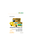
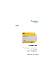
1
TM
User Manual
Isolated Power Panels
For Healthcare Facilities
NAE2095011 / 04.2013
TM
Bender Inc.
USA:
700 Fox Chase
Coatesville, PA 19320
Toll Free: 800-356-4266
Phone: 610-383-9200
Fax: 610-466-2071
E-mail: [email protected]
Canada:
5810 Ambler Drive, Unit 1
Mississauga, ON L4W 4J5
Toll Free: 800-243-2438
Phone: 905-602-9990
Fax: 905-602-9960
E-mail: [email protected]
Web: www.bender.org
NAE2095011, 04.2013
Replaces NAE2095010, 09.2010
© Bender Inc.
All rights reserved.
Content subject to change.
Table of Contents
1. Introduction.........................................................................................
1.1
General Description..........................................................................
1.1.1 Standard Isolated Power Panels (IP)...........................................
1.1.2 IP Panels with Receptacles And/Or Ground Jacks.................
1.1.3 IP Panels with Circuit Control........................................................
1.1.4 Dual Voltage Isolated Power Panels (ID)...................................
1.1.5 Dual System Isolated Power Panel (IX)......................................
1.2
Components .......................................................................................
1.2.1 Backbox Package...............................................................................
1.2.2 Interior Package.................................................................................
1.2.3 Isolation Transformers.....................................................................
1.2.4 Circuit Breakers ..................................................................................
1.2.5 Line Isolation Monitor (LIM) ..........................................................
1.2.6 Front Trim Package...........................................................................
1.2.7 Accessories Package.........................................................................
5
5
5
5
5
5
5
6
6
6
6
7
7
8
8
2. Safety Instructions............................................................................ 10
3. Receiving, Handling, and Storage ................................................. 12
3.1
Receiving............................................................................................ 12
3.2
Handling ............................................................................................. 12
3.3
Storage................................................................................................ 12
4. Installation ......................................................................................... 13
4.1
Support Requirements.................................................................. 13
4.2
Preparation and Assembly........................................................... 14
4.3
Backbox Mounting.......................................................................... 15
4.3.1 Backbox Mounting, Standard IP Panel .................................... 16
4.3.2 Backbox Mounting, IP Panel with Receptacles..................... 18
4.3.3 Backbox Mounting, IP Panel with Circuit Control ............... 20
4.3.4 Backbox Mounting, Dual System Panel (IX)........................... 22
4.3.5 Backbox Mounting, Dual Voltage Panel (ID) ......................... 24
4.4
Assembly ............................................................................................ 26
4.4.1 Assembly: Standard IP Panel, 3 kVA, 5 kVA............................ 27
Isolated Power Panels
© 2013 Bender Inc. All Rights Reserved
3
4.4.2
4.4.3
4.4.4
4.4.5
4.4.6
4.5
4.5.1
4.5.2
4.5.3
4.6
4.6.1
4.6.2
4.6.3
4.6.4
4.6.5
4.6.6
4.6.7
4.6.8
4.6.9
4.6.10
4.7
Assembly: Standard IP Panel, 7.5 kVA to 25 kVA .................
Assembly: IP Panel with Receptacles, 3 kVA to 10 kVA .....
Assembly: IP Panel with Circuit Control, 15 kVA, 25 kVA..
Assembly: Dual System Panel (IX) .............................................
Assembly: Dual Voltage Panel (ID)............................................
Transformer Installation ...............................................................
Vibration Pads and Mounting Hardware................................
Transformer Installation ...............................................................
Transformer Electrical Connections .........................................
Electrical Connections...................................................................
Wire Quality Requirements .........................................................
Grounding .........................................................................................
Additional Wiring Requirements: Fault Location ................
Additional Wiring Requirements: Remote Indicators........
Additional Wiring Requirements: Communication ............
Wiring: Standard IP Panel.............................................................
Wiring: IP Panel with Receptacles .............................................
Wiring: IP Panel with Circuit Control........................................
Wiring, Dual System Panel (IX) ...................................................
Wiring: Dual Voltage Panel (ID)..................................................
Final Inspection and Testing / Maintenance.........................
28
29
30
31
32
33
33
33
33
34
35
35
36
36
36
37
38
39
40
41
42
5. Operation and Settings................................................................... 43
5.1
Line Isolation Monitor ................................................................... 43
5.2
Operation of IP Panel with Circuit Control............................. 43
4
Isolated Power Panels
© 2013 Bender Inc. All Rights Reserved
Introduction
1. Introduction
1. 1
General Description
This document states how to install, operate, and maintain BENDER isolation
panels for hospital isolated power systems.
This document is for the use of qualified electricians. Refer to National Electric
Code (NEC) Article 517, National Fire Protection Association (NFPA) 99, and all
other applicable national and local codes and standards. Refer to Section 2 of
this document for other safety instructions.
The panel types included in this document are listed in the following sections.
1.1.1
Standard Isolated Power Panels (IP)
The standard isolation power panel is a single-voltage, single-system panel.
Contains one (1) LIM2010 Line Isolation Monitor (LIM).
1.1.2
IP Panels with Receptacles And/Or Ground Jacks
Contains the features of the standard isolated power panel, as well as provisions for power receptacles and/or ground jacks, located on the faceplate of
the panel.
1.1.3
IP Panels with Circuit Control
Contains the features of the standard isolated power panel, as well as circuit
interlock control via a programmable logic controller (PLC) and contactors.
1.1.4
Dual Voltage Isolated Power Panels (ID)
Provides two separate output voltages from one isolation transformer. Contains two (2) LIM2010 Line Isolation Monitors.
1.1.5
Dual System Isolated Power Panel (IX)
Provides two separate voltages from two isolation transformers. Contains two
(2) LIM2010 Line Isolation Monitors, as well as two sets of secondary branch
breakers. This system is equivalent to two independent IP panels in one enclosure.
Isolated Power Panels
© 2013 Bender Inc. All Rights Reserved
5
Introduction
1. 2
Components
The specifications listed below are standard for the United States unless otherwise noted. Contact the manufacturer for more information pertaining to custom orders. Ensure all purchased equipment obeys all national and local codes
and standards before purchasing.
1.2.1
Backbox Package
The backbox consists of a minimum 14 GA galvanized steel, flush- or surfacemounted piece. Flush mounting is standard. A request is required during the
purchasing process to the manufacturer for surface mounting. Surface
mounted backboxes are finished with a coat of hospital ivory baked enamel, or
equivalent.
1.2.2
Interior Package
The interior consists of a single component subpanel, containing a prewired
fixture plate, a dead front panel, and LIM2010 Line Isolation Monitor.
1.2.3
Isolation Transformers
Transformers for single isolated power panels, dual voltage isolated power
panel, and dual system isolated power panels provided by the manufacturer
have ratings which include 3, 5, 7.5, 10, 15, and 25 kVA. The fixed primary voltage for these transformers is in the range of 110 V to 480 V. The fixed secondary voltage for these transformers is in the range of 110 V to 240 V. The fixed
voltages are set at the manufacturer and depend on the specific equipment
requirements.
Transformers for isolated power panels with circuit control have ratings of 15
or 25 kVA. The fixed primary voltage for these transformers is in the range of
110 V to 480 V. The fixed secondary voltage is in the range of 110 V to 240 V.
The fixed voltages are set at the manufacturer and depend on the specific
equipment requirements.
6
Isolated Power Panels
© 2013 Bender Inc. All Rights Reserved
Introduction
1.2.4
Circuit Breakers
The primary circuit breakers installed in all panels are sized in accordance with
NFPA 70, Article 450-3(b)1(1). The quantity of secondary circuit breakers
installed varies by panel style:
•
Standard isolation power panels and isolation power panels with receptacles are factory installed with eight (8), 20 A secondary circuit breakers.
Panels are field-convertable up to sixteen (16) secondary circuit breakers
(the maximum allowed by UL).
•
Dual system panels are installed with two sets of eight (8), 20 A secondary
circuit breakers. Each system is field-convertable up to sixteen (16) secondary circuit breakers.
•
Isolated power panels with circuit control serve a maximum of eight (8)
secondary circuits. The number of secondary circuits, as well as which circuits receives power, is set at the factory.
•
For dual voltage panels, the 120 VAC side (“low” side) is installed with
eight (8) secondary circuit breakers, field expandable up to sixteen (16).
The 240 VAC side (“high” side) has either one (1) or two (2) secondary circuit breakers.
1.2.5
Line Isolation Monitor (LIM)
Each isolated power panel comes with one or more LIM2010 Line Isolation
Monitor (LIM) manufactured by BENDER. The function of the LIM is to monitor
the impedance to ground of the entire isolated power system. This value is
used to calculate the Total Hazard Current (THC), in units of milliamperes (mA).
The standard THC alarm value set at the factory is 5 mA. The value may be
switched to 2 mA to meet applicable certification requirements.
For more information on installation, settings, and operation of the LIM, refer
to the LIM2010 user manual, document NAE2025011.
Isolated Power Panels
© 2013 Bender Inc. All Rights Reserved
7
Introduction
1.2.6
Front Trim Package
The front trim for all panels is manufactured from minimum 14 GA, type 304
stainless steel. It contains a door with hidden hinges and a flush mounted key
lock. The front trim may be combined with a flush-mounted or surfacemounted backbox. For flush mounted panels, the front trim extends one inch
on all sides of the backbox. For surface mounted panels, the front trim has the
same height and width dimensions of the backbox.
1.2.7
Accessories Package
For information on installation and setup of optional accessories, refer to the
applicable documentation for each accessory.
8
Isolated Power Panels
© 2013 Bender Inc. All Rights Reserved
Introduction
This page intentionally left blank.
Isolated Power Panels
© 2013 Bender Inc. All Rights Reserved
9
Safety Instructions
2. Safety Instructions
!
DANGER
Hazard of Electric Shock, Burn, or Explosion
Only qualified maintenance personnel shall operate or service this equipment.
These instructions should not be viewed as sufficient for those who are not
otherwise qualified to operate or service this equipment. This document is
intended to provide accurate information only. No responsibility is assumed
by BENDER for any consequences arising from use of this document.
Turn OFF all sources of electric power before performing any inspections, tests,
or service on this equipment. Assume all circuits are live until they have been
properly de-energized, tested, grounded, and tagged. Failure to observe these
precautions will result in equipment damage, severe personal injury, or death.
Proper operation of this equipment depends on proper installation. Refer to
NFPA 99, NFPA 70E, CSA Z32, and other relevant standards and codes for installation standards. Neglecting fundamental installation techniques will result in
equipment damage, severe personal injury, or death.
Do not make any modifications to the equipment. Failure to observe this precaution will result in equipment damage or personal injury.
Use only manufacturer’s and manufacturer recommended accessories with
this equipment. Failure to do so may damage the equipment beyond repair.
10
Isolated Power Panels
© 2013 Bender Inc. All Rights Reserved
Safety Instructions
This page intentionally left blank.
Isolated Power Panels
© 2013 Bender Inc. All Rights Reserved
11
Receiving, Handling, and Storage
3. Receiving, Handling, and Storage
3. 1
Receiving
Verify details of purchase order before filing a shortage claim. Upon request,
backboxes may arrive first to allow sufficient time for contractors to fit panels
to their destination.
Inspection of the equipment should occur upon receipt of order. If damage or
mishandling is evident, a damage claim should be filed with the carrier immediately. The manufacturer’s local representative and field office should also be
notified of damages.
3. 2
Handling
Due to the very large weight of isolated power equipment, the use of equipment suitable for lifting and transporting heavy goods is necessary.
DANGER
Use equipment suitable for lifting and transporting
heavy loads. Failure to do so will result in equipment damage or severe personal injury.
3. 3
Storage
Isolated power equipment must not be stored in dusty or damp locations.
12
Isolated Power Panels
© 2013 Bender Inc. All Rights Reserved
Installation
4. Installation
4. 1
Support Requirements
Prior to installation of the panel, the weight of the equipment must be considered when selecting the correct structural support. The minimum load bearing requirements are listed below.
Panel Type
Weight (lb)
Weight (kg)
Standard IP panel, up to 10 kVA
300
136
Standard IP panel, 15 to 25 kVA
505
230
IP panel with receptacles
310
141
IP panel with circuit control
505
230
Dual voltage panel
560
255
Dual system panel
675
310
Isolated Power Panels
© 2013 Bender Inc. All Rights Reserved
13
Installation
4. 2
Preparation and Assembly
DANGER
Isolated power panels contain knockouts for additional circuit breakers. An electrical consultant must
be contacted before adding additional circuit
breakers. Failure to do so will result in severe personal injury or death.
Follow the general steps listed below to install an isolated power panel:
•
Mount the backbox. Refer to Section 4.3 for more information.
•
Install the interior package and any optional accessories into the backbox.
Refer to Section 4.4 for more information. NOTE: If the panel is fitted for
any accessory or accessories, the closure plate on the front trim must be
removed in order to complete the installation.
•
Install the isolation transformer. Refer to Section 4.5 for more information.
•
Install the electrical connections to the loads being served (receptacles,
surgical lighting, x-ray film viewers, etc.). See section 4.6 for more information.
•
Install deadfront panel and stainless steel trim panel.
14
Isolated Power Panels
© 2013 Bender Inc. All Rights Reserved
Installation
4. 3
Backbox Mounting
Sections 4.3.1 through 4.3.5 show possible placements for routing conduit and
fittings. Locate the drawing applicable to the panel being installed.
No knockouts or holes for conduit are provided in the backbox. Drilling excess
holes for non-standard mounting counting entrances is at the responsibility of
the installer. Front and rear backbox dimensions are the same.
Mounting hole location and size are at the discretion of the installer. Install the
backbox even with the finished wall or recess no more than 1/4” (6.35 mm).
The backbox should not protrude pas the finished wall.
Panel Type
Refer To
Standard IP Panel
page 16
IP Panel with Receptacles
page 18
IP Panel with Circuit Control
page 20
Dual System Panel (IX)
page 22
Dual Voltage Panel (ID)
page 24
Isolated Power Panels
© 2013 Bender Inc. All Rights Reserved
15
Installation
4.3.1
Backbox Mounting, Standard IP Panel
Legend and dimensions are located on the following page.
B
A
C
A
F
C
E
D
16
Isolated Power Panels
© 2013 Bender Inc. All Rights Reserved
Installation
Legend:
1
Stainless Steel Front Trim
9
Circuit Breaker: Main, 2P
2
Backbox, Galvanized Steel
10
Circuit Breaker: Branch, 2P
3
Backplate
11
Load Center
4
Backplate Mounting Studs
12
Isolation Transformer, 1Ph.
5
Transformer Shelf
13
Line Isolation Monitor, 1Ph.
6
Breaker Deadfront
14
LIM Connector Plate
7
Stainless Steel Door w/ Lock
15
Ground Bus
8
Distribution Block, 2P
Dimensions:
Dimensions are listed in inches (mm).
3, 5 kVA
7.5, 10 kVA
15 kVA
25 kVA
A
6” (152)
8” (203)
12” (305)
14” (356)
B
24” (610)
24” (610)
30” (762)
30” (762)
C
Flush: 1” (25)
Surface: 0” (0)
Flush: 1” (25)
Surface: 0” (0)
Flush: 1” (25)
Surface: 0” (0)
Flush: 1” (25)
Surface: 0” (0)
D
Flush: 45” (1143)
Surface: 43” (1092)
Flush: 45” (1143)
Surface: 43” (1092)
Flush: 53” (1346)
Surface: 51” (1295)
Flush: 53” (1346)
Surface: 51” (1295)
E
43” (1092)
43” (1092)
51” (1295)
51” (1295)
F
Flush: 26” (660)
Surface: 24” (610)
Flush: 26” (660)
Surface: 24” (610)
Flush: 32” (813)
Surface: 30” (762)
Flush: 32” (813)
Surface: 30” (762)
Isolated Power Panels
© 2013 Bender Inc. All Rights Reserved
17
Installation
4.3.2
Backbox Mounting, IP Panel with Receptacles
Legend and dimensions are located on the following page.
B
A
C
F
A
C
D
18
E
Isolated Power Panels
© 2013 Bender Inc. All Rights Reserved
Installation
Legend:
1
Stainless Steel Front Trim
10
Circuit Breaker: Branch, 2P
2
Backbox, Galvanized Steel
11
Load Center
3
Backplate
12
Isolation Transformer, 1Ph.
4
Backplate Mounting Bracket
13
Line Isolation Monitor, 1Ph.
5
Transformer Shelf
14
LIM Connector Plate
6
Breaker Deadfront
15
Ground Bus
7
Stainless Steel Door w/ Lock
16
Duplex Receptacle, Hosp. Grade
8
Distribution Block, 2P
17
Ground Jack, Hosp. Grade
9
Circuit Breaker: Main, 2P
18
Receptacle Hat Station
Dimensions:
Dimensions are listed in inches (mm).
3, 5, 7.5, 10 kVA
Isolated Power Panels
A
8” (203)
B
24” (610)
C
Flush: 1” (25)
Surface: 0” (0)
D
Flush: 50” (1270)
Surface: 48” (1219)
E
48” (1219)
F
Flush: 26” (660)
Surface: 24” (610)
© 2013 Bender Inc. All Rights Reserved
19
Installation
4.3.3
Backbox Mounting, IP Panel with Circuit Control
Legend and dimensions are located on the following page.
B
A
C
F
A
C
D
20
E
Isolated Power Panels
© 2013 Bender Inc. All Rights Reserved
Installation
Legend:
1
Stainless Steel Front Trim
11
Distribution Block, 2P
2
Backbox, Galvanized Steel
12
Isolation Transformer, 1Ph.
3
Backplate
13
Line Isolation Monitor, 1Ph.
4
Backplate Mounting Bracket
14
LIM Connector Plate
5
Transformer Shelf
15
Control Transformer w/ Fuses
6
Breaker Deadfront
16
Ground Bus
7
Stainless Steel Door w/ Lock
17
Programmable Logic Controller
8
Main Circuit Breaker, 2P
18
Terminal Block
9
Branch Circuit Breakers, @P
19
Circuit Contactors, 2P (M1-M8)
10
Provision for Expansion
20
Auxiliary Backplate
Dimensions:
Dimensions are listed in inches (mm).
15 kVA
25 kVA
A
12” (305)
14” (356)
B
30” (762)
30” (762)
C
Flush: 1” (25)
Surface: 0” (0)
Flush: 1” (25)
Surface: 0” (0)
D
Flush: 53” (1346)
Surface: 51” (1295)
Flush: 53” (1346)
Surface: 51” (1295)
E
51” (1295)
51” (1295)
F
Flush: 32” (813)
Surface: 30” (762)
Flush: 32” (813)
Surface: 30” (762)
Isolated Power Panels
© 2013 Bender Inc. All Rights Reserved
21
Installation
4.3.4
Backbox Mounting, Dual System Panel (IX)
Legend and dimensions are located on the following page.
B
A
C
F
A
C
E
D
22
Isolated Power Panels
© 2013 Bender Inc. All Rights Reserved
Installation
Legend:
1
Stainless Steel Front Trim (2 pc.)
10
Branch Circuit Breakers, 2P
2
Backbox, Galvanized Steel
11
Load Center
3
Backplate, Galvanized Steel
12
Line Isolation Monitor, 1Ph.
4
Backplate Mounting Bracket
13
LIM Connector Plate
5
Heat Shield
14
Ground Bus
6
Stainless Steel Door w/ Lock
15
Barriers Between Systems
7
Breaker Deadfront
16
Terminal Blocks
8
Distribution Block
17
Isolation Transformer, System A
9
Main Circuit Breaker, 2P
18
Isolation Transformer, System B
Dimensions:
Dimensions are listed in inches (mm).
5, 7.5, 10 kVA Per System
Isolated Power Panels
A
8” (203)
B
34” (864)
C
Flush: 1” (25)
Surface: 0” (0)
D
Flush: 53” (1346)
Surface: 51” (1295)
E
51” (1295)
F
Flush: 36” (914)
Surface: 34” (864)
© 2013 Bender Inc. All Rights Reserved
23
Installation
4.3.5
Backbox Mounting, Dual Voltage Panel (ID)
Legend and dimensions are located on the following page.
B
A
C
A
F
C
E
D
24
Isolated Power Panels
© 2013 Bender Inc. All Rights Reserved
Installation
Legend:
1
Stainless Steel Front Trim
9
Main Secondary Breaker, 2P
2
Backbox, Galvanized Steel
10
Branch Circuit Breakers, 2P
3
Backplate
11
Isolation Transformer,
Dual Secondary, 1Ph.
4
Backplate Mounting Bracket
12
Distribution Blocks
5
Transformer Shelf
13
Line Isolation Monitor, 1Ph.
Low Voltage Section
6
Breaker Deadfront
14
Line Isolation Monitor, 1Ph.
High Voltage Section
7
Stainless Steel Door w/ Lock
15
LIM Connector Plate
8
Main Primary Breaker, 2P
16
Ground Bus
Dimensions:
Dimensions are listed in inches (mm).
25 kVA
Isolated Power Panels
A
14” (356)
B
34” (864)
C
Flush: 1” (25)
Surface: 0” (0)
D
Flush: 53” (1346)
Surface: 51” (1295)
E
51” (1295)
F
Flush: 36” (914)
Surface: 34” (864)
© 2013 Bender Inc. All Rights Reserved
25
Installation
4. 4
Assembly
Sections 4.4.1 through 4.4.6 show assembly diagrams. Locate the drawing
applicable to the size and type of panel installed. For further information on
transformer installation, refer to section 4.5.
Panel Type
26
Refer To
Standard IP Panel - 3 kVA and 5 kVA
page 27
Standard IP Panel - 7.5 kVA to 25 kVA
page 28
IP Panel with Receptacles
page 29
IP Panel with Circuit Control
page 30
Dual System Panel (IX)
page 31
Dual Voltage Panel (ID)
page 32
Isolated Power Panels
© 2013 Bender Inc. All Rights Reserved
Installation
4.4.1
Assembly: Standard IP Panel, 3 kVA, 5 kVA
1
Backbox w/ Wide Panel Clip Nuts
6
#10 x 1.25” Oval Head Panel Screw
2
Interior Assembly
7
#10 Flanged Finishing Washer, SS
3
Front Trim Assembly
8
#4-40 Black Oxide Screws
4
Line Isolation Monitor
9
1/4”-20 Hex Lock Nut
5
Isolation Transformer
Isolated Power Panels
© 2013 Bender Inc. All Rights Reserved
27
Installation
4.4.2
28
Assembly: Standard IP Panel, 7.5 kVA to 25 kVA
1
Backbox w/ Wide Panel Clip Nuts
6
#10 x 1.25” Oval Head Panel Screw
2
Interior Assembly
7
#10 Flanged Finishing Washer, SS
3
Front Trim Assembly
8
#4-40 Black Oxide Screws
4
Line Isolation Monitor
9
1/4”-20 Hex Lock Nut
5
Isolation Transformer
Isolated Power Panels
© 2013 Bender Inc. All Rights Reserved
Installation
4.4.3
Assembly: IP Panel with Receptacles, 3 kVA to 10 kVA
1
Backbox w/ Wide Panel Clip Nuts
6
#10 x 1.25” Oval Head Panel Screw
2
Interior Assembly
7
#10 Flanged Finishing Washer, SS
3
Front Trim Assembly
8
#4-40 Black Oxide Screws
4
Line Isolation Monitor
9
1/4”-20 Hex Lock Nut
5
Isolation Transformer
Isolated Power Panels
© 2013 Bender Inc. All Rights Reserved
29
Installation
4.4.4
30
Assembly: IP Panel with Circuit Control, 15 kVA, 25 kVA
1
Backbox w/ Wide Panel Clip Nuts
6
#10 x 1.25” Oval Head Panel Screw
2
Interior Assembly
7
#10 Flanged Finishing Washer, SS
3
Front Trim Assembly
8
#4-40 Black Oxide Screws
4
Line Isolation Monitor
9
1/4”-20 Hex Lock Nut
5
Isolation Transformer
Isolated Power Panels
© 2013 Bender Inc. All Rights Reserved
Installation
4.4.5
Assembly: Dual System Panel (IX)
1
Backbox w/ Wide Panel Clip Nuts,
Barriers, and Terminal Blocks
6
Isolation Transformer
2
Interior Assembly w/ Barrier
7
#10 x 1.25” Oval Head Panel Screw
3
Front Trim Assembly, Upper Section
8
#10 Flanged Finishing Washer, SS
4
Front Trim Assembly, Lower Section
9
#4-40 Black Oxide Screws
5
Line Isolation Monitor
10
1/4”-20 Hex Lock Nut
Isolated Power Panels
© 2013 Bender Inc. All Rights Reserved
31
Installation
4.4.6
32
Assembly: Dual Voltage Panel (ID)
1
Backbox w/ Wide Panel Clip Nuts
6
#10 x 1.25” Oval Head Panel Screw
2
Interior Assembly
7
#10 Flanged Finishing Washer, SS
3
Front Trim Assembly
8
#4-40 Black Oxide Screws
4
Line Isolation Monitor
9
1/4”-20 Hex Lock Nut
5
Isolation Transformer
Isolated Power Panels
© 2013 Bender Inc. All Rights Reserved
Installation
4. 5
Transformer Installation
All transformers must be installed into the panel at the end location.
4.5.1
Vibration Pads and Mounting Hardware
Mounting hardware is provided with each transformer. The hardware includes
vibration pads. Install hardware in accordance to the appropriate diagram
below. Do not compress the vibration pads. If compressed, the pads may not
dampen noise.
Dual System Panels
All Other Panels
4.5.2
Transformer Installation
Isolation transformers may weigh up to 500 lb (1100 kg), and require special
handling. Depending on the isolated power panel design, the transformer(s)
may be installed in either the top half or bottom half of the enclosure. Refer to
the appropriate assembly drawing in section 4.4, as well as the approved submittal drawings for the specific locations. If located in the top half of the enclosure, place transformer on transformer shelf provided with the panel. If located
in the bottom half of the panel, place the transformer on the provided studs.
Orient the transformer(s) in the enclosure to allow the leads to extend from
the front to facilitate the process of wiring the primary circuit breaker and load
center.
4.5.3
Transformer Electrical Connections
Refer to Section 4.6 for information on making electrical connections to the
isolation transformer(s).
Isolated Power Panels
© 2013 Bender Inc. All Rights Reserved
33
Installation
4. 6
Electrical Connections
Sections 4.4.6 through 4.4.10 show specific connections for isolated power
panels. Locate the drawing specific to the type of panel being installed.
DANGER
- This equipment must be installed and serviced
only by qualified electrical personnel.
- Turn off all sources of power before servicing.
- Do not use wire pulling lubricant of any type on
secondary circuits.
- Conduit must be clean and dry.
- Maintain identical phasing throughout the installation.
- Replace all devices, doors, and covers before powering the equipment.
Failure to do so will result in severe personal injury
or death.
Electrical connections required on site are as follows:
•
Connection of main power feeders
•
Connection of reference ground bus to ground lug on terminal board, if
not factory installed
•
Connection of remote indicator(s) to the Line Isolation Monitor, if required
•
Connection of secondary circuits to the conductors or panel board circuit
breakers on the sub-panel. The contactors are marked and have lugs to
ease connecting. The specifier or consulting engineer chooses the proper
wire size.
The color coding of the secondary circuit conductors, in accordance with NFPA
70, Article 517, are as follows:
•
Isolated conductor no. 1: Orange with at least one distinctive colored
stripe OTHER THAN white, green, or gray along the entire length of the
conductor
•
Isolated conductor no. 2: Brown with at least one distinctive colored stripe
OTHER THAN white, green, or gray along the entire length of the conductor
•
Equipment grounding conductor: Green with or without yellow stripe
34
Isolated Power Panels
© 2013 Bender Inc. All Rights Reserved
Installation
4.6.1
Wire Quality Requirements
BENDER recommends using cross-linked, polyethylene wire with a dielectric
constant of 3.5 or less. The most widely available wire for this application is
low-leakage wire type XHHW or XHHW-2.
Avoid wire with high carbon fiber filler, as this produces substantial leakage in
an isolated power system. Ensure the wire is the appropriate size for the transformer and meets national and local code requirements.
4.6.2
Grounding
DANGER
Before proceeding, read this section, all wiring diagrams, and all applicable code requirements to
thoroughly understand the special requirements for
grounding this type of system. Failure to do so will
result in severe injury or death.
Isolated power systems for healthcare facilities are not grounded in the same
manner as many other types of electrical equipment. They have special
grounding requirements to reduce electrical hazards to patients and staff. The
reference grounding point is NOT the earth ground or neutral conductor. The
ground bus in the isolation panel is the reference grounding point for the
room, as defined by NFPA 70, Article 517.
Use only one conductor to connect the reference ground bus in the isolated
power panel to the ground bar of the facility’s main grounding system. The
main grounding system is the distribution panel that feeds power to the isolated power panel. Connect all green ground conductors from the equipment
in the patient care area served by the isolated power panel to the ground bus
of that panel.
If more than one isolated power panel serves the same area, refer to NFPA 70,
Article 517.14 for grounding requirements.
To ground transformers, connect a green ground conductor from the lug on
the electrostatic shield of the transformer to the reference ground bus of the
isolated power panel.
Isolated Power Panels
© 2013 Bender Inc. All Rights Reserved
35
Installation
4.6.3
Additional Wiring Requirements: Fault Location
If ground fault location has been preinstalled in the interior, terminal blocks for
landing the secondary circuits are provided. For panels without installed
ground fault location, secondary circuits are landed on the contactors or panel
board circuit breakers as noted in Section 4.4.
The required RS-485 connections for ground fault location for a single panel
are pre-wired to the LIM2010 connector plate at the factory.
4.6.4
Additional Wiring Requirements: Remote Indicators
This section applies to MK2000 series remote indicators. Refer to the installation bulletin for the appropriate remote indicator for additional wiring requirements for installing the remote indicator.
4.6.5
Additional Wiring Requirements: Communication
Additional RS-485 wiring may be required when one or more panels are connected to each other for one of the following reasons:
•
Connecting to MK2430 / MK800 remote indicating station
•
Connecting to COM460IP communication module for Ethernet or Modbus/TCP communication
•
Connecting to FTC470XMB communication module for Modbus/RTU
communication
RS-485 connections will be required at the LIM2010 connector plate located in
the interior. For more information on setting up RS-485 communication for
medical panels, refer to LIM2010 user manual, as well as the user manual for
the respective communication device.
36
Isolated Power Panels
© 2013 Bender Inc. All Rights Reserved
Installation
4.6.6
Wiring: Standard IP Panel
Isolated Power Panels
© 2013 Bender Inc. All Rights Reserved
37
Installation
4.6.7
Wiring: IP Panel with Receptacles
NOTE: Typical schematic. Quantity of receptacles and ground jacks may vary
by application.
38
Isolated Power Panels
© 2013 Bender Inc. All Rights Reserved
Installation
4.6.8
Wiring: IP Panel with Circuit Control
NOTE: Typical schematic. Quantity of circuits controlled by PLC may vary by
application. Connections may vary when controlled by selector.
Isolated Power Panels
© 2013 Bender Inc. All Rights Reserved
39
Installation
4.6.9
40
Wiring, Dual System Panel (IX)
Isolated Power Panels
© 2013 Bender Inc. All Rights Reserved
Installation
4.6.10 Wiring: Dual Voltage Panel (ID)
Isolated Power Panels
© 2013 Bender Inc. All Rights Reserved
41
Installation
4. 7
Final Inspection and Testing / Maintenance
NFPA 99 requires testing of isolated power systems prior to placing them into
service and at regular intervals thereafter. Warranty shall not be issued on isolated power panels unless final inspection and testing has been conducted by
an authorized manufacturer representative.
BENDER recommends testing isolated power systems not less than once every
twelve months. The testing is intended to maintain the minimum levels as
described in NFPA 99. Testing should be both resistive and capacitive to verify
proper functionality of the Line Isolation Monitor.
BENDER further recommends pressing the TEST button not less than once a
month to verify proper operation of the Line Isolation Monitor.
Consult your local representative or the manufacturer for more information.
42
Isolated Power Panels
© 2013 Bender Inc. All Rights Reserved
Operation and Settings
5. Operation and Settings
5. 1
Line Isolation Monitor
Refer to LIM2010 user manual, document, NAE2025011, for additional information on installing, setting, and operating the Line Isolation Monitor.
5. 2
Operation of IP Panel with Circuit Control
IP panels with circuit control are designed to provide power to portable equipment outlets, such as surgical lasers. Multiple branch circuits may be controlled from this type of panel. The configuration of which circuits receive
power is configured at the factory. No power will be delivered to a secondary
circuit until the secondary breaker is closed.
A BENDER XRM series receptacle module is shown below, with door contactenabled circuit control.
Isolated Power Panels
© 2013 Bender Inc. All Rights Reserved
43
Operation and Settings
This page intentionally left blank.
44
Isolated Power Panels
© 2013 Bender Inc. All Rights Reserved
Operation and Settings
This page intentionally left blank.
Isolated Power Panels
© 2013 Bender Inc. All Rights Reserved
45
Operation and Settings
This page intentionally left blank.
46
Isolated Power Panels
© 2013 Bender Inc. All Rights Reserved
TM
Bender Inc.
USA:
700 Fox Chase
Coatesville, PA 19320
Toll Free: 800-356-4266
Phone: 610-383-9200
Fax: 610-466-2071
E-mail: [email protected]
Canada:
5810 Ambler Drive, Unit 1
Mississauga, ON L4W 4J5
Toll Free: 800-243-2438
Phone: 905-602-9990
Fax: 905-602-9960
E-mail: [email protected]
Web: www.bender.org