1
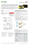
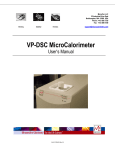
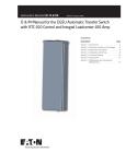
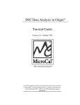
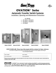
EDS3090 Series
Installation Bulletin / Reference Guide
This document is intended as a reference guide for installing and using a BENDER EDS3090 series
ground fault location system for ungrounded systems. This document includes installation, setup,
and usage instructions. For complete details, including installation, setup, settings, and troubleshooting, refer to the EDS3090 user manual, document number TGH1454en. This document is intended as a
supplement and not a replacement to the complete user manual.
Only qualified maintenance personnel shall operate or service this equipment. These instructions
should not be viewed as sufficient for those who are not otherwise qualified to operate or service this
equipment. This document is intended to provide accurate information only. No responsibility is assumed by BENDER for any consequences arising from use of this document.
General Information
General Procedure For Use (Cont’d)
Application
This documentation applies to the following versions of the EDS3090 series and their contents:
Step 1B - Correct Settings on IRDH575 (kits not ending in “PG” only)
Systems that do not end in “PG” (Including part numbers EDS3090 and EDS3091) require an
IRDH575 ground detector be installed in the system. The IRDH575 includes the pulse generator function normally included with PGH183/PGH185 devices.
Under menu option “EDS SETUP,” ensure the following settings are correct:
•
•
•
EDS3090 and EDS3091 (requires IRDH575/LIM2010 detector already installed in system)
EDS3090PG and EDS3090PG-13 (standalone)
EDS3091PG and EDS3091PG-13 (standalone)
Refer to the complete user manual for information on other models and variants.
Ensure all components of the kit are correct. Refer to table on reverse side for list of components for each kit.
•
Menu option “EDS”: Set to auto.
•
System: Set this to the correct type of system the device is on. For instance, for Threephase AC systems, select “3AC.” For DC systems, select “DC.”
•
MaxPuls: This setting must correspond to the type of kit being used. For EDS3090 systems, this must be set to 10 or 25 mA. For EDS3091 kits, this must be set to 1 or 2.5 mA.
Important System Requirements
Refer to the complete user manual for technical information regarding requirements for proper
ground fault location, response characteristics, and other general use information not mentioned in this document.
Refer to IRDH575 user manual for more information.
Two different types of portable ground fault location systems exist. The EDS3090 kit is designed
to be used with a BENDER IRDH575 ground detector that is already installed in the system.
The EDS3091kit is designed to be used with a BENDER IRDH575 or LIM2010 already installed
in the system. All EDS3090 kits ending in “PG” are designed to be standalone and do not require any other devices installed in the system. EDS3091PG models are designed for locating
ground faults in small, low-voltage systems, such as control networks and healthcare facilities.
EDS3090PG models are designed for medium to large scale distribution networks.
•
Set operation mode to I∆s.
•
Select the correct clamp. For the PSA3020 or PSA3320, select “P20.” For the PSA3052 or
PSA3352, select “P52.” For the PSA3165, select “P165.”
•
Connect the appropriate clamp.
How It Works
A measuring signal is generated and superimposed on the system. When using the EDS3090,
this signal is generated by the IRDH575 automatically after a ground fault is detected. When using a model ending in “PG,” the signal is generated manually by the PGH series pulse generator
installed in the system.
The measuring signal naturally travels through the ground fault, back to the source of the pulse
generation. Using the EDS195P hand-held meter and appropriate clamp, the signal is traced
down to the source of the ground fault.
Step 2 - Set up EDS195P hand-held meter
Below are the basic settings required for operation:
Refer to the reverse side of this document for more information on using the EDS195P.
Step 3 - Begin ground fault location
Figure 2 below is a typical ground fault location schematic. Follow the general procedures
below. NOTE: The steps below are for general applications, and some systems may require different procedures. Consult the manufacturer for more information.
General Procedure For Use
Step 1A - Install the pulse generator (kits ending in “PG” only)
Only follow this step if using a kit ending in “PG” and an
IRDH575 is NOT already installed in the system. Otherwise,
go to step 1B.
Kits ending in “PG” come with a PGH series pulse genera- HAZARD OF ELECTRIC SHOCK,
tor kit. This kit must be installed in the circuit as far up- EXPLOSION, OR ARC FLASH
stream as possible, in order to ensure all branches are
included in the fault location. When using the PGH185, • Disconnect all power before servicing.
voltages higher than 575 VAC or 504 VDC require an ad- • Observe all local, state, and national
ditional AGE185 voltage coupler.
codes, standards, and regulations.
Connect the PGH series pulse generator as follows. Use
the supplied cables and connectors for connections.
! DANGER
•
EDS195P
ISOSCAN®
PGH18x
RF
GND
Figure 2 - Ground fault location on an ungrounded three-phase AC system
Connect system connections:
•
Single-phase AC: Connect L1 and L2 to the system phases.
•
Three-phase AC: Connect L1, L2, and L3 to the three phases of the system.
•
DC: Connect L1 to system positive, L2 to system negative.
•
Connect ground connection to the system’s equipment ground.
•
Connect US to control power (90...132 VAC for “-13” models, 230 VAC for others)
1
6
2
Begin the pulse generation. Systems with IRDH575 devices should begin this automatically. Systems with PGH series pulse generators require pressing the power switch to the
ON position.
2.
Clamp around the ground wire connected to the IRDH575 / PGH series module. If a
ground fault is present in the system, a visual and audible alarm should be present, reading the full magnitude of the tracer signal.
3.
Begin at the appropriate branching point, such as a motor control center or loadcenter.
The starting point must use cabling that is small enough to have all branch conductors
passing through the clamp.
1.
ON/OFF switch
2.
Pulse magnitude switch (10/25
mA for PGH185, 1/2.5 mA for
PGH183)
4.
Go to branch 1. Clamp around all branch conductors.
5.
Wait approximately 10 seconds. If no alarm activates, or no signal is detected, move to the
second branch. Repeat for all branch circuits until an alarm is activated.
3.
System connections
6.
4.
Equipment ground connection
If the alarm activates and the tracer signal is measured, follow the branch downstream
to the load or next branch. If the circuit branches once again, repeat steps 3 through 6.
5.
LED indicators: POWER on, positive cycle of signal, negative cycle
of signal
6.
Plug for supply voltage (90...132
VAC for “-13” models, 230 VAC for
others)
5
4
1.
3
Figure 1 - PGH185 / PGH183 pulse generator
Bender Inc. • USA: 800.356.4266 / 610.383.9200 / [email protected] • Canada: 800.243.2438 / 905.602.9990 / [email protected] • www.bender.org
Document NAE1018031 • 08.2013 • © Bender Inc. • Page 1/1 • Side 1/2
EDS3090 Series
Installation Bulletin / Reference Guide
EDS195P Handheld Meter
Menu Structure Flow Chart
1
2
EDS195P
ISOSCAN
®
3
4
5
10
11
6
7
8
OK
12
The flow chart below shows the structure of the menu built into the EDS195P. The menu is
used for making any necessary settings changes and viewing harmonics when in I∆n mode.
Use the supplied gray boxes to take note of applied settings for future reference.
1.
MicroUSB port for charging
2.
Clamp connector
3.
LCD display
4.
Alarm LED
5.
Operation mode pushbutton:
Select I∆s for ground fault location mode.
6.
Clamp selection pushbutton
7.
INFO button: Displays system and
device information
8.
MENU / ENTER button: Opens the
device’s main menu on the display / Confirms in main menu
1. EXIT
9.
POWER button
2. Settings
Menu or settings option
Settings option essential for proper operation
10. HOLD / UP button: Freezes measured value / moves up in the device’s main menu
1. Exit
2. General
11. RESET / DOWN button: Resets
held value / moves down in device’s main menu
12. Illumination button: Toggles backlight on display
3. IΔs
9
4. IΔn
EDS195P: Display
5.System
1
12
11
2
3. Harmonics
1. Exit
2. Memory
on
off
3. Buzzer
on
off
4. AlarmLED
on
off
5. ItMax
5mA
50mA
1. Exit
2. Resp.
2...10 mA
200...1000 μA
3. System
AC
DC
4. Inverter
yes
no
1. Exit
2. Resp
10 mA ... 10 A
3. Freq
50Hz 60Hz
Up to 2kHz
4. Harmonics
on
off
1. Exit
2. Language
English
French
German
3. Clock
00:00 ... 23:00
1. Exit
2. H1 = X mA
. . .
10
9
8
7
6
5
3
4
10. H9 = X mA
1.
Progress bar, active during fault location
8.
Lights when alarm status is latched
(fault memory)
2.
Indication of tracer signal: Positive
peak, idle, negative peak
9.
Indicates selected clamp / CT
3.
System type (AC / DC)
4.
Lights when hold activated (measured
value is frozen)
11. Real-time measured value of ground
fault current (usable in grounded systems - I∆n mode)
5.
Battery life remaining
6.
Lights when alarm LED output is active
7.
Visible when audible alarm is activated
in menu
4. Service
10. Indicates EDS system type (see below)
12. Magnitude of tracer signal, if measured
(standard operating mode - I∆s mode)
Scope of Delivery
Using the EDS195P on Grounded Systems
The EDS195P and clamps may additionally be used for ground fault current monitoring on
grounded AC systems. To conduct measurements, the following steps are required:
•
Set operation mode to I∆s.
•
Select the correct clamp. For the PSA3020 or PSA3320, select “P20.” For the PSA3052 or
PSA3352, select “P52.” For the PSA3165, select “P165.”
•
If desired, an alarm level may be set to activate the audible and visual alarms. This value
may be set under the menu option SETTINGS > I∆n > RESP. If this value is not set, the currently read value will still display on the main screen of the EDS195P.
•
Connect the appropriate clamp.
•
Clamp around all branch conductors until a reading is displayed on the main screen.
Use the table below to ensure all components of the kit are correct.
Hand-held
evaluator
Current
generator
EDS195P
EDS195P
EDS195P
EDS195P
EDS195P
EDS195P
EDS195P
EDS195P
–
PGH185
PGH185-13
PGH186
PGH186-13
–
PGH183
PGH183-13
PGH supply
voltage
20 mm
clamp
52 mm
clamp
Type
230 V (50/60 Hz)
120 V (50/60 Hz)
230 V (50/60 Hz)
120 V (50/60 Hz)
–
230 V (50/60 Hz)
120 V (50/60 Hz)
PSA3020
PSA3020
PSA3020
PSA3020
PSA3020
PSA3320
PSA3320
PSA3320
PSA3052
PSA3052
PSA3052
PSA3052
PSA3052
PSA3352
PSA3352
PSA3352
EDS3090
EDS3090PG
EDS3090PG-13
EDS3096PG
EDS3096PG-13
EDS3091
EDS3091PG
EDS3091PG-13
Technical Data
Refer to EDS3090 series user manual (document TGH1420en) or EDS3090 series datasheet (document NAE1012031) for detailed technical information on EDS3090 systems and components.
Bender Inc. • USA: 800.356.4266 / 610.383.9200 / [email protected] • Canada: 800.243.2438 / 905.602.9990 / [email protected] • www.bender.org
Document NAE1018031 • 08.2013 • © Bender Inc. • Page 1/1 • Side 2/2