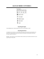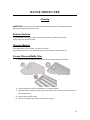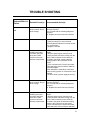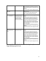
1
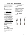
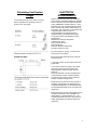
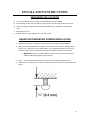
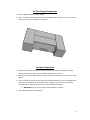
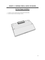
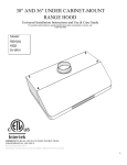
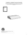
UNDER CABINET RANGE HOOD
Universal Installation Instructions and Use & Care Guide
For questions about features, operation/performance parts, accessories or service, call:
1-626-453-0550
Model:
Y01
W01
IMPORTANT: READ AND SAVE THESE INSTRUCTIONS.
FOR RESIDENTIAL USE ONLY.
Revised September 2014
Disclaimer: Item purchased may be slightly different from the manual.
1
TABLE OF CONTENTS
RANGE HOOD SAFETY ....................................................................2
INSTALLATION REQUIREMENTS ...................................................4
Tools and Parts Requirements ...................................................4
Location Requirements .............................................................4
Installation Dimensions ............................................................5
Ventilation Requirements .........................................................6
Electrical Requirements ............................................................7
INSTALLATION INSTRUCTIONS ..................................................8
Prepare Location ......................................................................8
Connect Vent System ..............................................................10
Complete Installation ..............................................................11
Electrical Connection ……………………………………………..12
RANGE HOOD USE .........................................................................13
Range Hood Controls ..............................................................14
RANGE HOOD CARE ......................................................................15
Cleaning .................................................................................15
Replacement ...........................................................................16
TROUBLE SHOOTING ...................................................................17
WARRENTY & SERVICES .............................................................19
RANGE HOOD SAFETY
Your safety and the safety of others are very important.
We have provided many important safety messages in this manual and on your appliance. Always read and obey all safety
messages.
This is the safety alert symbol.
This symbol alerts you to potential hazards that can kill or hurt you and others.
All safety messages will follow the safety alert symbol and either the word “DANGER” or “WARNING.”
These words mean:
DANGER
WARNING
You can be killed or seriously injured if you don't immediately
follow instructions.
You can be killed or seriously injured if you don't follow
instructions.
2
IMPORTANT SAFETY INSTRUCTIONS
WARNING: TO REDUCE THE RISK OF FIRE, ELECTRIC
SHOCK, OR INJURY TO PERSONS, READ THE
FOLLOWING:
■ Use this unit only in the manner intended by the
manufacturer. If you have questions, please
contact the manufacturer.
■ Before servicing or cleaning the unit, switch the power off
and lock the service panel. This will prevent the power
from accidentally turning on. If the service panel does not
lock, secure a warning label, such as a tag, to the service
panel.
■ Installation work and electrical wiring must be done by a
qualified professional(s) in accordance with all applicable
codes, standards, and fire-rated constructions.
■ Do not operate any fans with a damaged cord or plug.
Discard the fan or return to an authorized service
facility for further examination and/or repair.
■ To prevent back draft, sufficient air is needed for
proper combustion. Gas from fuel burning equipment
needs to exhaust through the flue (chimney). Follow the
heating equipment manufacturer's guideline and safety
standards such as those published by the National Fire
Protection Association (NFPA), the American Society
for Heating, Refrigeration and Air Conditioning
Engineers (ASHRAE), and the local code authorities.
■ When cutting or drilling into walls or ceilings; be aware of
electrical wires, piping, and other utilities.
■ Ducted fans must always be vented outdoors.
CAUTION: For general ventilation use only. Do not use
to exhaust hazardous or explosive materials and vapors.
CAUTION: To reduce the risk of fire and to properly
exhaust air, be sure to duct air outside - DO NOT vent
exhaust air into attics, crawl spaces, garages, or within
walls and ceilings.
WARNING: TO REDUCE THE RISK OF A RANGE TOP
GREASE FIRE, READ THE FOLLOWING:
■ Never leave surface units unattended at high settings.
Boil-over can cause smoke and grease to spill over that
may ignite. Heat oils slowly on low or medium settings.
■ Always turn the hood ON when cooking at high heat or
when flambéing food (i.e. Crepes Suzette, Cherries
Jubilee, Peppercorn Beef Flambé).
■ Clean ventilation fans frequently. Grease should not be
allowed to accumulate on fan or filter.
■ Use proper pan size. Always use cookware
appropriate for the size of the surface element.
WARNING: TO REDUCE THE RISK OF INJURY. IN
THE EVENT OF A RANGE TOP GREASE FIRE, READ
THE FOLLOWING:
■ SMOTHER FLAMES with a close fitting lid, cookie sheet, or
metal tray, then turn off the burner. BE CAREFUL TO
PREVENT BURNS. If the flames do not go out immediately,
EVACUATE AND CALL THE FIRE DEPARTMENT.
■ NEVER PICK UP A FLAMING PAN - you may be burned.
■ DO NOT USE WATER, including wet dishcloths or towels a violent steam explosion will result.
■ Use an extinguisher ONLY if:
– You know you have a class ABC extinguisher, and you
already know how to operate it.
– The fire is small and contained in the area where it
started.
– The fire department is being called.
– You can fight the fire with your back to an exit.
Based on "Kitchen Fire Safety Tips" published by NFPA.
■ WARNING: To reduce the risk of fire or electrical shock,
do not use this fan with any solid-state speed control
device.
3
INSTALLATION REQUIREMENT
TOOLS AND PARTS
REQUIREMENTS
Electrical drill or ratchet driver
1/2” drill bit for drilling pilot holes
1 ¼” drill bit for drilling electrical wiring access
hole.
Screwdrivers: Philips & Straight blade
Pliers
Tape measure or ruler and pencil
Electrical supplies for wiring
Aluminum foils tape and/or duct tape
Hammer
Jigsaw or saber saw
Stud finder
Parts Supplied
Body
1 Pc
Installation manual
1 Set
Metal filter
1-4 Pcs
Air outlet
1 Set
Exhaust pipe
1 Pc
Hardware
1 Set
LOCATION REQUIREMENTS
IMPORTANT: Observe all governing codes
and ordinances. Have a qualified technician
install the range hood. It is the installer’s
responsibility to comply with installation
clearances specified on the model/serial
rating plate.
Canopy hood's location should be away from
strong draft areas, such as windows, doors, and
strong heating vents.
Cabinet opening dimensions that are shown must
be used. Given dimensions provide minimum
clearance.
Disclaimer: Screws many vary from model to
model.
4
INSTALLATION DIMENSIONS
A.
B.
C.
D.
Countertop height
Hood height from ceiling to bottom of the range hood filter surface: D-A-C=B
29” (73.66 cm) min. from cooking surface, suggested 31” (78.74 cm) max.
Ceiling height
5
VENTILATION REQUIREMENTS
■ Range hoods must be ventilated to the
outdoors
■ Do not ventilate the range hood into an
attic or other enclosed areas.
■ Do not use 4" (10.2 cm) laundry-type wall
caps.
■ The length of the range hood and the
number of elbows should be kept to a
minimum to provide maximum performance.
For the most efficient and
quiet operation
■ Use no more than three 90°elbows.
■ Make sure there is a minimum of 24" (61
cm) of straight duct between the elbows if
more than one elbow is used.
■ Do not install two elbows together.
■ Use clamps to seal all joints in the vent
system.
■ The vent system must have a damper. If
the roof or wall cap has a damper, do not
use the damper supplied with the range
hood.
■ Use caulking to seal exterior walls or roof
openings around the cap.
■ The size of the vents should be uniform.
Venting Method
This canopy hood is factory set for through
the roof or wall.
A 6" (15.2 cm) round vent system is needed
for installation. The hood exhaust opening is
6" (15.2 cm) round.
To vent through a wall, a 90°elbow is
needed.
If exhaust ducting with a diameter of less
than 5.91” (150 mm) or if flat ducting is used,
the noise level of the range hood will
increase and extraction will be less efficient.
Rear Discharge
A 90°elbow may be installed immediately
above the hood.
Cold Weather Installations
An additional back draft damper should be
installed to minimize backward cold air flow.
A thermal break should be installed to
minimize conduction of outside temperatures as part of the vent system. The
damper should be on the cold air side of the
thermal break.
The break should be as close as possible to
where the vent system enters the heated
portion of the house.
Makeup Air
Local building codes may require the use of
makeup air systems, when using ventilation
systems greater than specified CFM of air
movement. The specified CFM varies from
state to state. Consult your HVAC
professional for specific requirements in
your area.
6
Calculating Vent System
Length
To calculate the length of the system you need,
add the equivalent feet (meters) for all vent
pieces used in the system.
ELECTRICAL
REQIUREMENTS
Observe all governing codes and ordinances.
Ensure that the electrical installation is adequate
and in conformance with the National Electrical
Codes, ANSI/NFPA 70 (latest edition), or CSA
Standards C22.1-94, Canadian Electrical Code,
Part 1 and C22.2 No. 0-M91 (latest edition), all
local codes, and ordinances. If codes permit and
a separate ground wire is used, it is
recommended that a qualified electrician
determine that the ground path is adequate.
A copy of the above code standards can be
obtained from:
National Fire Protection Association
1 Batterymarch Park
Quincy, MA 02169-7471
CSA International
8501 East Pleasant Valley Road
Cleveland, OH 44131-5575
■ A 120 volt, 60 Hz., AC only, 15-amp, fused
electrical circuit is required.
■ If the house has aluminum wiring, follow the
procedure below:
1. Connect a section of solid copper wire to the
pigtail leads.
2. Connect the aluminum wiring to the copper
wire using special connectors and/or tools
designed and UL listed for joining copper to
aluminum.
Follow the electrical connector manufacturer's
recommended procedure. Aluminum/copper
connection must conform to local codes and
industry accepted wiring practices.
■ Wire sizes and connections must conform to
the rating of the appliance as specified on the
model/serial rating plate. The model/serial plate
is located behind the filter on the rear wall of the
range hood.
■ Wire sizes must conform to the requirements of
the National Electrical Code, ANSI/NFPA 70
(latest edition), or CSA Standards C22. 1-94,
Canadian Electrical Code, Part 1 and C22.2 No.
0-M91 (latest edition) and all local codes and
ordinances.
7
INSTALLATION INSTRUCTIONS
PREPARING THE LOCATION
■
It is recommended for the vent system to be installed before hood is installed.
■
Before making cutouts, make sure there is proper clearance from the range hood to the cook top.
■
Check your cabinet’s height and the hood height available for your ceiling before selecting your
hood.
1.
Disconnect the power.
2.
Determine which venting method to use: roof, wall, or back.
RANGE HOOD MOUNTING SCREWS INSTALLATION
1.
Determine and mark the centerline on the cabinet where the range hood will be installed.
2.
Select a mounting height between a minimum of 27” (68.6cm) ) for an electric cooking surface, a
minimum of 27” (68.6cm) for a gas cooking surface, and a suggested maximum of 36” (91.4cm)
above the cooking range to the bottom of the range hood. Mark a reference line on the wall.
a.
IMPORTANT: All screws must be installed into wood. If there is no wood to screw into,
additional wall framing supports may be required.
3.
Drill ³⁄₁ ₆ " (4.8 mm) pilot holes at all locations where screws are being installed into wood.
4.
Install 4 M5 x 45 mounting screws under the cabinet and 4 M5 X12 screws in the inner sides of the
cabinet.
8
Air Flow Flapper Preparation
5.
Mark the flappers location under the cabinet.
6.
Cut out a rectangle a little bit larger than the air flow flapper under the cabinet. Also, cut out a circle
where the white, green, and black wires would be.
Complete Preparation
1.
Determine and make all necessary cuts in the wall for the vent system. Install the vent system
before installing the hood. See Page 6 “Ventilation Requirements” Section.
2.
Determine the required height for the home power supply cable and drill a 1¼" (3.2 cm) hole at this
location.
3.
Run the home power supply cable according to the National Electrical Code or CSA Standards and
local codes and ordinances. There must be enough conduits (½") and wires from the fuse box
(circuit breaker) to make the connection in the hood’s electrical terminal box.
a.
4.
IMPORTANT: Do not reconnect power until installation is complete.
Use caulking sealant to seal all openings.
9
STEP 1: CONNECTING VENT SYSTEM
Air Flow Flapper Installation
1.
Install the non-return air flap on top of hood with M5 X 8 screws (Part B).
2.
Remove the tape from the air flow flappers. (Part C)
10
STEP 2: MOUNTING THE RANGE HOOD
1.
After preparing the location, use two or more people, hang the range hood on the 8 mounting
screws (Part A), installed during preparations (Look at page 8), through the mounting slots on the
top of hood (Part B1).
Excessive Weight Hazard
Use two or more people to move and install range hood.
Failure to do so can result in back or other injury.
2.
Level the range hood and tighten inner M5 X 45 mounting screws (Part B2).
3.
Tighten the 4 M5 X 12 screws after (Part C).
11
STEP 3: ELECTRICAL CONNECTION
1.
Connect the three prong cable (not included) to the existing cable on the range hood.
2.
Connect the White to White, Black to black, and Green ground to green ground by either a solder
or with a connection piece.
DO NOT FORGET TO GROUND THE CONNECTION
SAFETY WARNING: Risk of electrical shock. This range hood must be properly grounded. Make sure this is
done by a qualified electrician in accordance with all national and local electrical codes. Before connecting
the wires, switch the power off at the service panel and lock the service panel to prevent power from being
switched on accidentally.
12
RANGE HOOD USE
The range hood is designed to remove smoke, vapors, and odors. For best results, start the hood before
cooking. After, the cooking process is complete, allow the range hood to run for several minutes to
completely clear all the smoke and odors from the kitchen.
A.
Return Air flapper
B.
LED/Halogen lights
C.
Control Panel
D.
Grease Filter
13
RANGE HOOD CONTROLS
Operating the lights
The On/Off light button controls both lights. Press once for “ON” and again for “OFF”.
Operating the blower
The “Speed” button turns the fan on and controls the fan speed and sound level for quiet operation. The
speed can be changed anytime during the fan operation by pressing the desired blower speed button.
The “OFF” button turns the fan off.
Disclaimer: Control panel may vary from model to model; models may not have these controls at all. This is
a general type of control panel.
14
RANGE HOOD CARE
Cleaning
IMPORTANT: Clean the hood and grease filters frequently according to the following instructions.
Replace panel filters before operating hood.
Exterior Surfaces
To avoid damage to the exterior surface, do not use steel wool or soap-filled scouring pads.
Always wipe dry to avoid water marks.
Cleaning Method
Use liquid detergent soap and water, or all-purpose cleanser.
Wipe with damp soft cloth or non-abrasive sponge, then rinse with clean water and wipe dry.
Grease Filter and Baffle Filter
1.
Remove the filter by pulling the spring release handle and then pulling down the filter.
2.
Wash metal filters as needed in dishwasher or hot detergent solution.
3.
Reinstall the filter by making sure the spring release handles are toward the front. Insert aluminum
filter into upper track.
4.
Push the spring release handle.
5.
Push up on metal filter and release handle to latch into place.
15
Replacing the LED/Halogen light
Turn off the range hood and allow the LED/Halogen to cool. To avoid damage or decreasing the life of the
new bulb, do not touch bulb with bare fingers. Replace bulb using tissue or wearing cotton gloves to handle
bulb.
If new LED/Halogen light does not operate, make sure the lamps are inserted correctly before calling service.
For replacement please visit our website www.shoprangehoods.com .
16
TROUBLE SHOOTING
Potential Effect of
Failure
Lamp does not turn
ON
FAN does not work
Potential Cause(s)
Recommended Action(s)
Electronic Control
does not work. Due to
Over Voltage
a) Pressing any key the LCD lights up and
icons are in place?
Yes, Proceed with the following diagnostic
sequence
No, Replace the control and user interface.
Non functional lamp
1) Remove the lamp.
2) Verify the lamp to be non functional
reviewing that the filament is not burned and
be in correct place.
3) Replace if needed.
During the hood
cleaning, the motor
connector has been
loose and a false
contact in the main
harness is performed.
1) Open the control box removing the
screws.
2) Remove power supply from the hood.
3) Verify that the connector coming from the
motor is well connected to the connector
mounted in the plastic verifying that the
locking system in the connectors is well
locked.
4) If the connectors are not well connected:
- Hold and press main connectors attached
in the white plastic.
- Push inwards the motor/lamp connectors
until the locking system on connectors is well
attached.
5) Connect hood to power supply and verify.
Electronic Control
does not work. Due to
Over Voltage
a) Pressing any key the LCD lights up and
Icons are in place?
Yes, Proceed with the following diagnostic
sequence
No, Replace the control and user interface.
During the hood
cleaning, the motor
connector has been
loose and a false
contact in the main
harness is performed.
1) Open the control box removing the
screws.
2) Remove power supply from the hood.
3) Verify that the connector coming from the
motor is well connected to the connector
mounted in the plastic and that the locking
system in the connectors is well locked.
4) If the connectors are not well connected:
- Hold and press main connectors attached
17
in the white plastic.
- Push inwards the motor/lamp connectors
until the locking system on connectors is well
attached.
5) Connect hood to power supply and verify.
The blower is
too noisy
Filters are dirty
1) Verify that the grease and/or charcoal
filters are clean.
2) If they are not clean change charcoal
filter, or wash grease filter and verify.
False contact in the
connectors
During the hood
cleaning, the motor
connector has been
loose and a false
contact in the main
harness is performed.
1) Open the control box removing the
screws.
2) Remove power supply from the hood.
3) Verify that the connector coming from the
motor is well connected to the connector
mounted in the plastic and that the locking
system in the connectors is well locked.
4) If the connectors are not well connected:
- Hold and press main connectors attached
in the white plastic.
- Push inwards the motor/lamp connectors
until the locking system on connectors is well
attached.
5) Connect hood to power supply and verify.
The hood and or
the lamp does not
work
A terminal or
connector is loose
1) Open the control box removing the 6
screws.
2) Remove power supply from the hood.
3) Verify that the connector coming from the
motor is well connected to the connector
mounted in the plastic and that the locking
system in the connectors is well locked.
4) If the connectors are not well connected:
- Hold and press main connectors attached
in the white plastic.
- Push inwards the motor/lamp connectors
until the locking system on connectors is well
attached.
5) Connect hood to power supply and verify.
If your problem is not listed in the trouble shooting above please contact
[email protected]
18
SHOPRANGEHOODS.COM MAJOR APPLIANCE WARRANTY
LIMITED WARRANTY
For three year from the date of purchase, when this major appliance is operated and maintained according
to instructions attached to or furnished with the product, Www.shoprangehoods.com will pay for Factory
Specified Parts. This limited warranty is valid only in the United States or Canada and applies only when the
major appliance is used in the country in which it was purchased. Outside the 50 United States and Canada,
this limited warranty does not apply. Proof of original purchase date is required to obtain service under this
limited warranty.
ITEMS EXCLUDED FROM WARRANTY
This limited warranty does not cover:
1. Service calls to correct the installation of your major appliance, to instruct you on how to use your major
appliance, to replace or repair house fuses, or to correct house wiring or plumbing.
2. Service calls to repair or replace appliance light bulbs, air filters or water filters. Consumable parts are
excluded from warranty coverage.
3. Repairs when your major appliance is used for other than normal, single-family household use or when it
is used in a manner that is contrary to published user or operator instructions and/or installation instructions.
4. Damage resulting from accident, alteration, misuse, abuse, fire, flood, acts of God, improper installation,
installation not in accordance with electrical or plumbing codes, or use of consumables or cleaning products
not approved by Www.shoprangehoods.com.
5. Cosmetic damage, including scratches, dents, chips or other damage to the finish of your major appliance,
unless such damage results from defects in materials or workmanship and is reported to
Www.shoprangehoods.com within 30 days from the date of purchase.
6. Any food loss due to refrigerator or freezer product failures.
7. Costs associated with the removal from your home of your major appliance for repairs. This major
appliance is designed to be repaired in the home and only in-home service is covered by this warranty.
8. Repairs to parts or systems resulting from unauthorized modifications made to the appliance.
9. The removal and reinstallation of your major appliance if it is installed in an inaccessible location or is not
installed in accordance with published installation instructions.
10. Major appliances with original model/serial numbers that have been removed, altered or cannot be easily
determined. This warranty is void if the factory applied serial number has been altered or removed from your
major appliance. The cost of repair or replacement under these excluded circumstances shall be borne by
the customer.
DISCLAIMER OF IMPLIED WARRANTIES; LIMITATION OF REMEDIES
CUSTOMER'S SOLE AND EXCLUSIVE REMEDY UNDER THIS LIMITED WARRANTY SHALL BE
PRODUCT REPAIR AS PROVIDED HEREIN. IMPLIED WARRANTIES, INCLUDING WARRANTIES OF
MERCHANTABILITY OR FITNESS FOR A PARTICULAR PURPOSE, ARE LIMITED TO ONE YEAR OR
THE SHORTEST PERIOD ALLOWED BY LAW. WWW.SHOPRANGEHOODS.COM SHALL NOT BE
LIABLE FOR INCIDENTAL OR CONSEQUENTIAL DAMAGES. SOME STATES AND PROVINCES DO
NOT ALLOW THE EXCLU-SION OR LIMITATION OF INCIDENTAL OR CONSEQUENTIAL DAMAGES,
OR LIMITATIONS ON THE DURATION OF IMPLIED WARRANTIES OF MERCHANTABILITY OR
FITNESS, SO THESE EXCLU-SIONS OR LIMITATIONS MAY NOT APPLY TO YOU. THIS WARRANTY
GIVES YOU SPECIFIC LEGAL RIGHTS, AND YOU MAY ALSO HAVE OTHER RIGHTS WHICH VARY
FROM STATE TO STATE OR PROVINCE TO PROVINCE.
If you need service, first see the “Troubleshooting” section of the User Manual. After checking
“Troubleshooting,” you may find additional help by calling Www.shoprangehoods.com. In the U.S.A., call 1626-453-0550 or visit our website at www.ShopRangeHoods.com .Keep this book and your sales slip
together for future reference. You must provide proof of purchase or installation date for in-warranty
service.
Write down the following information about your major appliance to better help you obtain assistance or
service if you ever need it. You will need to know your complete model number and serial number. You can
find this information on the model and serial number label located on the product.
Dealer name____________________________________________________
Address _______________________________________________________
Phone number__________________________________________________
Model number __________________________________________________
Serial number __________________________________________________
Purchase date __________________________________________________
19