1
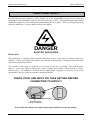
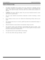
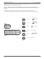
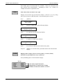
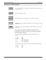
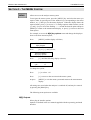
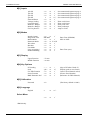
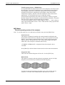
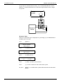
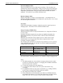
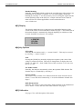
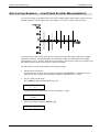
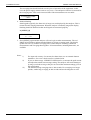
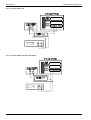
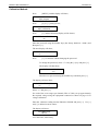
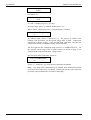
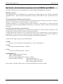
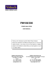
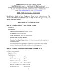
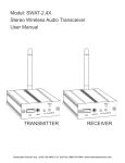
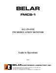
www.voltech.com PM100/300 POWER ANALYZERS USER MANUAL Thank you for choosing to use this Voltech Power Analyzer. Should you experience any difficulty during the set up or use of any Voltech product, or are unsure of any of their features or abilities, please do not hesitate to contact either your local supplier or one of our Voltech offices. Voltech Instruments Inc. 11637 Kelly Road, Suite 306 Fort Myers, FL 33908 U.S.A. Tel: 239 437 0494 Fax: 239 437 3841 [email protected] Voltech Instruments Ltd. 148 Harwell Int’l Business Centre, Abingdon. OX11 0RA U.K. Tel: +44 (0) 1235 834555 Fax: +44 (0) 1235 835016 [email protected] WARRANTY This product is warranted against defect in materials and workmanship for a period of one year from the date of shipment. During the warranty period, Voltech will, at its option, either repair or replace products which prove to be defective. For repair services under warranty, the instrument must be returned to a service centre designated by Voltech. Please contact your local supplier for details. Limitation of Warranty The foregoing warranty shall not apply to defects resulting from unauthorised modification or misuse, or operation outside specification of instrument. No other warranty is expressed or implied. Whilst every care has been taken in compiling the information in this publication Voltech cannot accept legal liability for any inaccuracies contained herein. Voltech has an intensive programme of design and development which may well alter product specification, and reserve the right to alter specification without notice and whenever necessary to ensure optimum performance from its product range. Because software is inherently complex and may not be completely free of errors, you are advised to verify your work. In no event will Voltech be liable for direct, indirect, special, incidental or consequential damages arising out of the use of or inability to use software or documentation, even if advised of the possibility of such damage. All rights reserved. No part of this publication may be produced, stored in a retrieval system, or transmitted in any form, or by means, electronic, mechanical photocopying, recording or otherwise without prior permission of Voltech. Copyright Voltech Instruments Ltd 1996-2004. Voltech Part Number 98-052 Issue 6. March 2004. PM100 / 300 USER MANUAL HEALTH AND SAFETY HEALTH AND SAFETY Electrical devices can constitute a safety hazard. It is the responsibility of the user to ensure the compliance of the installation with any local acts or bylaws in force. Only qualified personnel should install this equipment, after reading and understanding this users guide. These operating instructions should be adhered to. If in any doubt, consult your supplier. DANGER ELECTRIC SHOCK RISK Please note: This equipment is supplied under warranty conditions in force at the time of purchase from your supplier. Contact your supplier for details. Any attempt to disassemble or modify the unit will render any warranty agreement invalid. The contents of this guide are believed to be accurate at the time of printing. The manufacturers, however, reserve the right to change the content, product specification, and performance criteria, without notice. No liability is accepted for the inappropriate, negligent, or incorrect set-up of the instrument by the user, either by manual or automated means. CHECK YOUR LINE INPUT VOLTAGE SETTING BEFORE CONNECTING TO SUPPLY! 230 Read line input voltage setting here Pull out the fuse drawer and rotate the grey fuse holder to change the setting. VPN 98-052 i HEALTH AND SAFETY PM100 / 300 USER MANUAL SAFETY PRECAUTIONS 1. The PM100 and PM300 power analyzers have been constructed in compliance with the requirements of EN61010-1, Pollution Degree 2, Installation Category II, FOR INDOOR USE ONLY. This ensures the safety of the meter and the user when normal precautions are followed. 2. WARNING: The analyzer MUST be earthed. The power source should be inserted in a socket with a protective ground contact. 3. The power source should be inserted before connections are made to measuring or control circuits. 4. Do not attempt to remove outer cover without first disconnecting auxiliary and test power supply. 5. This instrument must only be serviced by qualified personnel who understand the danger of shock hazards. 6. When the instrument is removed from its case hazardous voltages are present. 7. The electronic circuitry of this instrument is fully floating with respect to ground. If the instrument is opened and dangerous voltages (above 50V peak) applied to the input terminals then all the circuitry must be considered 'Live'. 8. The signal leads must be in good condition with no damage. 9. Use a fuse only with the same type and rating - 315mAT ii VPN 98-052 PM100 / 300 USER MANUAL CONTENTS CONTENTS PAGES Section 1 Getting Started 1 Section 2 Function Keys 7 Section 3 The Menu System 9 Example: Low-Power Standby Measurements 19 Section 4 Calibration 21 Section 5 Specifications 25 Section 6 Accessories 29 Section 7 EMC Compliance 31 VPN 98-052 iii CONTENTS iv PM100 / 300 USER MANUAL VPN 98-052 PM100 / 300 USER MANUAL GETTING STARTED SECTION 1 - GETTING STARTED Thank you for purchasing a Voltech Power Analyzer. Your analyzer comes supplied with: 1. This Manual 2. A Power Lead 3. Safety Insulated test leads; PM100:- 2 yellow, 2 black PM300:- 6 yellow, 6 black 4. Safety crocodile clips 5. A Voltech product registration card Please report any missing items to your Voltech product supplier immediately. When you return your product registration card to Voltech, we will ensure that you continue to receive news of the latest applications software and hardware available for your power analyzer. PM100 and PM300 power analyzers are ideal for making accurate measurements on most electrical and electronic equipment. Measurements on pulsewidth-modulated motor drives present special problems however, and we recommend the use of special ‘PWM Mode’ on other Voltech analyzers for this application. All PM100 and PM300 power analyzers are supplied with a power lead, and the line voltage selector switch and menu language suitable for use in their intended destination country. Please check the line voltage setting on the IEC line socket at the back of the power analyzer. CHANGING THE LANGUAGE Press [MENU] SELECT MENU M[0] Outputs Press [6] or [>] until you see the following display; SELECT MENU M[6] Language Press [↵] x Press ENGLISH >√< [<] ENGLISH >x< √ Press [↵] to move to the next item in the menu system, or, press [MENU] to exit the menu system and return to the measurement display. The menu will now be displayed in the alternative language available in your power analyzer. VPN 98-052 PAGE 1 GETTING STARTED PM100 / 300 USER MANUAL ADJUSTING THE LCD DISPLAY CONTRAST Switch the analyzer ON. Before pressing any other keys, press and hold the [<] or [>] key to adjust the display contrast to suit your angle of view. The [<] key will darken the display, and the [>] will make it lighter. CONNECTING THE ANALYZER Connect the analyzer as shown below. Direct connection to the analyzer’s voltage and current inputs gives the best accuracy. For higher current applications that require current transformers or external shunts, see page 10. HI A LO HI V CH1 LO L LOAD L HI or V CH1 LO LOAD CH1 N N LO A Single-phase, Two wire and DC measurements HI CH1 HI A LO L V HI LO LOAD CH1 LOAD CH1 V CH2 LO HI Single-phase, Three wire* LOAD N L HI A LO CH2 Three Phase Source Ph1 HI A LO Ph1 CH1 Ph2 HI LO Ph2 A CH2 V CH1 or HI LO A LO Ph2 LO HI Ph2 A CH2 Ph3 HI A LO Ph3 V CH1 Ph1 HI LO V CH2 HI LO V CH3 A LO Ph2 CH2 Ph3 HI A CH3 N Three-phase, Three wire* (3 wattmeter method Set Analyzer to Three Phase, Four Wire mode) Ph1 A HI Three Phase Load or LO CH1 Ph2 or HI LO HI Three-phase, Three wire* (2 wattmeter method) Ph1 CH1 or or HI Ph3 CH3 Three Phase Source LO V CH2 Ph3 Ph1 Three Phase Source HI Three Phase Load LO Ph3 V CH1 HI LO V CH2 HI LO V CH3 Three Phase Load HI LO N Three-phase, Four wire* (3 wattmeter method) or *PM300 only. See page 13 for selection of wiring mode. PAGE 2 VPN 98-052 PM100 / 300 USER MANUAL GETTING STARTED With the analyzer connected, and with power applied, the default display shows Volts, Amps and Watts. On a PM300, quantities for 3 channels and sum are shown. The green LED on the front panel is illuminated when the analyzer has detected a stable fundamental frequency. Harmonic measurements are invalid when this LED is not lit (when measuring DC quantities for example). The third line of the display can be changed to show any of the 6 basic measurement functions: (The selected measurement mode will be indicated on the display, in the position marked with a * below.) * V V RMS = 1 T ARMS = 1 T ∫ T 0 v i2 dt True RMS Voltage PM100 113.0 V rms 0.524 A rms +0.000 * A True RMS Current W W = 1 T ∫ T 0 ∫ T 0 ii2 dt v i ii dt Real Power CH1 CH2 CH3 107.66 107.89 107.99 186.79 V rms 142.43 155.52 0.000 99.32 A rms +0.000 +0.000 +0.000 +0.000 * PM300 VA VA = VRMS ∗ ARMS Volt - Amperes VAr (VA) 2 − W 2 VAr = PF = W VA Volt - Amperes reactive PF True Power Factor VPN 98-052 PAGE 3 GETTING STARTED FREQ PM100 / 300 USER MANUAL Frequency The frequency of the input waveform is obtained using the [FREQ] key. The lowest of the frequencies detected on the Channel 1 V and A inputs is displayed. This frequency is used as the fundamental for harmonic analysis. FUND Fundamental value. V.f, A.f, W.f, VA.f, Var.f, PF.f The fundamental (1st Harmonic) component of the 6 basic measurements are quickly shown by using the [FUND] key. PF.f is the power factor due to the fundamental components of voltage and current. This is equivalent to cos∅ in a sinewave system. Cos∅ has a sign to denote leading or lagging current, and the convention used is shown below: 0°° -90°° -180°° -270°° -360°° W + - - + PF.f - - + + Var.f + + - - For Watts, + or - indicates the direction of the power flow. For PF.f, + indicates that I leads V (Capacitive). For Var.f + indicates an inductive load. The sign used to indicate fundamental power factor may be reversed in menu 4. For example; Press [MENU] SELECT MENU M[0] Outputs Press [4] or [>] until you see the following display; SELECT MENU M[4] Key Options Press [↵] PF LEADING >-< + Press [<] and [>] to make your selection PF LEADING >+< PAGE 4 Press [↵] to move to the next item in the menu system, or, press [MENU] to exit the menu system and return to the measurement display. VPN 98-052 PM100 / 300 USER MANUAL GETTING STARTED Four further types of measurement are available. These are associated with only specific basic measurements. Attempting to show ‘VA’ ‘PEAK’ for example will result in a parameter error. PEAK Peak value of the waveform V pk, A pk. Display of crest factor may be selected in menu 4. Select V cf, A cf by using the [V] and [A] keys in [PEAK] mode. Press [PEAK] again to cancel. Press [MENU] SELECT MENU M[0] Outputs Press [4] or [>] until you see the following display; SELECT MENU M[4] Key Options Press [↵] until you see the following display; PEAK >pk< cf Press [<] and [>] to make your selection pk HARM PEAK >cf< Press [↵] to move to the next item in the menu system, or, press [MENU] to exit the menu system and return to the measurement display. Displays either Voltage (Vhxx), Current (Ahxx), or Power (Whxx) harmonics by pressing the [V], [A], or [W] keys. Press [HARM] again to cancel harmonic display. PM100 AH01 2.47 -015.1°° VPN 98-052 AH03 0.526 -160.8°° 1st, 3rd current harmonic Amplitude of harmonics in Amps Phase of harmonic relative to VH01 PAGE 5 GETTING STARTED PM100 / 300 USER MANUAL PM300 CH1 96.88 121.13m -002.3 CH2 97.08 134.38m -120.6 CH3 Σ 97.78 168.44 V rms 128.47m 127.99m AH01 -242.4 ° Amplitude of harmonic in Amps Phase of harmonic Use the [<] and [>] keys to scroll through harmonics 0 (dc) to 50. Harmonic amplitude can be shown as absolute values by selecting ‘V/A/W’ in menu 2. (See page 12 for example.) THD Total Harmonic Distortion. V thd, A thd. The power analyzer automatically selects the most accurate method of calculation, depending on the level of THD. Press [A] or [V] to select A thd or V thd. Press [THD] again to cancel THD display. THD > 6% df = THD < 6% thd = (RMS ) − H 12 X 100% H1 2 H 2 2 + H 32 + H 4 2 + H 52 + .... X 100% H1 See also the options in [MENU] [2] for how to manually select the formula that is used and how to change the harmonic reference (the denominator in the equations above). INTG Displays Integrated values. Ah, Wh, VAh, VArh, PF (Average) and fundamentals are valid. The period of integration is set in menu 2. Pressing the [INTG] key starts integration, and displays any of the integrated values during integration. Pressing the [INTG] key again returns the display to normal mode, integration continues in the background until the time set in menu 2 is reached. The orange LED is lit when the integrator is running. Press and HOLD the [INTG] key to stop integration. PAGE 6 VPN 98-052 PM100 / 300 USER MANUAL FUNCTION KEYS SECTION 2 - FUNCTION KEYS PROG Press and HOLD this key to toggle between default (Red LED off) and stored settings (Red LED on). MENU Enter and exit the menu system. < Move through menus, select settings etc. Clear erroneous menu data. > ↵ When measuring: acts as a HOLD key (toggle). In the menu system: acts as the ENTER key. DISP PM300 only. Selects Channel on Display. Toggles display of Σ quantities and Neutral Amps. When in 1ph 2W mode, pressing the [DISP] key sequences through measurements on all 3 channels. In this mode, all 3 channels are operating independently of each other and are able to make measurements on different ranges and at different frequencies. For waveform display, the [DISP] key sequences through the following displays: 1/ 2/ 3/ 4/ 5/ 6/ V&A V&A V&A V A V&A CH1 CH2 CH3 CH1, CH2 and CH3 CH1, CH2 and CH3 CH1, CH2 and CH3 For barchart display, the [DISP] key sequences through the following displays: 1/ V & A 2/ V & A 3/ V & A VPN 98-052 CH1 CH2 CH3 PAGE 7 FUNCTION KEYS PAGE 8 PM100 / 300 USER MANUAL VPN 98-052 PM100 / 300 USER MANUAL THE MENU SYSTEM SECTION 3 - THE MENU SYSTEM MENU Allows access to the analyzer menu system. To navigate the menu system, press the [MENU] key and select the menu you require, either by pressing one of the number keys corresponding to the menu number, or [>] until you see the menu displayed. When the display shows the required menu, press [↵] to access it. To change options within a menu, use the [>] and [<] keys to move the flashing ‘> <‘ around the desired option and press [MENU] to return to the measurement display, or press [↵] to move to the next menu option. For example, to access the M[4] key options menu and change the display to show crest factor instead of peak; Press [MENU] and the display will show; SELECT MENU M[0] Outputs Press [4] or [>] until you see; SELECT MENU M[4] key options Press [↵] until the following display is shown; PEAK >pk< cf To change the option; Press [>] to select >cf< Press [↵] to move to the next item in the menu system, or press [MENU] to exit the menu system and return to the measurement display. All settings are stored when the analyzer is switched off, and may be restored by pressing the [PROG] key. The following menu options are available. M[0] Outputs Select plug-in interface options. Options are defined in the user manual supplied with the separately purchased interface. VPN 98-052 PAGE 9 THE MENU SYSTEM PM100 / 300 USER MANUAL M[1] Inputs or or or or or or or or or or ü ü ü >ü< ü ü ü ü ü ü 1ph 2W 1ph 3W 3ph 2W 3ph 4W External Shunt Voltage Scaling Current Scaling Manual V Range* Manual A Range* Fix Freq Source* >x< >x< >x< x >x< >x< >x< >x< >x< >x< Inrush Current Integration Time Ballast Mode Harmonic Mode Waveform Barchart Fast Mode Long Averaging* Disable Blanking >x< or ü HH:MM >x< or ü >%< or V/A/W >x< or ü >x< or ü >x< or ü >x< or ü >x< or ü Upper Function Middle Function >V rms< >A rms< See connection diagram on page 2 See connection diagram on page 2 See connection diagram on page 2 See connection diagram on page 2 Enter scale factor Enter scale factor Enter peak volts Enter peak amps Amps or Volts M[2] Modes Enter Time (HH:MM) 50Hz or 60Hz Enter Time (secs) M[3] Display M[4] Key Options PF Leading Peak Fix THD Formula Series Formula RMS Harmonic Ref >-< >pk< >x< >x< >x< or or or or or + cf ü ü ü (Sign of PF when I leads V) (Display peak or crest factor) (Auto or fixed formula select) (Choose fixed formula) (Reference for THD formula) M[5] Calibration Password >0< (The factory default is 3000) M[6] Language English x or >ü< >x< or ü Select Menu *PM100 only. PAGE 10 VPN 98-052 PM100 / 300 USER MANUAL THE MENU SYSTEM M[0] Outputs This menu is only available when a Voltech interface card is fitted. See page 23 for a full description of the cards available for your analyzer. For operating instructions, see the manual supplied with the interface card. M[1] Inputs The PM100 / 300 analyzers are highly versatile and can be configured to analyze almost any electrical system. The versatility is achieved because all power inputs are ac + dc coupled, and are isolated from each other and from the ground. The four main wiring modes are:[1ø2W] SINGLE PHASE, TWO WIRE. Select for single phase loads, two wire distribution system and rectifier output. [1ø3W] SINGLE PHASE, THREE WIRE. Select for three wire single phase distribution systems. [3ø3W] THREE PHASE, THREE WIRE. Select for three phase loads without neutral connection (two wattmeter method). Note that the [N] channel provides computed values of current (Arms, Afund, Acf, Apk, Aharm and Athd) for the third (unmeasured) phase of the system. [3ø4W] THREE PHASE, FOUR WIRE. Select for three phase loads with or without neutral connection (three wattmeter method). External Shunt For use with external shunts and other devices that produce a voltage proportional to the current being measured (E.g. some DC coupled current transformers.) The proportional voltage is applied between the ‘EXT’ and ‘LO’ terminals. Example: The scale factor is entered directly in mV/A. A twisted pair connection is recommended to minimize noise pick-up. VPN 98-052 PAGE 11 THE MENU SYSTEM PM100 / 300 USER MANUAL Voltage Scaling and Current Scaling For use with voltage transformers / dividers and current transformers. Connect to the V HI and LO terminals for voltage probes, and to the A HI and LO terminals for current probes. I = 10 Amp 100mV/A + EXT V = 1V LO 0.1 + A - - Current Scaling = 100mV/A Note: When using 1000:1 CT as in the above example, enter ‘1000’ as the current scaling. Manual Ranging. (PM100 Only) By default, the analyzers are fully auto-ranging. This is the ideal setting for most applications since the analyzers will then always be operating on the optimum range. No settings are required by the user in this case. In measurement applications where there are transients or bursts of signals, then data may be lost due to the time taken by the analyzer to perform the automatic range selection. In this case, the auto-ranging may be switched off and a manual range selected. The PM100 has 8 current and 8 voltage ranges as described below. To set a manual range, simply select ‘ü’ for Manual V Range or Manual A Range in M[2] and then enter the approximate maximum peak current or voltage that is expected. (This can be measured by pressing the PEAK key). It is not necessary to remember the exact ranges of the PM100, since they will be selected for you according to the following tables. Amps Peak Range 0.1 0.3A 0.9A 2.7A 8.1A 24.3A 72.9A 200A Amps Peak Entered 0.0 0.1 0.1 0.3 0.3 0.9 0.9 2.7 2.7 8.1 8.1 24.3 24.3 72.9 > 200 Volts Peak Range 7.5V 15V 30V 60 120V 240V 480V 1000V Volts Peak Entered 0.0 7.5 7.5 15 15 30 30 60 60 120 120 240 240 480 > 480 When a manual range is set, the analyzer will make accurate measurements for signals up to the specified range peak. Notes. 1) Small signals may not be displayed because of the analyzer’s display blanking feature and this should be disabled. See M[2] ‘Disable Blanking’. 2) Scaling is ignored. When setting a manual range, use the actual peak current or voltage seen at the terminals of the PM100. PAGE 12 VPN 98-052 PM100 / 300 USER MANUAL THE MENU SYSTEM Fixed Frequency Source (PM100 Only) It is important that the analyzer detects the correct frequency for analysis since this frequency is used in the calculation of rms and harmonic measurements. Good frequency detection is indicated by the green led on the front panel. Normally, the analyzers continuously scan both the voltage and current channels for frequency and this is the ideal method for most measurement applications. It is not usually necessary to adjust this setting. In measurement applications where there are transients or bursts of signals, then the analyzer may lose frequency synchronization momentarily. The green led will not be lit and the measurements may be unstable. To correct this problem, choose a fixed frequency source ‘ü’. If the voltage is always present and stable, choose ‘Volts’. If the current is always present and stable, choose ‘Amps’. M[2] Modes Special operating modes of the analyzer. Note: To exit the mode you are in and return to default set up, press the [PROG] key. Inrush Current The analyzer continuously monitors the current channels and displays the largest peak current observed. Only the [<] and [>] keys operate to reset the display. Auto-ranging is disabled in this mode, so the expected peak value must be entered. If in doubt, enter ‘200’ Amps when prompted, and then reduce this value to improve resolution and accuracy. ‘CURRENT OVERRANGE’ is displayed if the selected peak value is exceeded. Press [PROG] to deselect Inrush Current mode to make other measurements. Integration Time This is the time that the integrator will run for. See the [INTG] key. Ballast Mode The output of electronic and some ultrasonic equipment consists of a high frequency waveform heavily modulated at the line frequency. To make accurate measurements, the whole cycle at 50 or 60 Hz must be analyzed. To do this, select ‘Ballast Mode’ and choose 50 or 60 Hz. VPN 98-052 PAGE 13 THE MENU SYSTEM PM100 / 300 USER MANUAL To give the best measurement accuracy, it is recommended that the Voltech Ballast CT (current transformer) be used where high common mode voltages are present. PM100 PM300 HI A LO Electronic Ballast Tube Harmonic Mode Harmonic Amplitude may be displayed as a percentage (%) of fundamental or in RMS terms as desired. Press [MENU] SELECT MENU M[0] Outputs Press [>] until you see; SELECT MENU M[2] Modes Press [↵] until you see; HARMONIC MODE >%< V/A/W PAGE 14 Press [<] and [>] to make your selection. Press [↵] to move to the next item in the menu system, or, press [MENU] to exit the menu system and return to the measurement display. VPN 98-052 PM100 / 300 USER MANUAL THE MENU SYSTEM Waveform Display Mode This mode displays one cycle of the input waveforms. The waveforms are automatically scaled to fit the display, voltage on CH1 always being the larger. Since the waveforms are scaled for easy viewing, they should not be used for comparative measurements. The peak values of the waveform are shown alongside. This mode is not available in Ballast mode. Barchart Display Mode Displays bargraphs of voltage or current harmonics. All 50 harmonics are displayed, and individual detail can be displayed by pressing the [<] or [>] keys to scroll through the harmonics. Fast Mode In this mode the display averaging is reduced to provide a rapid response to changing inputs. This mode is not available in Ballast mode. Long Averaging (PM100 Only) This mode may be used to average measurements over a long interval from 10 to 300 seconds. Normally, the PM100 samples the waveforms at 200kHz and updates the display approximately every ½second. This is ideal for most measurement applications. When there are transient or burst signals, however, and it is the average measurements over a long period of time that are required, then ‘Long Averaging’ should be enabled. ‘ü’. The averaging time should be several times longer than the cycle of operation of the equipment under test. See also the ‘low-power standby measurements’ example later in this manual. Equipment Cycle Time < 1 second 1 < 10 sec 10< 60 sec > 60 sec Example Power supply in low power standby mode. Signs, message boards, oscillating fan. Soldering iron. Washing machine Long Averaging Time 10s 100s 300s 300s + Integrator. All measurements, including harmonics, are available in long averaging mode. Notes. 1) The display update rate varies with the averaging time used (10 to 3000 seconds). To indicate the analyzer is averaging, the red PROG led flashes whenever this mode is enabled. 2) To reset the averaging, press the PROG key. 3) To cancel this mode, return to the menu system and disable Long Averaging. 4) For equipment with very long cycles of operation (e.g. washing machine) use the long averaging mode and the integrator together. 5) The sample rate in this mode is 200kHz. 6) If this command is not documented in your RS232 or IEEE488 interface card manual, the format is :AVG:LNG nnn where nnn is an integer in the range 10 to 300. :CFG 1,0 may be used to return to normal mode. VPN 98-052 PAGE 15 THE MENU SYSTEM PM100 / 300 USER MANUAL Disable Blanking Normally, small signals which are below the specified range of the analyzer are not displayed. The display is 'blanked'. To view small signals, disable the blanking by selecting 'ü'. For best accuracy, however, bring the signals into the normal operating range of the analyzer. A simple external resistive shunt is often used for low current applications. See the technical note at www.voltech.com M[3] Display This display enables the user to change the top and middle functions of the screen to one of the six basic functions as shown on page 3. The bottom line of the numeric display is automatically changed depending on which one of the six basic functions are selected. For example: + 234.5 W 123.6VA 50.03 Hz M[4] Key Options PF Leading Normally the convention used is >+< means I leads V. This may be reversed by selecting >-< means I leads V. Peak Pressing the [PEAK] key normally displays the repetitive peak value of the voltage or current waveform. This may be changed here to display the Crest Factor, CF, where CF = Peak / RMS values of the waveform. For a sine wave the CF is 1.414. Fix THD Formula Normally, the analyzer automatically selects the optimum THD formula. The formula may be set manually by selecting 'ü'. Series Formula This menu is only available if 'Fix THD Formula' has been selected as above. Select 'ü' to use the series formula only, 'x' to use the difference formula. See Page 6. RMS Harmonic Ref Normally, the reference value used during THD calculation is the fundamental or H1. Select 'ü' to use the rms value as the reference. See page 6. M[5] Calibration See page 17 for a full description of this menu. PAGE 16 VPN 98-052 PM100 / 300 USER MANUAL THE MENU SYSTEM M[6] Language English or an alternative language may be selected for the menus. Select Menu By selecting >ü< at this menu, the screen will switch to the first menu option, [M0] Outputs and you may now scroll through all the menu options once again. If you wish to exit the menu system, select >x< at this menu and press [↵]. Alternatively, press the [MENU] key to return to the measurement display. VPN 98-052 PAGE 17 THE MENU SYSTEM PAGE 18 PM100 / 300 USER MANUAL VPN 98-052 PM100 / 300 USER MANUAL THE MENU SYSTEM APPLICATIONS EXAMPLE – LOW-POWER STANDBY MEASUREMENTS. An ac power supply is equipped with a low-power standby mode. In this mode, current is drawn from the supply in ‘bursts’ that occur every 300ms or so. The waveform is shown below. A measurement of the average input power is required to check the rating of the power supply. With default settings, the PM100 makes measurements at high speed and updates the display approximately every ½ second. With the waveform above, the measure ments are not stable, and the analyzer pauses while it auto-ranges in between readings. To make stable average measurements, follow this procedure. 1. Measure the peak current. In normal power on mode, press the [A] key and then the [PEAK] key. Amps peak will be displayed. In this example, the maximum reading was approximately –750mA. 2. Set up a fixed current range. Press [MENU], [1] and then [8 8 ] until you see: MANUAL A RANGE x >ü< and then enter the nominal peak current, ignoring the (-) sign: PEAK CURRENT >0.750< 3. Now set up long averaging in [MENU], [2]. LONG AVERAGING x >ü< VPN 98-052 PAGE 19 THE MENU SYSTEM PM100 / 300 USER MANUAL The averaging time should include several cycles of operation of the equipment. In this case, the power supply current seems to vary over a 2 second period. Choose 20 seconds for the averaging time. This can be increased later if the measurements are not stable. AVERAGING TIME >20.0< 4. Disable blanking. Small signals (typically less than 10% of range) are not displayed by the analyzer. This is normal for auto-ranging instruments. When the analyzer is manually ranged, the display blanking should be disabled so that small signals are measured properly. In [MENU] [2] DISABLE BLANKING x >ü< 5. Press [MENU] again and the analyzer will now begin to make measurements. The red PROG led will flash to indicate that the PM100 is in long averaging mode. The display update rate will vary with the averaging time, but the analyzer is making continuous measurements and averaging them together. All measurements, including harmonics, are available. Notes: i) ii) iii) PAGE 20 For improved accuracy for currents less than 10mA, use an external shunt or transducer. See www.voltech.com for a technical note. If you see the message ‘CURRENT OVERLOAD’, re-measure the peak current and adjust the manual current range setting. The analyzer will not be damaged by range overloads as long as they do not exceed the maximum ratings given in the specification. The maximum long averaging time is 300 seconds. For averaging over longer periods, enable long averaging at 300 seconds and use the integrator as well. VPN 98-052 PM100 / 300 USER MANUAL CALIBRATION SECTION 4 - CALIBRATION Calibration of your analyzer is valid for 12 month periods. If any input range is uncalibrated, the analyzer displays ‘CALIBRATION ERROR’ on power up. This may be bypassed by pressing the [↵] key. Equipment Required: High accuracy (0.02%) true RMS volt meter. 0-20A rms Current Generator, 120Hz 0-1000V rms Voltage Generator, 120Hz 1.000Ω precision shunt. (For < 2A rms) 0.1000Ω precision shunt. (For > 2A rms) Equipment Connections: IMPORTANT NOTE: For optimum performance, always calibrate with BOTH voltage and current present simultaneously. • During voltage calibration, apply approximately 100mA from the same ac source to the current channel. During current calibration (including external shunt), apply approximately 5V from the same ac source • to the voltage channel. For Voltage Calibration VPN 98-052 PAGE 21 CALIBRATION PM100 / 300 USER MANUAL For Current Calibration 1Ω<2A 0.1Ω>2A For Current Calibration (External Shunt) 1Ω PAGE 22 VPN 98-052 PM100 / 300 USER MANUAL CALIBRATION Calibration Method: Press [MENU] and the display will show; SELECT MENU M[0] Outputs Press [5] or [>] until you see; SELECT MENU M[5] calibration Press [↵] and the following display will be shown; ENTER PASSWORD >0< Enter the password using the number keys (the factory default is >3000<) and then press [↵]. The next display will show; CHANGE PASSWORD >x< √ Press [↵] to continue without changing the password. To change the password, select >√< using the [>] key and press [↵]. The display will then show; ENTER PASSWORD >0< Enter the new password using the number keys and then press [↵]. The display will now show; CALIBRATE VOLTS >x< √ Select >√< and press [↵] For each of the seven ranges per channel (VR1 to VR8), set up approximately the required voltage using the equipment connected as shown on page 15 for voltage calibration. Enter the voltmeter reading into the PM100 or PM300 and press [↵]. Use [>] and [<] to delete incorrect entries. The display will show; CALIBRATION BUSY for a short time, followed by VPN 98-052 PAGE 23 CALIBRATION PM100 / 300 USER MANUAL CALIBRATION PASS to continue, or; CALIBRATION FAIL If ‘FAIL’ is displayed, press [<] to retry. To skip a range, press [↵] when the display shows >0<. When ‘PASS’ is displayed, press [↵] and the display will show; CALIBRATE AMPS >x< √ To calibrate amps, select >√<and press [↵]. The process is similar to the calibrate volts procedure, for the current ranges AR1 to AR8. Connect the equipment as shown on page 15 for internal shunt calibration, and enter the current value which is voltmeter reading / shunt resistance. The next option in the calibration menu system is ‘CALIBRATE EXT’. For the external current ranges XR5 to XR8, connect as shown on page 16 for external shunt calibration and enter voltage values. The last menu in the calibration options is; SAVE CALIBRATION >x< √ Select >√<, and press [↵] to store the new calibration constraints. Note: Any stage of the calibration may be omitted. New calibration constants will only be used where they are entered. Entering [0] for any value causes the previously stored calibration to be used for that range. PAGE 24 VPN 98-052 PM100 / 300 USER MANUAL SPECIFICATION SECTION 5 - SPECIFICATION (AT 23OC ±5OC, 30 MINUTES WARM-UP.) Voltage Ranges (auto ranging) Accuracy Crest Factor Max input Input Impedance Effects of Common Mode Voltage 2Vrms to 1000V pk in 8 ranges : 7.5, 15, 30, 60, 120, 240, 480, 1000 Vpk 5Hz to 1kHz 1kHz to 50kHz* DC Continuous 1 sec 500Vrms 120Hz 100Vrms 10kHz Impedance to ground ±0.1% reading ±0.1% range ±10mV ±0.1% rdg ±0.1% rng ±10mV ±0.1%/kHz ±0.1% rdg ±0.1% rng ±10mV Up to 20 1000V pk 1500V pk >1MΩ in parallel with <10pF Less than 500mV Less than 1V Galvanic isolation. Capacitance approx. 100pF Current Ranges (auto ranging) Accuracy (excluding Neutral) Crest Factor Max input 20mArms to 20Arms in 8 ranges : 0.1, 0.3, 0.9, 2.7, 8.1, 24.3, 72.9, 200.0 Apk 5Hz to 1kHz 1kHz to 50kHz* DC Continuous 1 sec Input Impedance Effects of Common Mode Voltage EXT. SHUNT Range Equivalence Accuracy Max input Input Impedance Impedance to ground 500Vrms 120Hz 100Vrms 10kHz ±0.1% reading ±0.1% range ±1mA ±0.1% rdg ±0.1% rng ±1mA ±0.2%/kHz ±0.1% rdg ±0.1% rng ±2mA Up to 20 20Arms, 200Apk (16Arms when all three channels used on PM300) 60Arms 12.5mΩ on all ranges Less than 50mA Less than 50mA 12.5mVrms to 2.0Vpk 12.5mV/A 5Hz to 50kHz* Continuous ±0.1%rdg ±0.1%rng ±1mV ±0.2%/kHz 250Vrms 1MΩ on all ranges Galvanic isolation. Capacitance approx. 100pF *1kHz to 20kHz for the PM300 in three-phase, three-wire and three phase, four wire modes. VPN 98-052 PAGE 25 SPECIFICATION PM100 / 300 USER MANUAL Power Display Range 0 to 1,999GW Accuracy ±0.2% rdg ±0.2% rng ±5mW ±0.3%/kHz Apparent Power Display Range 0 to 1,999GVA Accuracy ±0.2% rdg ±0.2% rng ±5mVA ±0.3%/kHz Reactive Power Display Range 0 to 1,999GVAr Accuracy ±0.2% rdg ±0.2% rng ±5mVAr ±0.3%/kHz Power Factor Range 0.000 to ±1.000 Accuracy ±0.004 ±0.2% rdg ± 0.2% / kHz Crest Factor Range 1.000 to 19.999 (Ranges 2 to 8 only) Accuracy ± (% pk error + % rms error) Peak Voltage and Current Accuracy ±1%rdg ±1%rng ±0.2%/kHz (Ranges 2 to 8 only) Inrush Current Range 0-200A Accuracy ±3.0% rdg ±3.0% rng ±50mA Frequency Range 5Hz to 50kHz* Accuracy 0.2% rdg *1kHz to 20kHz for the PM300 in three-phase, three-wire and three-phase, four wire modes. PAGE 26 VPN 98-052 PM100 / 300 USER MANUAL SPECIFICATION Harmonics Range Bandwidth Accuracy 0 to 50 Fundamental 5Hz to 50kHz* Harmonics 10Hz to 250kHz Fundamental Volts ±0.1% rdg ±0.1% rng ±10mV ±0.1%/kHz Amps ±0.2% rdg ±0.1% rng ±1mA ±0.2%/kHz Harmonics ±(0.2 ± 0.1/kHz)% of fundamental THD Range 0% to 999% Accuracy ±0.4% rdg ± 0.1% / kHz Integrator Range 1min to 99hrs 59mins Environment Safety Operating 0 to +40oC Shipping -20 to +60oC Designed to comply with EN61010-1 Pollution Degree 2, Installation Category II Power Source 110V 90V to 132V 230V 195V to 265V Frequency 48Hz to 65Hz MAX. VA 25VA Fuse Type & Rating 315mAT Dielectric Strength Input - Case 4kV AC 50/60 Hz for 1 minute. Input - Power Srce 4kV AC 50/60 Hz for 1 minute Power Srce - Case 1.9kV DC for 1 minute *5Hz to 20kHz for the PM300 in three-phase, three-wire and three-phase, four wire modes. VPN 98-052 PAGE 27 SPECIFICATION PAGE 28 PM100 / 300 USER MANUAL VPN 98-052 PM100 / 300 USER MANUAL SPECIFICATION SECTION 6 - ACCESSORIES AVAILABLE FOR THE PM100 AND PM300 A number of interfaces have been designed for use with the PM100 and PM300 power analyzers: IEEE488.2 Interface. Full implementation of the IEEE488.2 bus communication standard using the latest National Instruments compatible circuits. Allows full control of the analyzer remotely. IEEE address may be any number from 2 to 30. Centronics (parallel) and RS232 (serial) Interface. The parallel connector (a 25 way D-type) connects to most printers with a Centronics type interface - matrix, jet and laser. User selected text is printed when the [↵] key is pressed. The RS232 connector (a 9 way D-type) may be used to connect to a serial printer, or to allow full remote control for the analyzer using the IEEE488.2 command set. The baud rate (1200 to 19200) is selected from the front panel. Chart Recorder and Alarm Contacts Interface. 12 measurements may be output onto a 15-way D-type for connection to a chart recorder or data logger. Each measurement is scaled for MAX and MIN level from the front panel. 2 isolated alarm relay contacts are also provided (rated 50V @1A) for plant control. The relays may be programmed (via the front panel) to operate when any measurement exceeds a preset MAX or MIN level. Extra integration features are provided for load shedding and peak demand applications. Voltech can also supply a range of current transformers: CT1000 Precision AC 0.2% dual ratio current transformer. 100A:1A and 1000A:1A. CL1000 AC clamp-on current transformer. 1000A:1A CL100 AC clamp-on current transformer. 100A:1A Lighting Ballast CT 5mA to 1A RMS current in two ranges. 5 kHz to 1MHz bandwidth. Maximum voltage (Ballast/Tube to output) - 1000vpk. Accuracy (20kHz to 500 kHz): - Amplitude better than 1% - Phase (current output) better than 1° - Phase (voltage output) better than 3° Please contact Voltech for details of the accessories and applications currently available. VPN 98-052 PAGE 29 SPECIFICATION PM100 / 300 USER MANUAL RACK MOUNTING DETAILS FOR THE PM100 AND PM300 IMPORTANT: Detail applies to PM100 / PM300 manufactured from late 2001 onwards. Earlier models have a case which is split along its sides and different drilling details apply. Request an issue 4 manual. Front Remove feet A A: 4 holes M3 thread Screw length: 10mm Max A BASE 174mm 164.6mm Drill rack tray with 4mm clearance holes. A A Assemble using M3x10mm pan head screws and washers. Do not overtighten. 59.8mm 189.2mm 34.1mm Two analyzers may be fitted side by side on one tray. Suitable shelves are 400mm deep Imrak 19” Cantilever shelves. Part Number : 802-562285B or similar PAGE 30 VPN 98-052 PM100 / 300 USER MANUAL EMC COMPLIANCE SECTION 7 - EMC COMPLIANCE DECLARATION OF CONFORMITY Manufacturer's Name Voltech Instruments Ltd Manufacturer's Address 65 Milton Park Abingdon, Oxon United Kingdom declares, that the product Product Name: Power Analyzer Model Number: PM100 conforms to the following Product Specifications Safety: BS EN 61010 (1993) EMC: BS EN 55022 (1995): Class A BS EN 50082-2 (1992) Supplementary Information: The product herewith complies with the requirements of the EMC Directives 89/336/EEC and 92/31/EEC and the Low Voltage Directive 73/23/EEC Signed for on behalf of Voltech Instruments Ltd Martin Whitley, Quality Manager Abingdon, United Kingdom June, 1996 VPN 98-052 PAGE 31 EMC COMPLIANCE PM100 / 300 USER MANUAL DECLARATION OF CONFORMITY Manufacturer's Name Voltech Instruments Ltd Manufacturer's Address 65 Milton Park Abingdon, Oxon United Kingdom declares, that the product Product Name: Power Analyzer Model Number: PM300 conforms to the following Product Specifications Safety: BS EN 61010 (1993) EMC: BS EN 55022 (1995): Class A BS EN 50082-2 (1992) Supplementary Information: The product herewith complies with the requirements of the EMC Directives 89/336/EEC and 92/31/EEC and the Low Voltage Directive 73/23/EEC Signed for on behalf of Voltech Instruments Ltd Martin Whitley, Quality Manager Abingdon, United Kingdom June, 1996 PAGE 32 VPN 98-052 PM100 / 300 USER MANUAL EMC COMPLIANCE EMC PRECAUTIONS Conducted and Radiated Emissions The PM100 and PM300 comply with the limits of BS EN 55022 Class A. To ensure continued compliance, the RS232 lead supplied for PC communications must be fitted with the ferrite at the analyzer end. Any other RS232 or Parallel Printer leads used should have a ferrite fitted at the end of the lead closest to the analyzer. Immunity The PM100 and the PM300 may be susceptible to Fast Electrical Transients on the power line and Electrostatic Discharges, which can disrupt the operation of the units. In the event of such an occurrence, to return the PM100 or PM300 to normal operation: 1) Switch off the power 2) Wait 5 seconds 3) Switch on again VPN 98-052 PAGE 33 EMC COMPLIANCE PAGE 34 PM100 / 300 USER MANUAL VPN 98-052