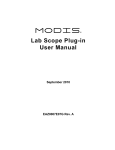
1
e-Flaps
FLAP CONTROLLER
INSTALLATION MANUAL
P/N 2071
SPECIFICATION IP-2071
REV. 2
Dec. 9, 2011
JDG
Approved
Aircraft Components Inc.
6539 Orchid Lake Rd
New Port Richey, FL. 34653
For Experimental Category Aircraft Only. Not FAA Approved
Flap Controller
I. INTRODUCTION
Welcome to the world of e-Flaps, the electronic Flap Controller. This
manual provides information for installing and operating the Flap Controller
on an experimental aircraft using a linear actuator to position the flaps. All
installation work should be performed in accordance with this manual and
the applicable sections of AC 43.13-1B.
II. SYSTEM DESCRIPTION
The Flap Controller is an electronic device that automatically positions the Electric Flaps in four
selectable positions: “Up”, “1”, “2” and “3”. Each position can be calibrated to stop the flaps at
a user determined flap angle.
Flap positions are selected by pressing four push-type green LED illuminating switches (switchlights) located on a 4” x 1.2” flap controller module that can be mounted vertically or
horizontally in any convenient instrument panel or console location. Flap position is indicated
by the steady illumination of one of the module switch-lights. This removes the requirement for a
separate flap position indicator but a RAC POS-12 or similar, position sensor must be installed
or the actuator must include this sensor internally.
The Flap Controller incorporates an interconnect to the optional P/N 2070 Gear Alert system
used on amphibian aircraft thereby eliminating the need to install a separate flap position cam
and micro switch.
Weighing only 3 oz, easy to read,
and fully automatic, the Flap
Controller removes the guesswork
and distraction of manually
positioning flaps during the busy
approach and departure phases of
flight.
Page 2 of 8
Flap Controller
III. SYSTEM OPERATION
When power is applied to a properly installed Flap Controller the system does a self test, each of
the four switch-lights illuminating briefly in sequence. If the self test is successful one switchlight will remain “ON” indicating the current flap position. In the unlikely event that the flaps are
in an intermediate position no switch light will illuminate. Pressing any switch-light will cause
the Flap Controller to move the flaps to the selected position. If the self test fails, switch-light
“2” and “3” will alternate “ON” and “OFF” indicating that the system has a broken wire or has
not been calibrated.
Warning: Do not use the Flap Controller until the system is calibrated. Failure to calibrate the
system could cause damage to actuators that do not have internal limit switches.
To select a flap position, briefly press the desired switch-light. The current flap position switchlight will extinguish. The selected switch-light flashes while the flaps are in motion and remains
ON STEADY once the flaps arrive at the new position. If desired, flaps can be moved several
positions at once. For example if the flaps are “UP” and position “3” is desired, briefly pressing
switch-light “3” will cause the flaps to transition directly from “UP” to position “3”.
If the position-sensing functions fails in flight it is possible to use the Flap Controller to
manually position the flaps.
a. First remove all power to the Flap Controller.
b. Now hold the “UP” switch-light depressed while reapplying power to the Flap
Controller. This will place the Flap Controller in Manual Mode.
c. While in Manual Mode, holding the “UP” switch-light will move the flaps “UP” and
holding “1” switch-light will move the flaps “DOWN”
In Manual Mode the Flap Controller does not indicate flap position. The flap actuator should
stop the flaps motion when the internal limit switches are reached (if installed). Intermediate
positions will have to be estimated by watching the flap movement.
IV. APPLICABILITY
This system is not FAA approved. It is intended for installation on Experimental category
aircraft only. The aircraft must meet the following minimum requirements for an installation.
a. 12 volt DC power.
b. Linear actuator rated no more than 5 amps and with fixed internal limit switches.
c. Linear actuator with internal position sensors or an external RAC POS-12 Position
Sensor or similar. The position sensor must have a resistance of 5 Kohm to 10 Kohm.
d. Tefzel wire sized and protected according to AC43.13-1B.
Page 3 of 8
Flap Controller
V. COMPONENT INSTALLATION AND WIRING
Basic Installation
NOTE – Do not have a battery charger hooked up while this unit is powered up as it may
damage some of the electronics. Unit should be run off battery power only.
a.
The Flap Controller can be mounted vertically or horizontally in the instrument panel or
any convenient consol that is within easy reach and sight of the pilot. The mounting
position must have sufficient space to allow for the depth of the Flap Controller module.
b.
This manual assumes that the aircraft has a linear flap actuator with fixed internal limit
switches and rated to a maximum of 5 amps under load. If actuator is rated more than 5
amps, 2 relays will have to be installed to control the actuator power (one for each line).
The flap actuator should be installed so that the internal limit switches will stop the flaps
at the zero-flap and full-flap positions. If actuator does not have internal limit switches, it
is recommended to install them.
c.
This manual assumes that the actuator has internal position sensor leads or the aircraft has
a RAC POS-12 Position Sensor (or similar) installed so that the sliding arm moves in
conjunction with the flaps and reaches full extension or is fully retracted with the flaps at
the actuator internal limit switch positions.
d.
Connect the RED wire to 12 volt DC aircraft power using Tefzel wire sized and protected
according to AC43.13-1B.
e.
Connect the BLACK wire to a convenient ground using appropriate Tefzel wire.
f.
Connect the VIOLET wire to the 2070 Gear Alert landing position sensor wire (as
installed). This connection will provide a ground whenever flaps are in position “2” or
greater.
g.
Using a bare-wire splice, temporarily connect the WHITE/BLACK wire to one of the flap
actuator power inputs with appropriately sized Tefzel wire.
h.
Using a bare-wire splice, temporarily connect the WHITE wire to the other flap actuator
power input with appropriately sized Tefzel wire.
i.
Using a bare-wire splice, temporarily connect the #22 AWG ORANGE (sensor voltage)
wire to the ORANGE/WHITE wire on the RAC POS-12 Position Sensor. The
j.
Using a bare-wire splice, temporarily connect the #22 AWG YELLOW (signal) wire to
the GREEN/WHITE wire on the RAC POS-12 Position Sensor.
k.
Using a bare-wire splice, temporarily connect the #22 AWG GREEN (sensor ground)
wire to the BLUE/WHITE wire on the RAC POS-12 Position Sensor.
Page 4 of 8
Flap Controller
Page 5 of 8
Flap Controller
Verifying Actuator Motion
a.
Insure that the Flap Controller is “OFF”. Place the Flap Controller in “Manual Mode”
by holding the “UP” switch-light depressed while applying power until the UP switchlight flashes.
b.
In Manual Mode pressing the “UP” switch-light should now move the flaps “UP” and
pressing the “1” switch-light should move the flaps “DOWN”.
c.
If pressing the “UP” and “1” switch-lights move the flaps in the wrong direction, reverse
the WHITE/BLACK and WHITE wire connections to the flap actuator.
d.
When the Flap Controller moves the flaps in the correct direction permanently connect
and insulate the WHITE/BLACK and WHITE wires.
Verifying Position Sensor Wiring
a.
Insure that the Flap Controller is in “Manual Mode”.
b.
Push the “UP” or “1” switch-lights to move the flaps to a mid position.
c.
Use a Digital Volt-Ohm Meter (DVOM) to measure the voltage at each of the sensor
temporary splice positions. The voltage at the Flap Controller YELLOW wire connection
should read approximately 2.4 volts. The voltage at the other two temporary splices
should read zero (ground) and slightly less than 5 volts. With the flaps in a mid position
the Flap Controller YELLOW wire must read a voltage greater than the GREEN wire
splice and less than the ORANGE wire splice. Reconnect the wires until the test voltages
are correct.
d.
Move the flaps towards the UP position and measure the voltage at the Flap Controller
YELLOW wire connection. The voltage should have increased from the previous 2.4 volt
reading. If the voltage is lower, swap the wires connected to the Flap Controller
ORANGE and GREEN wires.
e.
Permanently connect and insulate the YELLOW, ORANGE and GREEN wires.
f. Now move the flaps in the up direction until the internal limit switch shuts the actuator
off. Measure and record the voltage on the YELLOW wire. Move the flaps in the down
direction until the internal limit switch stops the actuator. Again measure and record the
voltage on the YELLOW wire.
Page 6 of 8
Flap Controller
VI. SYSTEM CALIBRATION
Note – For the system to function correctly, the actuator must be installed so that the flaps are
stopped by the Flap Controller, and not by the internal actuator limit switches.
a.
With the Flap Controller in Manual Mode move the flaps to the position that you want for
full UP. Measure the voltage on the YELLOW wire. It must be at least 0.05v less than the
full up internal limit switch shut-off position voltage recorded in (f) above. If it is not, it
will be necessary to adjust the flap position linkage to guarantee that the limit switch
activation point is beyond the desired full up position.
b.
While holding the “3” switch-light depressed, press and hold the “UP” switch-light until
the “UP” switch-light flashes once.
c.
With the Flap Controller in Manual Mode move the flaps to the first desired flap position.
d.
While holding the “3” switch-light depressed, press and hold the “1” switch-light until
the “1” switch-light flashes once.
e. With the Flap Controller in Manual Mode move the flaps to the second desired flap
position.
f.
While holding the “3” switch-light depressed, press and hold the “2” switch-light until
the “2” switch-light flashes once.
g.
With the Flap Controller in Manual Mode move the flaps to the final desired flap
position. Measure the voltage on the YELLOW wire. It must be at least 0.05v greater
than the full down internal limit switch shut-off position voltage recorded while verifying
position sensor wiring. If necessary select a higher position for full down or modify the
actuator installation.
h.
While holding the “2” switch-light depressed, press and hold the “3” switch-light until
the “3” switch-light flashes once.
i.
Remove and reapply power to the Flap Controller to place the system in Normal Mode.
The system will complete a self test indicated by each of the four switch-lights
illuminating briefly in sequence. If the self test is successful switch-light “3”will remain
“ON” indicating the current flap position (as calibrated in “h” above). Test each of the
switch-lights in turn to confirm the desired automatic flap movement and calibration of
the Flap Controller.
Verifying Gear Alert Wiring
a.
Refer to the Gear Alert Manual and check that the “Select Landing” interrogation occurs
at flap positions, “2”, “3” and while moving between these positions.
Page 7 of 8
Flap Controller
VII. FREQUENTLY ASKED QUESTIONS
(Not allocated)
VIII. DOCUMENTATION
a. The installer is responsible for making all logbook entries, revising weight and balance,
and other documentation as required.
b. System weight is 3 oz.
IX. MATERIALS
The following materials are included in the Flap Controller kit. Check all parts before beginning
the installation.
1 x Flap Controller module P/N 2071-1
1 x installation manual P/N IP-2071
Page 8 of 8