1
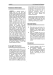
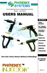
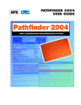
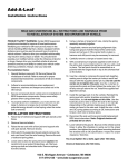
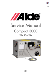
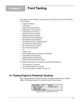
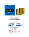
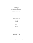
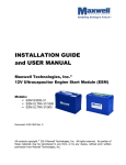
Mazda
Chapter 12
This chapter contains information for testing Mazda vehicles with the Asian Import Vehicle
Communication Software (VCS). The following Mazda systems may be available for testing:
•
•
•
•
•
•
•
Engine
Transmission
Antilock Brake System (ABS)
Airbag
Generic Electronic Module (GEM)
Instrument Cluster Module (ICM)
Transfer Case
12.1 Testing Engine and Transmission Systems
Mazda engine and transmission system testing includes:
• “Code Reading”
• “Manual Code Reading”
• “Functional Tests—All 1983–95 models except: 1991–94 Navajo; 1994 B-Series;
and 1994–95 626 2.0L ATX”
• “Functional Tests—All models with EEC-IV and EEC-V systems”
• “Transmission Code Retrieval—1987 626”
12.1.1 Code Reading
z
To read codes from vehicles with a 16-pin connector:
• Use the OBD-II adapter with the specified Personality Key™ device (Figure 12-1).
Figure 12-1 16-pin connector and OBD-II adapter with Personality Key™ device
123
Chapter 12
z
Testing Engine and Transmission Systems
To read engine and transmission codes from a 17-pin underhood connector:
• Connect the MAZDA-1 adapter to the 17-pin connector (Figure 12-2). For reading codes
manually, ground one of the following pins:
– TEN = Engine codes
– TAT = Transmission codes (most cars)
IMPORTANT:
Grounding the incorrect pin may result in vehicle damage.
FEN MEN
GND FAT FBS FAC
TAT TBS TAC
IGÐ GND
TEN B+
FSC
TSC
F/P
Figure 12-2 17-pin underhood connector and MAZDA-1 adapter
z
To read codes from vehicles with 6-pin and 1-pin connectors:
• Use the MULTI-2-B + 2E adapter (Figure 12-3).
2E
2B
Figure 12-3 6-pin and 1-pin connectors and MULTI-2 adapter
IMPORTANT:
When connecting to a vehicle with the above configuration, make sure the 1-pin connector is
properly identified. Failure to identify the right connector may result in scan tool damage.
i
NOTE:
Some vehicles retrieve transmission codes from the engine control module (ECM).
12.1.2 Manual Code Reading
Refer to Figure 12-4 for reading manual codes.
124
1.2 Sec.
On
Off
0.4 Sec.
1.6
Sec.
First Digit
(2)
4.0 Second
Code Separaton
Second Digit
(3)
Code 23
1
2
Code 12
Figure 12-4 Mazda engine, transmission, and ABS flash codes
12.1.3 Functional Tests—All 1983–95 models except: 1991–94
Navajo; 1994 B-Series; and 1994–95 626 2.0L ATX
i
NOTE:
Operations described in this section are not available on all tool platforms.
The following Functional Tests may be available for 1983–95 Mazda vehicles (Figure 12-5):
• OXYGEN SENSOR TEST—monitors the feedback signal from the exhaust gas oxygen
sensor (O2S).
• SWITCH TEST—checks certain switch circuits.
• BASE TIMING CHECK—commands the ECM to place the engine in the base timing
mode for ignition timing checks and adjustments.
FUNCTIONAL TEST MENU:
>OXYGEN SENSOR TEST
SWITCH TEST
BASE TIMING CHECK
Figure 12-5 Sample Mazda Functional Tests menu
z
To perform an oxygen sensor test:
1. From the Functional Tests menu, select OXYGEN SENSOR TEST.
A screen like Figure 12-6 displays.
MAKE SURE ENGINE IS RUNNING AND WARM
(IN CLOSED LOOP) BEFORE MONITORING THE
EXHAUST OXYGEN CONTENT.
PRESS Y TO CONTINUE
Figure 12-6 OXYGEN SENSOR TEST selected
2. Start and run the engine to warm it to normal operating temperature.
3. Press Y.
A screen like Figure 12-7 displays.
125
Chapter 12
Testing Engine and Transmission Systems
HOLD ENGINE AT 2000 RPM TO MONITOR
EXHAUST OXYGEN SENSOR.
........................................
EXHAUST_________LEAN
Figure 12-7 Oxygen Sensor Test
4. As instructed, accelerate the engine to 2000 RPM and hold it there.
LEAN and RICH indicate the condition of the exhaust. LED 3 flashes to indicate that the
scan tool is receiving a signal from the exhaust gas oxygen sensor.
z
To perform a switch test:
1. From the Functional Tests menu, select SWITCH TEST.
A screen like Figure 12-8 displays.
WITH KEY ON AND ENGINE OFF, TEST EACH
SWITCH. AS ANY SWITCH STATE CHANGES,
DISPLAY ALTERNATIVES HIGH/LOW & LED 3
GOES ON/OFF. PRESS Y TO CONTINUE.
Figure 12-8 SWITCH TEST selected
2. Press Y.
A screen like Figure 12-9 displays.
TEST ANY SW: NEUTRAL/CLUTCH INHIBITOR,
IDLE, HEADLAMP, BRAKE LAMP, BLOWER A/C,
REAR DEFROSTER, WATER THERMO.
SWITCH STATE___HIGH
Figure 12-9 Switch Test
i
NOTE:
Not all switches displayed apply to every vehicle. Refer to Mazda service procedures and
specifications for availability of specific switch tests.
As you test each switch, the SWITCH STATE parameter should alternately display HIGH
or LOW each time a switch status changes. Also, LED 4 turns on when this parameter
displays LOW, and off when HIGH. See Table 12-1 for individual switch test instructions.
Table 12-1 Individual switch test instructions (sheet 1 of 2)
SWITCH
126
TEST INSTRUCTIONS
Clutch
With the key on and engine off, SWITCH STATE alternates HIGH/LOW as the clutch
is depressed and released.
Neutral
SWITCH STATE alternates HIGH/LOW when switching from a drive state to a park/
neutral state.
Inhibitor
(A/T only) Make sure the engine is off. SWITCH STATE alternates HIGH/LOW as the
transmission is placed in gear and returned to neutral.
Idle
SWITCH STATE alternates HIGH/LOW as the accelerator pedal is pressed and
released.
Table 12-1 Individual switch test instructions (sheet 2 of 2)
SWITCH
TEST INSTRUCTIONS
Head lamp
SWITCH STATE alternates HIGH/LOW as the head lamps are turned on and off. Turn
off the head lamps after the test.
Brake Lamp
SWITCH STATE alternates HIGH/LOW as the brake pedal is pressed and released.
Blower
Turn the blower switch to the high position. SWITCH STATE alternates HIGH/LOW as
the blower switch position changes. Turn the blower off after the test.
A/C
With the blower set to low, SWITCH STATE alternates HIGH/LOW as the A/C is
turned on and off. Turn off the blower and air conditioner after the test.
Rear
Defroster
SWITCH STATE alternates HIGH/LOW as the rear defroster is turned on and off.
Turn off the rear defroster after the test.
Water
Thermo
SWITCH STATE alternates HIGH/LOW as the water thermo switch is disconnected.
Reconnect the switch after the test.
i
NOTE:
If coolant is at operating temperature, the LED is always on.
z
To perform a base timing check:
• From the Functional Tests menu, select BASE TIMING CHECK.
A screen like Figure 12-10 displays.
THE VEHICLE CHECK CONNECTOR HAS BEEN
GROUNDED BY THE SCANNER. BASE IGNITION
TIMING CAN NOW BE CHECKED.
PRESS N WHEN DONE.
Figure 12-10 Base Timing Check
i
NOTE:
On some models, the transmission test connector is under the instrument panel. Do not
connect to the engine test connector.
12.1.4 Functional Tests—All models with EEC-IV and EEC-V
systems
i
NOTE:
Operations described in this section are not available on all tool platforms.
Functional Tests are available for Mazda vehicles with EEC-IV and EEC-V control systems,
but menu items are completely different for each system. See “EEC-IV Functional Tests” on
page 128 and “EEC-V Functional Tests” on page 132 for details.
i
NOTE:
The ignition key should be switched off when selecting FUNCTIONAL TESTS from the MAIN
MENU - PCM on EEC-IV and EEC-V vehicles.
127
Chapter 12
Testing Engine and Transmission Systems
EEC-IV Functional Tests
i
NOTE:
Operations described in this section are not available on all tool platforms.
EEC-IV systems typically offer several functional tests (Figure 12-1).
The following EEC-IV functional tests are described:
•
•
•
•
•
“Computed Timing Test” on page 128
“Wiggle (Engine Off) Test” on page 128
“Wiggle (Engine Running) Test” on page 129
“Output State Check” on page 130
“Idle Speed Adjustment Test” on page 131
Computed Timing Test
This test checks ignition timing with the engine running at a controlled idle speed. It also
verifies the ability of the PCM to advance and retard timing. Connect either a timing light or a
magnetic timing meter to the engine before testing.
On most EEC-IV engines, the PCM advances timing 20° above the base timing setting. So if
the base timing specification is 10° BTDC, expect to read 30° BTDC with a timing light or
meter. Refer to Mazda service manuals for timing specifications and test procedures.
z
To conduct a computed timing test:
1. Select COMPUTED TIMING.
The “timing check” screen displays (Figure 12-2).
i
NOTE:
A “warning” message displays (Figure 12-3) if the timing check test is selected with the engine
running or with the ignition switch on. This means the PCM self-test output (STO) circuit is still
energized from a previous test. On some vehicles, this message can be ignored. If uncertain,
turn the key off, wait 10 seconds, restart the engine, then enter the test.
2. With the engine warm and running at idle, press Y to start the test.
3. Check the timing with a timing light or timing meter within 2 minutes.
Wiggle (Engine Off) Test
This test puts the EEC-IV system into a program that records intermittent service codes that
occur as you wiggle or tap on various engine sensors, actuators, and wiring connectors with
the ignition on and the engine off.
z
To conduct a wiggle (engine off) test:
1. Select WIGGLE (ENGINE OFF).
The test initiation screen displays (Figure 12-11).
128
*WIGGLE TEST - KEY ON, ENGINE OFF*
TURN KEY ON. DO NOT START ENGINE.
WITH KEY ON, PRESS Y TO CONTINUE.
........................................
Figure 12-11 Sample engine off wiggle test initiation screen
2. Switch the key on and press Y.
After a brief startup message, the test displays (Figure 12-12).
MOVE, WIGGLE, AND TAP THE HARNESS,
SENSORS, AND CONNECTORS. DO NOT TURN
KEY OFF DURING TEST! PRESS N TO EXIT
........................................
Figure 12-12 Sample engine off wiggle test screen
3. Wiggle or tap the engine sensors, actuators, and wiring connectors.
The bottom line of the screen is blank until a fault occurs and a code sets. If a code sets,
the bottom line displays a “memory code stored–run KOEO test” message. Always check
for memory DTCs after a wiggle test.
i
NOTE:
Do not wiggle the test adapter loose from the self-test connector during this test or a false
code may set. Always exit the test before turning off the ignition or a false code may result.
z
To read the service codes from a wiggle test:
• Select CODES MENU > KOEO SELF-TEST.
Wiggle (Engine Running) Test
This test places the EEC-IV system into a mode that records intermittent service codes as you
wiggle or tap on engine sensors, actuators, and wiring connectors with the engine running.
z
To conduct a wiggle (engine running) test:
1. Select WIGGLE (ENGINE RUNNING).
The test instruction screen displays (Figure 12-13).
*WIGGLE TEST - ENGINE RUNNING*
START ENGINE AND RUN AT IDLE. DO NOT
ACCELERATE. PRESS Y TO CONTINUE (OR
PRESS Y BEFORE STARTING ENGINE).
Figure 12-13 Sample engine running wiggle test instruction screen
2. If the engine is running, a warning message displays. Switch the engine off, wait
10 seconds, then restart the test. Otherwise, start and run the engine at idle speed.
3. Once the engine is fully warm, press Y to enter the test.
The screen momentarily displays a test initiated message (Figure 12-14), then switches
to the test screen (Figure 12-15).
129
Chapter 12
Testing Engine and Transmission Systems
TEST INITIATED ... PLEASE WAIT
TEST MAY TAKE 30 SECONDS TO START
IF TEST DOES NOT START, CYCLEKEY & RETRY
Figure 12-14 Sample engine running wiggle test initiated screen
MOVE, WIGGLE, AND TAP THE HARNESS,
SENSORS, AND CONNECTORS. DO NOT TURN
KEY OFF DURING TEST! PRESS N TO EXIT
........................................
Figure 12-15 Sample engine running wiggle test screen
4. Wiggle or tap on sensors, actuators, and wiring connectors.
The bottom line of the screen is blank until a fault occurs and a code sets. When a code
sets, the bottom line reads “memory code stored–run KOEO test,” but this message only
appears during a fault. Always check for memory DTCs after a wiggle test.
i
NOTE:
Do not wiggle the test adapter loose from the self-test connector during this test, or a false
code may set. Always exit the test before turning off the ignition.
z
To read the service codes from a wiggle test:
• Select CODES MENU > KOEO SELF-TEST.
Output State Check
This test allows you to switch the PCM signals to the engine actuators on and off to take
voltmeter readings. If the engine is running, turn it off before selecting the output state test.
i
NOTE:
The EEC-V OUTPUT STATE TEST is the same as the EEC-IV OUTPUT STATE CHECK, the
test name is the only difference; the function is the same.
z
To conduct an output state test:
1. Select OUTPUT STATE CHECK.
The test initiation screen displays (Figure 12-16).
*OUTPUT STATE TEST*
PRESS Y, THEN TURN KEY ON.
THE ENGINE.
DO NOT START
Figure 12-16 Sample output state test initiation screen
2. Press Y, then switch the ignition on without starting the engine.
130
IMPORTANT:
When the test begins, all actuators (except IAC and fuel injectors) should be off and the PCM
circuits from the should be high (above 10 V). Use the DVOM or lab scope to check actuators.
A “self-test initiated” screen displays, followed by the test screen (Figure 12-17).
TO TOGGLE ACTUATORS ON/OFF, SNAP THE
THROTTLE. CHECK THE ACTUATORS
INDIVIDUALLY WITH A DVOM.
** ACTUATORS OFF **
Figure 12-17 Sample output state test screen
3. Press the accelerator to wide open throttle (WOT) to switch all engine actuators from off
to on, or from on to off.
All of the actuators stay on or off until the throttle is pressed again. As the actuators
change state, the bottom line of the display shows if they are on or off.
Idle Speed Adjustment Test
This test allows you to adjust the idle speed for certain 1991 and later engines. Before
adjusting idle speed, make sure the throttle body and idle speed control (ISC) device are
clean, and the throttle linkage is not sticking or binding.
Also, switch all accessories off and make sure the O2S is working properly, ignition timing is
correct, and there are no vacuum leaks. Place the transmission in park or neutral before
selecting the test.
A command from the scan tool starts the engine-running test, and a signal from the EEC-IV
PCM indicates when the test is complete. During this waiting period, the cylinder identification
displays along with instructions to press the brake pedal, turn the steering wheel, or snap the
throttle. These actions are not necessary, however, doing them speeds the self-test.
IMPORTANT:
If any service codes other than “11–no faults present” are displayed after the engine-running
test, correct any code problems before proceeding with the idle adjustment.
z
To conduct an idle speed adjustment test:
1. Select IDLE SPEED ADJUST.
The test initiation screen displays (Figure 12-18). If another test was performed before
this one, a “warning” screen may display because the self-test output (STO) circuit is still
energized from the previous test. For some vehicles, it is safe to ignore this message and
enter the test. If you are uncertain, turn the key off, wait 10 seconds, and restart the
engine before entering the test.
*IDLE
START
FOR 2
PRESS
SPEED ADJUSTMENT*
ENGINE AND RUN AT 2000 RPM
MINUTES, OR UNTIL EGO IS WARM.
Y WHEN DONE.
[0:00]
Figure 12-18 Sample idle speed adjust test initiation screen
131
Chapter 12
Testing Engine and Transmission Systems
2. Start the engine and run at 2000 RPM for two minutes.
A timer displays in the lower right corner of the screen. Skip this warm-up if the engine is
already warm.
3. Press Y and the “test initiated” screen displays.
Once the test is complete, the scan tool sends a start-idle-test signal to the PCM. The
screen changes as the scan tool waits for a response from the PCM (Figure 12-19).
ENGINE RUNNING TEST COMPLETE. READY FOR
IDLE SPEED TEST. IF NO RESPONSE IN 15
SECONDS, IDLE TEST MAY NOT BE AVAILABLE
IN THIS EEC (SEE FORD REFERENCE MANUAL).
Figure 12-19 Sample idle speed adjust test complete screen
After the PCM response is received, the throttle stop screw adjustment screen displays
(Figure 12-20). The display indicates if idle speed is too high, too low, or correct. If the
display reads “TPS out of adjustment—fix first,” the throttle position sensor must be fixed
to proceed. If idle speed is correct, skip to the last step.
TURN THROTTLE STOP SCREW TO ADJUST RPM.
PRESS N WHEN DONE AND RPM IS IN SPEC.
CURRENT CONDITION IS:
** IDLE RPM________975
Figure 12-20 Sample idle speed adjust throttle stop screen
Ten minutes after the idle speed test signal is received, the PCM stops communicating.
Normally, this is enough time to complete the adjustment. If not, return to the Functional
Tests menu, select, and repeat the test.
4. Turn the throttle stop until “idle RPM correct” displays.
5. Press N when the idle RPM is correct.
An instruction and verification screen displays (Figure 12-21).
RUN ENGINE AT 1500 RPM FOR 10 SECONDS.
WHEN DONE, PRESS Y TO RECHECK BASE IDLE,
OR PRESS N TO EXIT.
[0:00]
Figure 12-21 Sample idle speed adjust verification screen
6. Run the engine at 1500 RPM for 10 seconds, return to idle, and press Y.
7. An idle RPM correct message should display. If not, repeat the idle speed adjustment.
8. When the idle is properly adjusted, press N to exit.
EEC-V Functional Tests
i
NOTE:
Operations described in this section are not available on all tool platforms.
The following EEC-V functional tests are described:
132
• “Output State Test” on page 133
• “Module Identification Test” on page 133
i
NOTE:
The ignition key should be switched off when selecting FUNCTIONAL TESTS from the MAIN
MENU - PCM on EEC-V vehicles.
Output State Test
This test lets you switch PCM signals to the engine actuators on and off for testing with a
DVOM or lab scope. The engine must be off before the test is selected.
During a test, actuators stay on or off until you switch them. Actuators default to their normal
state after 10 minutes, if the vehicle is started, or if the ignition switch cycles off and on.
IMPORTANT:
Make sure the fuel system is intact before proceeding. Selecting ALL OUTPUTS ON causes
the electric fuel pump to briefly energize. Also, make sure fan blades are clear of obstruction
before selecting low or high speed fan on.
z
To conduct an output state test:
1. Select OUTPUT STATE TEST.
A test activation screen displays.
2. Press Y and the test list displays (Figure 12-22).
>NORMALLY ON OUTPUTS OFF
ALL OUTPUTS ON
LOW FAN ON ONLY
HIGH FAN ON ONLY
Figure 12-22 Sample EEC-V output state tests
3. Select the desired test.
– If the vehicle performs the test, “activated” or “fan requested” displays to the right of
the selected test.
– If the vehicle does not perform the test, “error” displays to the right of the selected test.
– Take circuit readings while the test is activated.
Module Identification Test
This test displays the PCM software file, part number, and sometimes the vehicle VIN.
z
To conduct a module ID test:
1. Select MODULE ID TEST.
An identification screen displays (Figure 12-23). If a module does not store VIN
information, “not available” displays on the third line.
133
Chapter 12
Testing Engine and Transmission Systems
SOFTWARE FILE: CCAQAB3.HEX
MODULE PART #: F4WFBD
VIN: XXXXXXXXXXXXXXXX
Copyright Ford Motor Co. 1993
Figure 12-23 Sample EEC-V module identification screen
2. Press Y to print the screen, or press N to exit.
12.1.5 Transmission Code Retrieval—1987 626
Gathering codes from a 1987 626 transmission requires taking a reading from two wires on
the test connector. This can be performed with a dual trace graphing meter connected as
shown in Figure 12-24.
L/B (blue/black)
Y/B (yellow/black)
L/W (blue/white)
CH 2
CO
CH1
Ones Digit
Tens Digit
Figure 12-24 Connecting a Dual Trace Graphic Meter to a 1987 626 transmission connection
IMPORTANT:
Be aware that the negative meter lead is connected to a 12 V source on the Y/B (yellow/black)
wire; the transmission control module (TCM) grounds the other wires to create the signal.
Therefore, the displayed reading is inverted and the ones are the negative transitions.
This test may also be performed with a test lamp. Connect the ground lead of the test lamp to
the yellow/black wire and probe the other two wires of the test connector one at a time:
• The blue wire displays the tens digit of the code as a 0.4-second flash followed by a
2-second pause. The pattern then repeats. If there is no flash, no tens digit is present.
• The L/B (blue/black) wire displays the ones digit as either a 2.0-second flash, which is
counted as five, or a 0.4-second flash, which is counted as a one.
Combine the two readings, tens and ones, to get a two-digit code (Figure 12-25 on page 135).
134
Channel 1, Blue/Black Wire
0.4 Sec.
2.0 Sec.
Code Repeats
On
2.0 Sec.
Off
Count
as 5
Count Each
as 1
Ones Digit = 9
0.4 Sec.
Channel 2, Blue/White Wire
On
2.0
Sec.
Code
Repeats
Code
Repeats
Code
Repeats
Off
Tens Digit = 1
Code is 19 (Ones Digit + Tens Digit)
Figure 12-25 1987 626 transmission manual flash codes
12.2 Testing Antilock Brake Systems
When a ABS malfunction occurs, the ABS electronic control module (ECM) illuminates the
ABS lamp on the instrument panel. On some systems, the ABS ECM stores codes for most
malfunctions, and provides data stream information for some models. Codes transmit to a
scan tool through either the OBD-II diagnostic link connector (DLC) or the ABS test connector.
Data stream information displays when the ABS control system provides it.
i
NOTE:
The following sections apply to ABS systems on vehicles with or without traction control.
z
To read ABS codes from vehicles with a 17-pin underhood connector:
• Connect the MAZDA-1 adapter to the 17-pin connector (Figure 12-26). For reading codes
manually, ground the TBS pin.
IMPORTANT:
Grounding the incorrect pin may result in vehicle damage.
135
Chapter 12
Testing Antilock Brake Systems
FEN MEN
TEN B+
GND FAT FBS FAC
FSC
TAT TBS TAC
TSC
IGÐ GND
F/P
Figure 12-26 17-pin underhood connector and MAZDA-1 adapter
z
To read 1988–92 626/MX6 ABS codes:
• Connect an analog voltmeter to FBS (G/R) (Figure 12-27).
• Read malfunction code(s) by observing meter needle swings.
B
A
C
D
Figure 12-27 Analog voltmeter and terminal on 1988-1992 626/MX6
A—FBS (Green/Red)
B—TBS (Green Black)
C—GND (Black)
D—Jump wire
z
To read 1993–94 Navajo 4-Wheel Antilock (4WAL) brakes codes:
1. With the key off, jump the white, light blue, and black wires (Figure 12-28).
2. Turn the key on and remove the jumper within 5 seconds.
3. Count flashes. Code 16 is a system pass.
B
C
A
D
Figure 12-28 1993–94 Navajo with 4WAL
A—Black/Light Blue
B—Dark Green
C—Black
D—White/Light Blue
136
z
To read 1990–93 B-Series and MPV ABS codes:
1. Attach a jumper wire to Terminal C (yellow wire, Figure 12-29).
Ground the jumper wire to the chassis for one second and release it.
C
Figure 12-29 Terminal C on 1990–93 B-Series and MPV
2. Count flashes.
A flashing pattern consists of a number of short flashes and ends with a long flash. Count
flashes and include the long flash in the count.
IMPORTANT:
Always use a fused jumper wire when connecting to ground.
12.2.1 ABS Main Menu
After selecting ABS from the System Selection menu, the MAIN MENU - ABS displays
(Figure 12-30). Selections vary by model and year.
MAIN MENU (ABS)
>CODES MENU
DATA DISPLAY
MOVIES
CUSTOM SETUP
Figure 12-30 Sample Mazda MAIN MENU—ABS
The following main menu selections are discussed:
• “Service Codes” on page 137
• “ABS Data Communication Guidelines” on page 141
Refer to the user’s manual for your diagnostic tool for information on other menu options.
Service Codes
During a KOEO self-test, the ABS ECM transmits on-demand codes. On most systems,
continuous codes are gathered by selecting MEMORY CODES from the SERVICE CODE
MENU. Some systems gather continuous codes automatically after the KOEO self-test.
Select SERVICE CODES and the SERVICE CODE MENU displays (Figure 12-31):
• KOEO SELF-TEST—displays on-demand codes present with the ignition on, but the
engine not running. These are usually electrical open and short circuits and must be
137
Chapter 12
Testing Antilock Brake Systems
serviced first, before any continuous codes. On some systems, the KOEO test displays
continuous codes and the MEMORY CODES selection does not appear on the menu.
• MEMORY CODES—displays continuous codes of intermittent faults from the ABS
module, when available. Memory codes should be serviced last.
•
•
•
•
CLEAR CODES—clears continuous memory codes from the ABS ECM memory.
HOW TO GET CODES—displays how to manually gather and clear RABS codes.
REVIEW CODES—lets you view codes.
PRINT CODES—lets you print codes.
CODE MENU
>KOEO SELF-TEST
MEMORY CODES
CLEAR CODES
REVIEW CODES
PRINT CODES
Figure 12-31 Sample Mazda ABS SERVICE CODE MENU
Any time a self-test is selected, a self-test initiated message displays (Figure 12-32). This
message means the scan tool attempted to start the test, it does not mean the vehicle
responded. If the message stays on the screen more than a few minutes, the test probably did
not start. Should this happen, exit the test, cycle the ignition key, then retest.
SELF-TEST INITIATED...WAIT FOR CODES
TEST MAY TAKE 60 SECONDS TO START
IF TEST DOES NOT START,CYCLE KEY & RETRY
Figure 12-32 Sample KOEO self-test initiated
KOEO Self-Test
This selection initiates a self-test for ABS that is similar to that for the engine.
z
To conduct a KOEO self-test:
1. Select KOEO SELF-TEST.
A “key on” verification screen displays.
2. Make sure the ignition is switched on, then press Y.
The self-test initiated screen displays.
i
NOTE:
Some systems require the ignition to be cycled on after pressing the Y button. Follow
on-screen screen instructions.
3. At the end of the test, the service code list displays (Figure 12-33).
ENGINE RUNNING SELF-TESTSTART ENGINE
AT RUN AND IDLE. DO NOTACCELERATE.
PRESS Y TO CONTINUE (ORPRESS Y BEFORE
STARTING ENGINE).
Figure 12-33 Sample ABS service code list
138
If no codes are detected during the test a “P0000 no faults present” message displays.
Memory Codes
This selection displays the continuous codes of intermittent faults from the ABS ECM. Some
models automatically gather memory codes at the end of the KOEO self-test. Continuous
codes should be serviced last.
z
To gather memory codes:
1. Select MEMORY CODES.
A “key on” verification screen displays. Make sure the ignition is switched on.
2. Press Y to continue.
The self-test initiated screen displays.
When the ABS ECM finishes the test, the service code list displays. If no codes are
detected during the test a “P0000 no faults present” message displays (Figure 12-34).
SERVICE CODES
** CONTINUOUS MEMORY CODES-FIX LAST **
P0000 NO CODES PRESENT
** END OF LIST **
Figure 12-34 Sample ABS memory code list
Clear Codes
This selection erases any continuous codes from the ABS ECM memory.
On some systems, the KOEO test repeats and the scan tool then interrupts the self-test input
to clear memory. Some systems require the vehicle to be driven above 25 mph to clear codes.
Note the following when clearing codes:
• Some systems prioritize DTCs. After repairing and clearing a DTC, always recheck for
additional faults that may be present.
• Only continuous codes can be cleared. Codes from a KOEO self-test are on-demand
codes that must be serviced. Certain codes, such as those for the wheel speed sensors
and the pump motor, only set while the vehicle is being driven.
z
To clear the codes:
1. Select CLEAR CODES.
A “key on” verification screen displays. Make sure the ignition is switched on.
2. Press Y to continue.
The self-test initiated screen displays (Figure 12-35).
SELF-TEST INITIATED
WAIT FOR CODE CLEARING
Figure 12-35 Sample code clearing in progress screen
139
Chapter 12
Testing Antilock Brake Systems
3. When the test finishes a codes cleared screen displays (Figure 12-36).
CODES CLEARED
PRESS N TO EXIT.
Figure 12-36 Sample ABS codes cleared message
Clearing Code Memory
The scan tool retains codes in its memory. The scan tool memory, not vehicle memory, can
be cleared using any of the following methods:
• Repeat the test, which overwrites the previous code.
• Select a different system for testing.
• Enter a new vehicle ID.
Review Codes
Return to the service code menu from the KOEO self-test or memory code test and REVIEW
CODES displays as a selection (Figure 12-37).
SERVICE CODE MENU
>KOEO SELF-TEST
REVIEW CODES
MEMORY CODES
CLEAR CODES
PRINT CODES
Figure 12-37 Review codes available on the menu
When this selection is available, it indicates recorded codes are in scan tool memory from
either, or both tests.
z
To review codes:
1. Select REVIEW CODES.
A code list, similar to the lists displayed at the end of the self-tests, displays.
2. Fix the problems in the order listed. Also, remember these important points about the
review codes list:
– Review all codes until “end of list” appears.
– The scan tool saves codes from the most recent test for display under review codes.
On a re-test, codes from the previous test are replaced with a new list.
– Always write down continuous memory codes after any test.
– If MEMORY CODES was selected, the scan tool saves the codes in memory, but the
CLEAR CODES selection must be used to clear the ABS module memory.
Print Codes
This selection is available on the SERVICE CODE menu following either a KOEO self-test or
a memory code test. All printouts of the code list include the vehicle ID.
140
z
To print the service code list from memory:
1. Connect the scan tool to a compatible printer.
2. Select PRINT CODES.
ABS Data Communication Guidelines
i
NOTE:
ABS functions are disabled during data communication. If the vehicle is driven, ABS will not
function. The ABS lamp may flash rapidly during data transmission.
Follow these steps to enter and exit ABS data:
1. Verify that the ignition is off when entering the vehicle ID.
2. Turn the ignition on.
3. Select DATA DISPLAY.
4. Turn the ignition off after completing ABS data tests.
12.3 Testing Airbag, GEM, ICM & Transfer Case Systems
through the 16 Pin Connector
For 1996–2004 626 and B-Series models, you can select AIRBAG, GEM, ICM, or
TRANSFERCASE from the System Selection menu to open the MAIN MENU for the specified
system (Figure 12-38).
MAIN MENU (AIRBAG)
>CODES MENU
DATA DISPLAY
MOVIES
CUSTOM SETUP
Figure 12-38 Sample Airbag testing Main Menu
When the ECM sets a code, it continuously flashes the SRS warning lamp. The DTCs and
data stream information are available through the OBD-II diagnostic link connector (DLC).
The CODES MENU selection from the MAIN MENU for the specific system offers the choices
shown in Figure 12-39.
SERVICE CODE MENU
>KOEO SELF-TEST
MEMORY CODES
LAMP FAULT CODES
CLEAR CODES
Figure 12-39 Sample Airbag Service Code menu
The DATA DISPLAY selection is available on most 1996 and later vehicles. It operates
similarly to Data (No Codes) for engine testing.
141
Chapter 12
142
Testing Airbag, GEM, ICM & Transfer Case Systems through the 16 Pin Connector