1
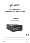
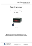
User manual for - METER WW-30
!
- Do not use the unit in areas where there is risk of explosions.
- Do not use the unit in areas with significant temperature variations, exposure to
condensation or ice.
- Do not use the unit in areas exposed to direct sunlight.
- Make sure that the ambient temperature (e.g. inside the control box) does not
exceed the recommended values. In such cases forced cooling of the unit must
be considered (e.g. by using a ventilator).
!
The unit is designed for operation in an industrial environment and must
not be used in a household environment or similar.
2. GENERAL CHARACTERISTICS
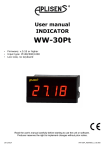
The WW-30 is a simple digital panel indicator, equipped with two measurement inputs.
One current input (0-20/4-20mA) and one voltage input (0-5/1-5/0-10/2-10V). Current input has
additionally overcurrent protection circuit, which protects standard resistor.
The selection of active input is realised by software, and selected input can be changed
at any time. Additionally the WW-30 allows user to select a conversion characteristic of several
kinds: linear, square, square root, and user defined (max.20 points length). Result is showed
on 4-digit LED display. Displayed values range can be selected by user, from -999 to 9999,
plus decimal point. Device WW-30 is equipped with RS-485 / Modbus RTU communication
interface .
The measurement range, active input and other parameters can be selected while
ordering. The device can be configured via IR remote controller or, optionally by PC via
RS-485 interface, or using simple RS-232 to IR converter. Moreover communication interface
RS-485 enables data transmission in any monitoring system equipped witch Modbus RTU
protocol.
Easy assembling, small dimensions, precision and reliability are the basic trumps of WW-30
indicators.
IR remote controller is not a part of the WW-30 and must be ordered separately.
3. TECHNICAL DATA
Power supply voltage
(depending on version)
External fuse (required)
Power consumption
230V AC ±10%; 50 ÷ 60 Hz (separated)
or 110V AC ± 10%, 50 ÷ 60 Hz (separated)
or 10...24...30V DC (not separated)
T - type, max. 2 A
max. 1,5 VA @ 230V AC and @ 110V AC
max. 1 W @ 24V DC
Current input
0÷20 mA, 4÷20 mA overload protected,
maximum input current about 50 mA
Current measurement accuracy
± 0,1% @ 25°C; ± one digit (for 0÷20 mA range)
Current input resistance
~ 50 Ω
4