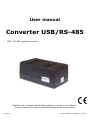
1
User manual
Converter USB/RS-485
•
USB / RS-485 signals convertion
Read the user's manual carefully before starting to use the unit or software.
Producer reserves the right to implement changes without prior notice.
2013.02.28
Converter USB/RS-485_INSHAEN_v.1.08.000
User manual - Converter USB/RS-485
CONTENTS
1. BASIC REQUIREMENTS AND USER SAFETY........................................................................................3
2. GENERAL CHARACTERISTICS................................................................................................................4
3. TECHNICAL DATA......................................................................................................................................4
4. DEVICE INSTALLATION............................................................................................................................5
4.1. UNPACKING.......................................................................................................................................5
4.2. CONNECTION METHOD...................................................................................................................5
4.3. MAINTENANCE..................................................................................................................................8
5. PREPARATION OF THE UNIT TO WORK ...............................................................................................9
5.1. INSTALLATION OF DEVICE DRIVERS............................................................................................9
5.2. SERIAL PORT CONFIGURATION..................................................................................................11
5.3. REMOVING OF DEVICE DRIVERS................................................................................................12
6. EXAMPLE OF THE RS-485 NETWORK CONNECTION ........................................................................13
Explanation of symbols used in the manual:
!
- This symbol denotes especially important guidelines concerning the installation and
operation of the device. Not complying with the guidelines denoted by this symbol
may cause an accident, damage or equipment destruction.
IF THE DEVICE IS NOT USED ACCORDING TO THE MANUAL THE USER IS
RESPONSIBLE FOR POSSIBLE DAMAGES.
i
2
- This symbol denotes especially important characteristics of the unit.
Read any information regarding this symbol carefully
User manual - Converter USB/RS-485
1. BASIC REQUIREMENTS AND USER SAFETY
!
- The manufacturer is not responsible for any damages caused by
inappropriate installation, not maintaining the proper environmental
conditions and using the unit contrary to its assignment.
- Installation should be conducted by qualified personnel . During installation all
available safety requirements should be considered. The fitter is responsible for
executing the installation according to this manual, local safety and EMC
regulations.
- The unit must be properly set-up, according to the application. Incorrect
configuration can cause defective operation, which can lead to unit damage or
an accident.
- If in the case of a unit malfunction there is a risk of a serious threat to the
safety of people or property additional, independent systems and
solutions to prevent such a threat must be used.
- Neighbouring and connected equipment must meet the appropriate standards
and regulations concerning safety and be equipped with adequate overvoltage
and interference filters.
- Do not attempt to disassemble, repair or modify the unit yourself. The unit
has no user serviceable parts. Defective units must be disconnected and
submitted for repairs at an authorized service centre.
!
- In order to minimize fire or electric shock hazard, the unit must be protected
against atmospheric precipitation and excessive humidity.
- Do not use the unit in areas threatened with excessive shocks, vibrations, dust,
humidity, corrosive gasses and oils.
- Do not use the unit in areas where there is risk of explosions.
- Do not use the unit in areas with significant temperature variations, exposure to
condensation or ice.
- Do not use the unit in areas exposed to direct sunlight.
- Make sure that the ambient temperature (e.g. inside the control box) does not
exceed the recommended values. In such cases forced cooling of the unit must
be considered (e.g. by using a ventilator).
!
The unit is designed for operation in an industrial environment and must
not be used in a household environment or similar.
3
User manual - Converter USB/RS-485
2. GENERAL CHARACTERISTICS
The Converter USB/RS-485 module is designed to connect a USB host to slave devices
equipped with RS-485 interface. The PC with special software can be used as a host. The
Converter USB/RS-485 unit guarantees full galvanic isolation between USB and RS-485
circuits. Warning - only one Converter USB/RS-485 can be connected to RS-485 line.
The converter can work with any devices equipped with RS-485 interface. The module
contains FT232BM integrated circuit produced by FTDI Chip company, and it supports USB
1.1 and USB 2.0 standards.
The main purpose of Converter USB/RS-485 is connection of PC host computer with
industrial data acquisition and visualisation systems based on RS-485 interface.
3. TECHNICAL DATA
Power supply voltage
Supply current
From USB interface (4,4V - 5,25V DC)
max. 150 mA
Galvanic separation
between RS-485 line and USB interface.
USB connector
1x USB B type, USB type A-B cable (length about 1,5 m)
is delivered with the unit.
Baud rate
300 bit/s - 115200 bit/s
Housing dimensions
Weight
40 x 55 x 100 mm
170 g
Operating temperature
(depending on version)
0°C to +50°C
or -20°C to +50°C
Storage temperature
(depending on version)
-10°C to +70°C
or -20°C to +70°C
Humidity
Altitude
5 to 90% no condensation
up to 2000 meters above sea level
Screws tightening max. torque
Max. connection leads diameter
EMC
0,5 Nm
2,5 mm2
PN-EN 61326-1
Supported systems
Windows 98/ ME/ 2000/ XP/ Vista / 7
!
4
This is a class A unit. In housing or a similar area it can cause radio
frequency interference. In such cases the user can be requested to use
appropriate preventive measures.
User manual - Converter USB/RS-485
4. DEVICE INSTALLATION
The unit has been designed and manufactured in a way assuring a high level of user
safety and resistance to interference occurring in a typical industrial environment. In order to
take full advantage of these characteristics installation of the unit must be conducted correctly
and according to the local regulations.
!
- Read the basic safety requirements on page 3 prior to starting the installation.
- All installation works must be conducted with a disconnected power supply.
- Protecting the power supply clamps against unauthorized persons must be
taken into consideration.
4.1. UNPACKING
After removing the unit from the protective packaging, check for transportation damage.
Any transportation damage must be immediately reported to the carrier. Also, write down the
unit serial number on the housing and report the damage to the manufacturer.
Attached with the unit please find:
- user’s manual for Converter USB/RS-485 device
4.2. CONNECTION METHOD
Caution
!
- Installation should be conducted by qualified personnel . During installation all
available safety requirements should be considered. The fitter is responsible for
executing the installation according to this manual, local safety and EMC
regulations.
- Wiring must meet appropriate standards and local regulations and laws.
- In order to secure against accidental short circuit the connection cables must be
terminated with appropriate insulated cable tips.
- Tighten the clamping screws. The recommended tightening torque is 0.5 Nm.
Loose screws can cause fire or defective operation. Over tightening can lead to
damaging the connections inside the units and breaking the thread.
- In the case of the unit being fitted with separable clamps they should be inserted
into appropriate connectors in the unit, even if they are not used for any
connections.
- Unused clamps (marked as n.c.) must not be used for connecting any connecting
cables (e.g. as bridges), because this can cause damage to the equipment or
electric shock.
5
User manual - Converter USB/RS-485
Due to possible significant interference in industrial installations appropriate measures
assuring correct operation of the unit must be applied. To avoid the unit of improper
indications keep recommendations listed below.
-
Avoid common (parallel) leading of signal cables and transmission cables together with
power supply cables and cables controlling induction loads (e.g. contactors). Such cables
should cross at a right angle.
Contactor coils and induction loads should be equipped with anti-interference protection
systems, e.g. RC-type.
Use of screened signal cables is recommended. Signal cable screens should be
connected to the earthing only at one of the ends of the screened cable.
In the case of magnetically induced interference the use of twisted couples of signal
cables (so-called “spirals”) is recommended. The spiral (best if shielded) must be used
with RS-485 serial transmission connections.
In the case of interference from the power supply side the use of appropriate antiinterference filters is recommended. Bear in mind that the connection between the filter
and the unit should be as short as possible and the metal housing of the filter must be
connected to the earthing with largest possible surface. The cables connected to the filter
output must not run in parallel with cables with interference (e.g. circuits controlling relays
or contactors).
max. 2 mm
Connections are made using the screw connections on the back of the unit’s housing.
The connections should be made accordingly to sticker on the top of converter's housing.
(Figure 4.1 - 4.2).
6-7 mm
Figure 4.1. Method of cable insulation replacing and cable terminals
6
User manual - Converter USB/RS-485
LEDs functions:
LED ON (yellow)
- signalises that unit is connected to the host, powered, and the USB
drivers installed
LED TX (red)
- signalises that unit is sending data to RS-485 line
LED RX (green)
- signalises that unit is receiving data from RS-485 line
host USB
RX
TX
ON
1 2 3 4
n.c.
A+
B- GND
Figure 4.2 Connection method
4.3. MAINTENANCE
The unit does not have any internal replaceable or adjustable components available to
the user. Pay attention to the ambient temperature in the room where the unit is operating.
Excessively high temperatures cause faster ageing of the internal components and shorten the
fault-free time of unit operation.
In cases where the unit gets dirty do not clean with solvents. For cleaning use warm water with
small amount of detergent or in the case of more significant contamination ethyl or isopropyl
alcohol.
Using any other agents can cause permanent damage to the housing.
Product marked with this symbol should not be placed in municipal waste. Please
check local regulations for disposal and electronic products.
7
User manual - Converter USB/RS-485
5. PREPARATION OF THE UNIT TO WORK
i
Before the first connection of Converter USB/RS-485 to RS-485 line, host drivers
should be prior installed. Drivers are delivered to the user on installation CD. User
should download device drivers from producer website.
5.1. INSTALLATION OF DEVICE DRIVERS
To install device driver user should follow the instructions bellow:
1) Connect USB B-type plug to unit's USB socket
2) Connect USB A-type plug to PC USB socket.
After connection, computer detect new device and will start Found New Hardware
Wizard (Figure 5.1).
Figure 5.1 Detection of new device (Windows XP)
3) After Found New Hardware Wizard run, user should follow the instructions given on
particular screens.
To select the directory of driver's files check Install from a list or specific location
(Figure 5.1) and point it using [Browse] button (Figure 5.2). The directory where the
drivers has been downloaded from producer website should be pointed.
8
User manual - Converter USB/RS-485
device driver
directory
example
Figure 5.2 Device driver directory (Windows XP)
After proper installation appropriate information will be displayed (Figure 5.3) and LED „ON”
of converter module will light. This led signalises proper installation.
For Windows 2000 operation system (after restart) and Windows XP the point 3 should
be repeated. After that LED „ON” will signalising the ready to use.
properly
identified device
Figure 5.3 The Finish screen of device driver installation process (Windows XP)
9
User manual - Converter USB/RS-485
5.2. SERIAL PORT CONFIGURATION
Installed device will be detected as additional COM port. (Figure 5.4). The parameters of
this port can be changed. Both transmission parameters and port number can be changed.
User can do this using Device manager (Figure 5.5, 5.6).
converter module as
additional COM port
Figure 5.4 Identification of the device as additional COM port (Windows XP)
Figure 5.5 Properties of detected port can be changed (Windows XP)
10
User manual - Converter USB/RS-485
Basic parameters except the baud rate, are available in main tab of Port Settings
(Figure 5.5), and these settings does not matter.
The serial port parameters are usually available in application using these ports, and can
be set independently of system settings.
Maximal permissible baud rate of Converter USB/RS-485 equals 115200 bit/sec., and this
value must be fixed in detected COM port settings
COM port number can be changed in Advanced Port Settings panel (Figure 5.6).
COM port number
assigned to device
Figure 5.6 Changing of COM Port Number (Windows XP)
i
All parameters available by Advanced Settings panel, except of COM Port
Number, should be unaffected. All modifications of these parameters can be made
on risk of the user.
5.3. REMOVING OF DEVICE DRIVERS
Removing of Converter USB/RS-485 device drivers from operation system should be
made if it is essential. Device drivers removing specialised software is available for Windows
98 and Windows ME only. Before driver removing all the units must be disconnected from the
host computer (USB cables unplugged). To remove device drivers use „Ftdiunin.exe” from
directory created on hard drive after unpacking of drivers downloaded from producer website.
11
User manual - Converter USB/RS-485
6. EXAMPLE OF THE RS-485 NETWORK CONNECTION
The Converter USB/RS-485 module is not equipped with internal terminator. If the unit is
installed on one end of RS-485 line external terminator must be installed (Figure 6.1).
The RS-485 line should be equipped with terminators on both it's ends(Figure 6.2), RS-485
line can't be branched and longer than 1 km.
device 1
...
USB to RS-485
Converter
device n
1
2
3
4
n.c.
B-
B-
GND
...
BA+
A+
A+
terminator
(120 ohm)
terminator
(120 ohm)
Figure 6.1 Proffered connection method
device 1
...
USB to RS-485
Converter
1
2
3
4
...
device n
n.c.
B-
...
GND
BA+
B-
...
A+
A+
terminator
(120 ohm)
terminator
(120 ohm)
Figure 6.2 Accepted connection method
12
User manual - Converter USB/RS-485
13
User manual - Converter USB/RS-485
14
User manual - Converter USB/RS-485
15