1
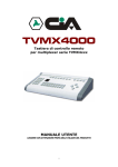
Remote control keyboard for
TVMX4xxx multiplexer series
USER’S MANUAL
READ WITH CARE BEFORE USING THE DEVICE. KEEP FOR FUTURE REFERENCE.
i
TABLE OF CONTENTS
CHAPTER 1 INTRODUCTION .................................................................................. 1
In This Manual ........................................................................................................................ 1
This Remote Keyboard ........................................................................................................... 1
Hardware Overview ................................................................................................................ 2
CHAPTER 2 SYSTEM INSTALLATION & TYPICAL APPLICATIONS..................... 7
System Installation.................................................................................................................. 7
System Configuration and Wiring ........................................................................................... 9
CHAPTER 3 COTROL FUNCTIONS & SETUP & OPERATING PROCEDURES... 13
Setup Procedures ................................................................................................................. 13
Unit Control Function Buttons ............................................................................................... 17
Video Switcher Control Function Buttons ............................................................................. 21
Multi Keyboard Procedures................................................................................................... 24
Remote Comand Set ............................................................................................................ 27
Connector Pin Assignments.................................................................................................. 30
APPENDIX PAGE.................................................................................................... 31
EQUIPMENT SPECIFICATIONS ............................................................................. 32
ii
CHAPTER 1
INTRODUCTION
In This Manual
Overview
This manual covers day-to-day operation of the Remote control keyboard.
This Remote Keyboard
This Remote control keyboard is an accessory for multiplexers and color quads.
It allows the user to control up to 31 units including multiplexers, color quad units, and
video switchers that have 8 camera inputs, 4 monitor outputs and keyboards. A
maximum of four Keyboards can be installed in one system.
Features
Following are some of the features of the Remote control keyboard:
• RS-485 communication.
• Controls from one to 31 units.
• Controls stand-alone color quad units and many types of multiplexer units.
• Designed for desktop use.
• Controls video switchers. (e.g.; 8 camera inputs x 4 monitor outputs)
• Use front buttons to select the desired transmission speed (1200bps, 2400bps,
4800bps, 9600bps).
Note: All multiplexers and quad units should be set to the RS-485 communication
mode and the same baud rate.
Note: Controls all sorts of our brand units including the following:
Color 16-channel duplex/simplex multiplexer
Color 9-channel duplex/simplex multiplexer
Color 4-channel duplex multiplexer
B & W 16-channel duplex/simplex multiplexer
B & W 9-channel duplex/simplex multiplexer
B & W 4-channel duplex multiplexer
Stand-alone Color Quad
8 x 4 Video Switcher
1
Hardware Overview
Hardware
Components
This Remote control keyboard contains easy-to-use control keys on the front and
simple input and output connectors on the back.
The unit provides the primary operator interface. Most operations are one or two
button presses. The following table contains a description for each buttons on the
keyboard.
Use Figure 1 as a reference.
Control
Buttons
7
1
2
5
REMOTE CONTROL KEYBOARD HRW16
SETUP
16CH
9CH
16CH
4CH
B&W
1
2
3
4
5
6
7
8
9
CLEAR
0
2nd
9CH
16CH
UNIT
MON
GROUP
INPUT
SEL
1
REC
B&W
QUAD
4CH
COLOR
ENTER
4
9CH
COLOR 4CH
LIVE
REC
MENU
SET
9CH
3
6
Figure 1. Front
Number
1
Button
SETUP
2
B&W 16CH
B&W 9CH
B&W 4CH
Color 16CH
Description
Pressing the SETUP button enters the setup mode, and the LED
indicator above this button turns ON. Pressing it again exits the setup
mode.
Setup mode operation (unit status button):
This button is available only in the setup mode. If the controlled unit is a
16-channel B&W multiplexer, press this key in the setup mode, and the
LED indicator above this button turns ON.
Setup mode operation (unit status button):
This button is available only in the setup mode. If the controlled unit is a
9-channel B&W multiplexer, press this key in the setup mode, and the
LED indicator above this button turns ON.
Setup mode operation (unit status button):
This button is available only in the setup mode. If the controlled unit is a
4-channel B&W multiplexer, press this key in the setup mode, and the
LED indicator above this button turns ON.
Setup mode operation (unit status button):
This button is available only in the setup mode. If the controlled unit is a
16-channel color multiplexer, press this key in the setup mode, and the
LED indicator above this button turns ON.
Continued on next page
2
Hardware Overview, continued
Control buttons (continued)
Number
Button
Description
2
Color 9CH
Setup mode operation (unit status button):
This button is available only in the setup mode. If the controlled unit is a
9-channel color multiplexer, press this key in the setup mode, and the
LED indicator above this button turns ON.
Color 4CH
Setup mode operation (unit status button):
This button is available only in the setup mode. If the controlled unit is a
4-channel color multiplexer, press this key in the setup mode, and the
LED indicator above this button turns ON.
Quad
Setup mode operation (unit status button):
This button is available only in the setup mode. If the controlled unit is a
stand-alone color quad, press this key in the setup mode, and the LED
indicator above this button turns ON.
3
FULL& REC
Displays the currently selected camera in the full-screen format or
enters the record mode for simplex multiplexer units.
REC
This button is used for all types of multiplexer units.
PIP I
Displays the currently selected camera in the full-screen format with
one camera as an insert picture. This button is used for all types of
multiplexers and quad units.
2x2
Displays four cameras (two by two).
This button is used for all types of multiplexers and quad units.
3x3
Displays nine cameras (three by three).
This button is used for 16-channel and 9-channel multiplexer units.
4x4
Displays 16 cameras (four by four).
This button is used only for 16-channel multiplexer units.
Sequence
This button is the first button pressed for the automatic sequential
switching mode. This button is used for all types of multiplexers and
quad units.
This button freezes the current screen display until this button is
pressed again. This button is used for all types of multiplexers and
quad units.
Changes the video source from live cameras to the VCR input
(playback). This button is used for all types of multiplexers and quad
units.
Pressing Zoom displays a 2x zoom picture of the current camera in fullscreen mode or of the camera in the first window of the multi-screen
mode. Pressing it again exits the zoom mode. This button is used for all
types of multiplexers and quad units.
The SEL button resets the alarm action or enables the secondary
functions of particular buttons.
Recording preview:
Pressing the VCR button after pressing SEL displays video from the
VCR.
Camera assign:
Pressing a camera number after pressing SEL assigns that camera to a
picture in the PIP and multi-screen modes. This button is used for all
types of multiplexer units.
Quad menu setup mode:
This button functions as a set control in the quad menu setup mode.
1
Freeze
VCR
Zoom
SEL (select)
SEL
Continued on next page
3
Hardware Overview, continued
Control buttons (continued)
Number
3
Button
PIPⅡ
3+4
2+8
PIPⅢ
PIPⅣ
Overlay 4
2nd(secondary)
2nd
LIVE REC
LIVE
REC
MENU
MENU
SET
SET
4
Numbers
0
9
CLEAR
Description
Displays up to five cameras in the full screen with four 1/16-size
pictures inset. Cameras can be displayed in any inset picture. This
button is used B&W 16- and 9-channel multiplexer units.
Displays seven cameras, with three 1/4-size pictures and four 1/16-size
pictures. This button is used for B&W 16- and 9-channel multiplexer
units.
Displays ten cameras, with two 1/4-size pictures and eight 1/16-size
pictures. This button is used only for B&W 16-channel multiplexer units.
Displays the currently selected camera in full-screen format with two
inset pictures. This button is used only for color 4-channel multiplexer
units.
Displays the currently selected camera in the full-screen format with
three inset pictures. This button is used only for color 4-channel
multiplexer units.
Displays the currently selected camera in the full-screen format with
four inset pictures. This button is used only for color 9-channel
multiplexer units.
Pressing this button changes the Primary display buttons to secondary
display buttons. This button is used for color multiplexer units.
The output to the VCR is changed to record only the selected camera
instead of multiplexed video output. This button is used for all types of
multiplexer units.
The menu button is used to enter and exit the menu setup mode. This
button is used for color multiplexers and quad units.
This button functions as a set control in the menu setup mode. This
button is used for all types of multiplexer units.
Setup mode operation:
Used to select units 01 through 98 during the setup mode.
Unit and video switcher selection mode operation:
Used to select the controlled unit with the UNIT button, and input and
output with MON, GROUP and INPUT buttons in the video switcher.
Unit control mode operation:
Used with the ENTER button to transmit a function to the selected unit.
Used with the SEL button to position cameras on the screen in the PIP
and multi-screen modes. These buttons are also used to select
cameras to view full-screen mode and to setup the activity detection
grids in the menu setup mode.
Used to clear a numeric entry.
CLEAR
ENTER
ENTER
Transmit command:
Press the number buttons and then press this button.
Continued on next page
4
Hardware Overview, continued
Control buttons (continued)
5
UNIT
MON
GROUP
INPUT
6
Arrows
7
Dual digit
display
The UNIT button enters this remote keyboard to the multiplexer & quad
control mode and unit number selection mode.
The MON button switches the remote keyboard into the monitor
selection mode of the video switcher.
In the monitor selection mode, this button is used to go out the group of
the input video signals from G1(video in 1+5) to G4(video in 4+8) to the
associated monitors with the current selected monitor
In the monitor selection mode, this button is used to go out an input
video signal (video in 1~8) to the current selected monitor.
The arrow buttons act as the DOWN, UP, LEFT and RIGHT arrow
buttons in the MENU setup mode and Zoom mode.
Displays the unit number of the multiplexer, quad or the monitor output
number of the video switcher. Also displays the keyboard ten-key
processing.
The table below contains a description for each connector on the back of the
Remote control keyboard.
Use Figure 2 as a reference.
Back
-
+
ON OFF
POWER TERMINATION
IN
SWITCH
DC 9V
1
2
RS485
OUT
3
Figure 2. Back
Part
1
Label
Power
2
Termination
Switch
RS-485
(IN / OUT)
3
Function
This 2.1mm pin jack accepts 9VDC, 0.6Amps.
The center pin is positive.
If this is the first or last device on the network, terminate the device with
a 100Ωterminative resistor.
This RJ-45 connector provides RS-485 communications.
Pin assignment:
Pin 1,2,3,5,7,8 – no connections
Pin 4 – RXB (for RS-485)
Pin 6 – RXA (for RS-485)
Continued on next page
5
Hardware Overview, continued
RS-485 cable
Specifications
The length of supplied cable is 6 meters (19.7 feet).
Note: The RS-485 network is a multi-drop, wiring configuration, maximum length
3000 Feet (1000meters). RJ45 connectors are used for most hookups. If
you are making your own cable, it must meet the following specification:
#24 AWG, twisted one-pair with shield (2-wire).
Less than 16pF per foot, nominal.
Less than 25 ohms per 100 ft, nominal.
Pin 1,2,3,5,7,8 : No connections
Pin 4 : RXB (for RS-485)
Pin 6 : RXA (for RS-485)
Length : 6m (19.70ft)
RS-485
Cable pin
Assignments
RJ45 Modular Cable (6m)
8
1
4:RXB
6:RXA
4:RXB
6:RXA
1
8
Figure 3. RJ45 Modular cable & Pin assign
Termination
cable
This termination cable should be connected to the last unit controlled by this
Remote control keyboard.
Termination
Cable pin
assignments
Pin 3, 4 short.
RXS, RXB short.
Termination Cable (30mm)
8
4:RXB
3-4 Short: RXS-RXB
3:RXS
1
Figure 4. RJ45 Modular cable & Pin assign
6
CHAPTER 2
SYSTEM INSTALLATION & TYPICAL APPLICATIONS
System Installation
Keyboard Installation
Before you start connecting the keyboard equipment to your system, make sure the
units to be controlled (multiplexers, quads, etc.) are completely installed and
everything is working correctly.
You must be set the communication protocol and unit number of the controlled units.
The Remote control keyboard’s only method of communication is RS-485. Select the
desired baud rate (1200bps, 2400bps, 4800bps, 9600bps) in unit option setup mode.
1200bps is default setting. Select the desired unit number, from 01 to 98.
Use the following steps to set the communication protocol and unit number.
Color Multiplexer unit setting
The main menu of the color multiplexer provides access to all programming options.
In this mode, select “9. Unit option.”
The UNIT OPTION setup screen allows you to make changes to the unit’s options.
In this mode, you can set up the unit number and communication method.
Unit Number setting
Select the desired number from 001 to 098.
Communication setting
Select the RS485 option and the desired baud rate option. 1200bps is the keyboard
default setting.
Note: The baud rate must be the same between the controlled unit and the keyboard.
UNIT OPTION
MIAN MENU
1. Time, Date Setup
2. Display Setup
3. sequence Setup
4. Recording Setup
5. Camera Setup
6. Alarm Input Setup
7. Schedule, Alarms Setup
8. Dynamic Scene Sensing Setup
9. Unit Option
Password:
Enter new code:
Re-enter code:
Unit Number:
Factroy Reset:
Key Lock:
Alarm History List:
Communication:
Picture Setup:
OFF
* * * *
* * * *
001
NO
OFF
Communication
Type:
RS485
Baud Rate: 1200bps
Port:
On
Continued on next page
7
System Installations, continued
B&W Multiplxer unit setting
The main menu of the B&W multiplexer provides access to all programming options.
In this mode, select “9. Security Setup”.
The SECURITY OPTION setup screen allows you to make changes to the unit’s options.
In this mode, you can set up the unit number.
Unit Number setting
Select the desired number from 01 to 98.
Communication setting
There is no way to change communication setting. The baud rate is 1200bps.
SECURITY OPTION
MAIN MEMU
Password:
OFF
Enter New Code: * * * *
Re-enter Code:
* * * *
Unit Number:
01
Factory Reset:
NO
Key Lock:
OFF
Alarm Count Display:
1. Time, Date Setup
2. Camera Title
3. Sequence Setup
4. Recording Setup
5. Cameras to Record
6. Alarm Input Setup
7. Alarm Setup
8. Activity Detection Setup
9. Security Setup
MENU SET CAM(1-10)
MENU SET CAM(1-16)
Color Quad unit setting
The main menu of the color quad provides access to all programming options.
In this mode, select “7. Configuration”.
The CONFIGURATION setup screen allows you to make changes to the unit’s
options. In this mode, you can set up the unit number and communication method.
Unit Number setting
Select the desired number from 01 to 98.
Note: Make certain the number is not used for any other controlled unit.
Communication setting
Select the RS485 option, and set the desired baud rate. The default setting for the
keyboard is 1200bps.
MAIN MENU
1. LANGUAGE
2. TIME, DATE
3. CAMERA
4. ALARM
5. SEQUENCE
6. PICTURE ADJUST
7. CONFIGURATION
CONFIGURATION
1. PASSWORD:
OFF
2. ENTER NEW CODE:
---RE-ENTER NEW CODE:- - - 3. FACTORY DEFAULT:
NO
4. KEY LOCK:
OFF
5. VCR INPUT:
BNC
6. REMOTE CONTROL
7. ALARM COUNT DISPLAY
8. VIDEO SETUP
8
REMOTE CONTROL
1. UNIT NUMBER:
01
2. DATA RATE:
1200BPS
System Configuration and Wiring
System Configuration
This Remote keyboard system must be installed by qualified service and installation
personnel. The installation must be in accordance with all local and federal electrical
and building codes.
There are two methods of installation depending on the number of Remote keyboard
used. When using one Remote keyboard controlled system, use the Single Keyboard
Configuration method. When installing two to four keyboards, use the Multi Keyboard
Configuration method.
Perform the following steps to install the Remote keyboard system.
A. Unpack all components.
B. Place the Remote keyboard in a convenient location.
Note: Carefully and completely read the manuals for each piece of equipment before
attempting to install and connect the equipment.
Note: The main power jack on the rear of the keyboard must be disconnected before
the RJ45 modular cable is plugged into the RS-485 connector, The other end
of the cable plugged into RJ45 modular connectors on the rear of the
controlled units (multiplexers, quads, etc.).
C. Decide on the configuration method.
D. Rout the RJ45 cable from the Remote keyboard to the Controlled units according
to the Single or Multi Keyboard Configration.
CAUTION: If the provided RJ45 modular cable is not long enough, do not substitute a
telephone cable. Using a telephone cable could damage the Remote
keyboard and /or the controlled unit.
F. Use one of the following sections to configure the wiring.
Continued on next page
9
System Configuration and Wiring, continued
Single Keyboard Configuration
Use the Single Keyboard Configuration when only one keyboard is connected to the
controlled units. Connect the RS-485 output port of Remote keyboard to RS-485 input
port of the first controlled unit using the RJ45 modular cable. Turn on the termination
switch of Remote keyboard. The controlled units can be daisy-chained by connecting
the output RS-485 modular connector of the first controlled unit to the input RS-485
modular connector on the next unit. Plug the termination cable into output port of the
last controlled unit. One Remote keyboard can control up to 31 units.
Use Figure 5a. as a reference.
IN
OUT
Remote Keyboard
Termination
Switch ON
: RS485 cable
MAIN
Multiplexer
& Quad unit
SPOT
IN
RS-485
OUT
MAIN
Multiplexer
& Quad unit
SPOT
IN
RS-485
OUT
MAIN
Multiplexer
& Quad unit
SPOT
IN
RS-485
OUT
Other unit or Termination cable
Figure 5a. System wiring single keyboard
Continued on next page
10
System Configuration and Wiring, continued
Multi Keyboard Configuration
The Multi Keyboard Configuration method is used when connecting two to four
Remote keyboards with controlled units. Connect the RS-485 output port of the first
Remote keyboard to RS-485 input port of the first controlled unit using the RJ45
modular cable.
The controlled units can be daisy-chained by connecting the output RS-485 modular
connector of the first controlled unit to the input RS-485 modular connector on the
next unit. Plug the termination cable into output port of the last controlled unit.
The remaining Remote keyboards and, controlled units are wired the same way.
Connect the output modular connector of each Remote keyboard to the input
modular connector of the next Remote keyboard. Turn ON the termination switch of
the last Remote keyboard. Make certain to turn OFF the termination switches on the
rest of the Remote keyboards.
Up to 31 controlled units can be connected to a maximum of four Remote control
keyboards.
Use Figure 5b. as a reference.
: RS485 cable
MAIN
Multiplexer
& Quad unit
SPOT
IN
RS-485
OUT
IN
OUT
Remote Keyboard
Termination
Switch OFF
MAIN
Multiplexer
& Quad unit
SPOT
IN
RS-485
OUT
IN
OUT
Remote Keyboard
MAIN
Multiplexer
& Quad unit
SPOT
IN
RS-485
Termination
Switch OFF
OUT
IN
MAIN
Multiplexer
& Quad unit
SPOT
OUT
Remote Keyboard
IN
RS-485
OUT
Termination
Switch OFF
MAIN
Multiplexer
& Quad unit
SPOT
IN
RS-485
IN
OUT
Remote Keyboard
OUT
Termination
Switch ON
Other unit or Termination cable
Figure 5b. System wiring multi-keyboards
Continued on next page
11
System Configuration and Wiring, continued
System configuration with Video Switcher
8 x 4 Video Switcher
The video switcher is only controlled by the Remote control keyboard. This unit has
eight video-inputs and four monitor-outputs. Video input sources come from
controlled units main and spot video outputs. Video outputs are connected to
standard video monitors.
Refer to the 8x4 Video Switcher manual for the detailed operation.
Use Figure 6 as a reference.
Multiplexer
& Quad unit (unit#2)
Multiplexer
& Quad unit (unit#1)
MAIN
MAIN
IN
SPOT
RS-485
OUT
Multiplexer
& Quad unit (unit#3)
MAIN
SPOT
IN
RS-485
IN
SPOT
OUT
MAIN
Multiplexer
& Quad unit (unit#4)
OUT
RS-485
SPOT
IN
RS-485
OUT
Other unit or
Termination cable
input MAIN
IN
input SPOT
RS-485
OUT
8 x 4 Video Switcher
output MONITOR
IN
Remote Keyboard
OUT
Termination
Switch ON/OFF
Monitor #1,2,3,4
Other Remote keyboard
Figure6. System wiring with Video Switcher
12
CHAPTER 3
CONTROL FUNCTIONS, SETUP OPERATING PROCEDURES
Setup Procedures
Overview
This Remote control keyboard transmits commands to multiplexers, quads and
video switchers via RS-485 modular cables
Power up
Action
When the power is applied to the Remote keyboard, all LED indicators and the
dual digit display of the unit will light for two seconds during the self-test. After
self-test, the dual digit display show the default unit number (01). The UNIT LED
indicator and the LEDs above the unit status buttons turn ON.
Note: The Remote keyboard must be turned on after all controlled units
(multiplexers, quads, etc.) are activated.
Note: The default unit status is the color 16-channel multiplexer.
Unit Setup
The seven unit statuses are as follows:
Status
Color 16-channel duplex/simplex multiplexer
Color 9-channel duplex/simplex multiplexer
Color 4-channel duplex multiplexer
B&W 16-channel duplex/simplex multiplexer
B&W 9-channel duplex/simplex multiplexer
B&W 4-channel duplex multiplexer
Stand-alone color quad
Button process
COLOR 16CH
COLOR 9CH
COLOR 4CH
B&W 16CH
B&W 9CH
B&W 4CH
Quad
Select the setup mode depending on the type of controlled unit. If all the
controlled units are the same type, select the all units setup mode. However, if the
controlled units are various types, perform the individual unit setup operation. Use
the following section to perform the unit setup operation.
All units setup mode
Button(s)
SETUP
CLEAR
Unit Status
ENTER
Action
Press the SETUP button to enter unit status setup mode. Then
SETUP LED indicator is ON and UNIT LED indicator is OFF.
Press SETUP again to exit the unit setup mode and return to
the unit control mode.
Press the CLEAR button. The auto setup message “AS”
displays on the dual digit display, and the unit status LED
indicator turns off.
To cancel press CLEAR again to exit the auto setup mode and
return to the unit control mode.
Press the unit status button for the appropriate unit type (e.g.;
B&W 16CH, Color 9CH). To cancel press the CLEAR button to
exit the all units setup mode and return to the unit control mode.
Press the ENTER button. The remote keyboard performs the all
unit setup and then returns to the unit control mode.
Continued on next page
13
Setup Procedures, continued
Unit Setup (continued)
All unit setup mode (example)
Example 1: When all units are Color 16-channel multiplexers.
Dual-digit
Dual-digit
Dual-digit
UNIT
Color 16CH
SETUP
CLEAR
16CH
Unit control mode
UNIT
ENTER
Color 16CH
Unit control mode
COLOR
exit Unit Setup,
return Unit control mode
enter All setup mode
Example 2: When all units are B&W 16-channel multiplexers.
Dual-digit
Dual-digit
Dual-digit
UNIT
Color 16CH
SETUP
CLEAR
16CH
Unit control mode
ENTER
B&W
enter All setup mode
UNIT
B&W 16CH
Unit control mode
exit Unit Setup,
return Unit control mode
Individual unit setup mode
This mode is used to assign the status of each unit. The unit status is made up of
all multiplexer types and stand-alone color quads. The SETUP button enters the
setup mode. Pressing it again exits the setup mode. When you exit the setup
mode, you are immediately returned to the unit control mode.
Use the following steps to assign unit address numbers for the multiplexers and
quas.
STEP 1. Assign the unit numbers and list of the unit address numbers.
The user must assign the unit numbers to the multiplexers and quads in use.
Next, make a list of the unit address numbers.
STEP 2. Set up the unit number in at the unit option setup menu.
Using the list made in STEP1, set up the unit number of the multiplexers and
quads in the unit option setup of menu.
STEP 3. Assign the unit status for remote keyboard.
The user must program the unit status for each unit into the remote keyboard.
Use the following steps to assign unit status for each unit. Below is an example
for assigned unit status. In this example, unit number 05 is assigned to a color
16-channel multiplexer.
Note: None of the status programming changes made are saved until you press
ENTER.
Continued on next page
14
Setup Procedures, continued
Unit Setup (continued)
Individual unit setup mode (continued)
Button(s)
Action
SETUP
Press the SETUP button to enter the unit status setup mode.
The SETUP LED indicator turns ON and UNIT LED indicator is
OFF.
Pressing SETUP again to exit the unit status setup mode and
return to the unit control mode.
Numbers or
Press the Number buttons to assign the desired unit number
(05). The selected unit number is displayed on the dual digit
UP( ↑) /
display. Pressing the UP or DOWN buttons will move to the next
DOWN( ↓)
or previous unit number.
COLOR 16CH
Press the COLOR 16CH button (unit status button) to assign a
16-channel multiplexer for the configuration of unit number 05.
The COLOR 16CH LED indicator turns On.
ENTER
Press the ENTER button to save the status of unit number 05.
The dual-digit displays the next unit number (06).
Note: If you want to assign another unit configuration, repeat
above the procedures.
SETUP
Pressing the SETUP button turns off the unit setup mode. The
SETUP LED indicator turns OFF. The Keyboard is immediately
returned to the unit control mode. The UNIT LED indicator turns
On.
Individual unit setup mode (example)
Example 1: Unit number list (#1-C16, #2-C9, #3-B&W16, #4-Quad continuou setup)
Unit number list
#1 : Color 16ch MUX
#2 : Color 9ch MUX
#3 : B&W 16ch MUX
#4 : Color Quad
Dual-digit
UNIT
Color 16CH
Unit control mode
Dual-digit
1
0
SETUP
16CH
ENTER
COLOR
enter Unit Setup mode
Dual-digit
Unit#1 Setup
Dual-digit
9CH
Dual-digit
16CH
ENTER
COLOR
ENTER
QUAD
ENTER
B&W
Unit#2 Setup
Unit#3 Setup
Unit#4 Setup
Dual-digit
Dual-digit
SETUP
UNIT
Color 16CH
Unit control mode
exit Unit Setup,
return Unit control mode
Continued on next page
15
Setup Procedures, continued
Unit Setup (continued)
Individual unit setup mode (example continued)
Example 2: Unit number list (#15-Color 16CH MUX →B&W 16CH MUX setup)
Dual-digit
UNIT
Color 16CH
Unit control mode
Dual-digit
Dual-digit
SETUP
16CH
UNIT
SETUP
ENTER
Color 16CH
Unit control mode
B&W
exit Unit Setup,
return Unit control mode
Unit Setup mode Unit#15 apart Setup
This mode is used to control the unit as a multiplexer or quad. This mode is made
up of two parts: one is the unit selection and the other is unit control.
Operating
Procedures
Note: The UNIT LED indicator turns ON. This indicator the keyboard is in unit
control mode. If the UNIT LED indicator blinks, it indicates the keyboard is
in unit selection mode.
. Use the following steps to select the unit number.
Unit Selection
Button(s)
UNIT
Numbers or
UP( ↑) /
DOWN( ↓)
ENTER
Action
Press UNIT while in the unit control mode. The UNIT LED
indicator blinks. Pressing it again to exit unit selection and
return to the unit control mode.
Press the Number buttons to assign the desired unit number.
The selected unit number is displayed on the dual digit display.
Pressing the UP or DOWN buttons will move to the next or
previous unit number.
Press the ENTER button to save the selected unit number. The
UNIT LED indicator stops blinking and turns ON.
Example: Unit Selection (#1-Color 16CH MUX →#15 B&W 16CH MUX selection)
Dual-digit
Dual-digit
blinking
UNIT
Color 16CH
Unit control mode
1
UNIT
5
ENTER
UNIT
B&W 16CH
Unit control mode
exit Select Unit number
return Unit control mode
Continued on next page
16
Setup Procedures, continued
Unit Control
Unit Control is related to the configuration of unit. There are seven types of unit
control. The Keyboard has keys for all possible types of controlled units.
Configuring the keyboard determines which keys will be enabled for each unit.
Use the following information as a guide for the enabled buttons for various unit
configurations.
Unit Control Function Buttons
Color 16-Channel Duplex & Simplex Multiplexer Functions
The enabled buttons for a color 16-channel multiplexer displayed below with thick
lines. The remaining buttons are disabled while in the color 16-channel
multiplexer control mode.
Refer to the Color 16-channel duplex & simplex multiplexer manual for detailed
operations.
Note: In the multi keyboard system, the repeat operation of arrow button is
disabled.
SEL
1
REC
2nd
B&W
9CH
16CH
COLOR 4CH
LIVE
REC
MENU
SET
9CH
Figure 7. Color 16-channel multiplexer control buttons
Color 9-Channel Duplex & Simplex Multiplexer Functions
The enabled buttons for a color 9-channel multiplexer are displayed below with
thick lines. The remaining buttons are disabled while in the color 9-channel
multiplexer control mode.
Refer to the Color 9-channel duplex & simplex multiplexer manual for detailed
operations.
Note: In the multi keyboard system, the repeat operation of arrow button is
disabled.
SEL
1
REC
2nd
B&W
9CH
16CH
COLOR 4CH
LIVE
REC
MENU
SET
9CH
Figure 8. Color 9dchannel multiplexer control buttons
Continued on next page
17
Unit Control Function Buttons, continued
Color 4-channel Duplex Multiplexer Functions
The enabled buttons for a color 4-channel multiplexer are displayed below with
thick lines. The remaining buttons are disabled while in the color 4-channel
multiplexer control mode.
Refer to of the Color 4-channel duplex & simplex multiplexer manual for detailed
operations.
Note: In the multi keyboard system, the repeat operation of arrow button is
disabled.
SEL
1
REC
2nd
B&W
9CH
16CH
COLOR 4CH
LIVE
REC
MENU
SET
9CH
Figure 9. Color 4-channel multiplexer control buttons
B&W 16-channel Duplex & Simplex Multiplexer Functions
The enabled buttons for a B&W 16-channel multiplexer are displayed below with
thick lines. The remaining buttons are disabled while in the B&W 16-channel
multiplexer control mode.
Refer to the B&W 16-channel duplex & simplex multiplexer manual for operations.
Note: In the multi keyboard system, the repeat operation of arrow button is
disabled.
SEL
1
REC
2nd
B&W
9CH
16CH
COLOR
4CH
LIVE
REC
MENU
SET
9CH
Figure 10. B&W 16-channel multiplexer control button
Continued on next page
18
Unit Control Function Buttons, continued
B&W 9-channel Duplex & Simplex Multiplexer Functions
The enabled buttons for a B&W 9-channel multiplexer are displayed below with
thick lines. The remaining buttons are disabled while in the B&W 9-channel
multiplexer control mode.
Refer to the B&W 9-channel duplex & simplex multiplexer manual for detailed
operations.
Note: In the multi keyboard system, the repeat operation of arrow button is
disabled.
SEL
1
REC
2nd
B&W
9CH
16CH
COLOR
4CH
LIVE
REC
MENU
SET
9CH
Figure 11. B&W 9-channel Multiplexer control buttons
B&W 4-Channel Multiplexer Functions
The enabled buttons for a B&W 4-channel multiplexer are displayed below with
thick lines. The remaining buttons are disabled while in the B&W 4-channel
multiplexer control mode.
Refer to the B&W 4-channel duplex & simplex multiplexer for detailed operations.
Note: In the multi keyboard system, the repeat operation of arrow button is
disabled.
SEL
1
REC
2nd
B&W
9CH
16CH
COLOR
4CH
LIVE
REC
MENU
SET
9CH
Figure 12. B&W 4-channel Multiplexer control buttons
Continued on next page
19
Unit Control Function Buttons, continued
Stand-alone Color Quad Functions
The enabled buttons for a stand-alone color are displayed below with thick lines.
The remaining buttons are disabled while in the stand-alone color quad control
mode.
Refer to of the stand-alone Color Quad manual for detailed operations.
Note: In the multi keyboard system, the repeat operation of arrow button is
disabled.
SEL
1
REC
2nd
B&W
9CH
16CH
COLOR
4CH
LIVE
REC
MENU
SET
9CH
Figure 13. Stand-alone Color Quad control buttons
ENTER button operations
This button not exists in the multiplexer and quad units. This button should be
pressed after pressing the camera number buttons. Use the following section to
perform the ENTER button operations.
Full operation
This operation is applied to for all type of multiplexer and quad units.
Example: When you want to display the screen of camera 2 in the full-screen mode, press
as below.
0
2
ENTER
Sequence operation of the color multiplexer
This operation is applied to for only color multiplexer units.
Example: When you want to sequence in order of the sequence 1 mode, press as below.
1
1
ENTER
Camera assign operation
This operation is applied to for all type of multiplexer units.
Example: When you want to assign cameras (background is camera #1 and inset picture
is camera #2), press as below. This operation is applied to for all multi screen
modes.
SEL
1
ENTER
2
ENTER
Continued on next page
20
Unit Control Function Buttons, continued
Live Record operation
This operation is applied to for all type of multiplexer units.
Example: When you want to record only the selected camera (#2), press as below.
LIVE
REC
2
ENTER
Menu setup mode operation
At the setup mode, entering the password or changing the password, This button should
be pressed after pressing the camera number buttons. This operation is applied to for all
types of multiplexers and quad units.
Example: If you wanted password is “1 2 3 4”, press as below.
1
ENTER
2
3
ENTER
ENTER
4
ENTER
Video Switcher Control Function Buttons
Video Switcher
Control Mode
This mode is used to control the 8x4 Video switcher. The Video switcher mode is
made up of the monitor output, single video input and group video input controls.
Refer to of the 8x4 Video Switcher manual for the detailed operations.
Monitor Output
Control
This mode is used to control the monitor output video on the video switcher.
Use the following steps to select the output monitor of the video switcher.
The default monitor number is 01.
Button(s)
MON
Numbers or
UP( ↑) /
DOWN( ↓)
ENTER
Action
Press the MON button. The MON LED indicator turns ON and
the UNIT LED indicator turns OFF. Then the previously selected
monitor number is displayed on the dual digit display.
Press the Number buttons to assign the desired monitor output
number. The selected monitor output number is displayed on
the dual digit display. Pressing the UP or DOWN buttons will
move to the next or previous monitor output number.
Press the ENTER button to save and transmit the selected
monitor output number.
Example: Monitor number Selection (MON#01 →MON#04)
Dual-digit
Dual-digit
Dual-digit
UNIT
Color 16CH
0
MON
4
MON
ENTER
Unit control mode
Color 16CH
Monitor Selection
Monitor
Selection mode
Monitor#4 select
Continued on next page
21
Video Switcher Control Function Buttons, continued
Individual video
Input Selection
Mode
This mode is used to control the individual video input on the video switcher.
Use the following steps to select the input video.
The default input video number is 01.
Button(s)
INPUT
Numbers or
UP( ↑) /
DOWN( ↓)
ENTER
EXAMPLE
Action
Press the INPUT button. The INPUT and MON LED indicators
turn ON, and the UNIT LED indicator turns OFF. Then the
previously selected monitor number is displayed on the dual digit
display.
Press the Number buttons to assign the desired input video. The
currently selected video input number is displayed on the dual
digit display. Pressing the UP or DOWN buttons will move to the
selected video input number.
Press the ENTER button to save and transmit the selected video
input number. The previously monitor output number returns to
the dual digit display.
The operating procedure is as follows:
1.The video switcher has a unit ID 01.
2.The main output of the multiplexer with unit number 01 is
connected to input 1 on this switcher.
3.The main output of the multiplexer with unit number 02 is
connected to input 2 on this switcher.
4.The output number 1 of the switcher is connected to monitor 1.
5.The output number 2 of the switcher is connected to monitor 2.
6.The switcher was set to monitor 1.
Pressing the INPUT button and the monitor output number 01
display on the dual digit display. Enter the input video number 01
using the Number buttons. Continuously press the ENTER
button. You should see the main output of the multiplexer 01 on
monitor 1.
The selected monitor output number 01 displays on the dual digit
display. Enter the input video number 02 using the Number
buttons. The input video number 02 displays on the dual digit
display. Continuously press the ENTER button. You should see
the main output of the multiplexer 02 on monitor 1. The dual digit
display returns to the previous monitor output number 01.
Example: Input number selection (at MON#04, display INPUT#02)
Dual-digit
UNIT
Color 16CH
0
INPUT MON
Unit control mode
Dual-digit
Dual-digit
Dual-digit
2
ENTER
MON
INPUT
Monitor Selection
MON#4 display
Input Selection
mode
Input#02 select
Continued on next page
22
Video Switcher Control Function Buttons, continued
This mode is used to select the input video from a group on the video switcher.
Use the following steps to select the grouped input video.
The default input video number is 01.
Input video
Selection
In a group
Mode
Button(s)
GROUP
Number or
UP( ↑) /
DOWN( ↓)
ENTER
EXAMPLE
Action
Press the GROUP button. The GROUP and MON LED indicators
turn ON and the UNIT LED indicator turns OFF. Then the
previously selected monitor number displays on the dual digit
display.
Press the Number buttons to assign the desired group video. The
currently selected group video number displays on the dual digit
display. Pressing the UP or DOWN buttons will move to select
group video number.
Press the ENTER button to save and transmit the selected group
video number. The selected monitor output number returns to the
dual digit display.
The operating procedure is as follows:
1.The video switcher unit ID is 01.
2.The main output of the multiplexer 01 is connected to input 1
on the switcher.
3.The spot output of the multiplexer 01 is connected to input 5 on
the switcher.
4.The main output of the multiplexer 02 is connected to input 2
on the switcher.
5.The spot output of the multiplexer with unit number 02 is
connected to input 6 on the switcher.
6.The output number 1 of the switcher is connected to monitor 1.
7.The output number 3 of the switcher is connected to monitor 3.
8.The switcher was set to monitor 1 or 3.
Press the GROUP button. The monitor output number 01 will be
displayed on the dual digit display. Enter the group video number
01 using the Number buttons. Continuously press the ENTER
button. You should see the main and spot outputs of the
multiplexer 01 on monitors 1 and 3.
Press the GROUP button. The selected monitor output number
01 displays on the dual digit display. Enter the group video
number 02 using the Number buttons. Group video number 02
displays on the dual digit display. Continuously press the ENTER
button. You should see the main and spot outputs of multiplexer
02 on the monitors 1 and 3. The dual digit display returns to the
previous monitor output number 01.
Example: Group number selection (at MON#01 & 03, display GROUP#02 & 06)
Note: In the Group input mode, the input or output is a pair of ports. Refer to the
8x4 Video Switcher manual for the detailed operations.
Dual-digit
Dual-digit
Dual-digit
Dual-digit
0
UNIT
Color 16CH
GROUP MON
Unit control mode
2
ENTER
OR
Dual-digit
Dual-digit
Group Selection
mode
0
MON# display
23
4
OR
Dual-digit
MON
GROUP
Monitor Selection
Multi Keyboard Procedures
Keyboard ID
setting
Multiple keyboards can be used. Two to four Remote keyboards can be
connected and configured. You must assign each keyboard an ID number.
The default keyboard ID number is U0.
Note: The keyboard ID numbers are U0, U1, U2 and U3 in order. The user must
set the ID number to avoid duplicated numbers.
Use the following steps to set the keyboard ID number.
Button(s)
SETUP
UNIT
Number
ENTER
CLEAR
Action
Press the SETUP button. The SETUP LED indicator turns ON
and UNIT LED indicator turn OFF.
Press the UNIT button to enter the keyboard ID setup mode.
The SETUP LED and UNIT LED indicators turn ON.
Use the Number buttons to assign the desired the keyboard ID.
Note: The first keyboard ID displays 00 on the dual digit display,
the second displays as 01, the third displays as 02 and
the last displays as 03.
Press the ENTER button to save the keyboard ID. The selected
keyboard ID code displays on the dual digit display.
Note: The first keyboard ID displays as U0, the second displays
as U1, the third displays as U2 and the last keyboard ID
displays as U3.
Press the CLEAR button to confirm the keyboard ID. The
keyboard ID number displays on the dual digit display for a
short time. Then, the dual digit display returns the previous the
controlled unit number.
Example 1: Keyboard ID setting (ID “U0”)
exit Keyboard ID Setup,
return Unit control mode
Dual-digit
Dual-digit
UNIT
Color 16CH
UNIT
Unit control mode
Color 16CH
Unit control mode
Dual-digit
SETUP
UNIT
0
0
ENTER
ID "U0" setup
Example 2: Keyboard ID setting (ID “U3”)
exit Keyboard ID Setup,
return Unit control mode
Dual-digit
Dual-digit
UNIT
Color 16CH
UNIT
Unit control mode
Color 16CH
Unit control mode
Dual-digit
SETUP
UNIT
3
0
ID "U3" setup
24
ENTER
Continued on next page
Multi Keyboard Procedures, continued
Polling check
After power up, the Polling check mode starts polling the network. If the Remote
keyboard system detects that remote keyboards have been added or deleted
while polling the network, it will automatically change the highest available
keyboard ID.
Use the following steps to check the keyboard polling procedure.
Note: The polling check mode will be performed by the first keyboard ID U0.
Button(s)
SETUP
SET
Action
Press the SETUP button. The SETUP LED indicator turns ON
and UNIT LED indicator turns OFF.
Press the SET button. The SETUP LED indicator turns OFF and
the Polling Check mode Starts. The dual digit displays the
Polling Check results. It displays U0, U1, U2 andcU3 in order at
regular intervals. After the Polling Check procedure, the multi
keyboard polling process starts.
Example: Polling Check (Keyboard ID U0, U1, U2, U3)
Dual-digit
Keyboard ID setup
SET
SETUP
Polling operation
UNIT
Color 16CH
Unit control mode
exit Polling Check,
return Unit control mode
Dual-digit
Dual-digit
Dual-digit
Dual-digit
Dual-digit
Dual-digit
Dual-digit
Dual-digit
Dual-digit
Dual-digit
dual-digit display at Polling procedure
Continued on next page
25
Multi Keyboard Procedures, continued
Baud Rate
setting
Select the desired operating speed (1200bps, 2400bps, 4800bps, 9600bps) using
the front buttons.
1200bps is the default setting. If you want to check the baud rate during operation,
press the CLEAR button. The dual-digit displays the baud rate.
Note: All multiplexers and quad units should be set up gor RS-485 communications
and all must be set at the same baud rate.
Use the following steps to select the baud rate.
Button(s)
SETUP
UNIT
Numbers
ENTER
CLEAR
Action
Press the SETUP button. The SETUP LED indicator turns ON
and the UNIT LED indicator turns OFF.
Press the UNIT button to enter the baud rate setup mode. The
SETUP LED and UNIT LED indicators turn ON.
Press the Number buttons to assign the desired baud rate.
Note: 1200bps is displayed as “12” on the dual digit display.
2400bps is displayed as “24,” 4800bps is displayed as “48”
and 9600bps is displayed as “96.”
Press the ENTER button to save the selected baud rate. The
selected baud rate code is displayed on the dual digit display.
Note: 1200bps is displayed as C1. 2400bps is displayed as C2,
4800bps is displayed as C3 and 9600bps is displayed as
C4.
Press the CLEAR button to confirm the baud rate. The baud
rate displays the dual digit display for a short while. Then the
dual digit display returns to the previous controlled unit number.
Example: Baud-rate setting (Keyboard ID U0, U1, U2, U3)
Dual-digit
Dual-digit
UNIT
Color 16CH
SETUP
UNIT
2
4
ENTER
Unit control mode
Dual-digit
UNIT
Color 16CH
Unit control mode
exit Change Baud-rate
return Unit control mode
Example: Check Baud-rate and Keyboard ID (1200bps and U0)
Dual-digit
Baud-rate, ID
UNIT
Color 16CH
CLEAR
Unit control mode
Dual-digit
Dual-digit
Dual-digit
UNIT
Color 16CH
Unit control mode
at no Ten button
exit Check Baud-rate & ID,
return Unit control mode
26
Remote Command Set
Remote
Command Set
Each remote commands consists of three ASCII characters. The command sets
are as follows:
1. Color 16-channel duplex and simplex multiplexer
2. Color 9-channel duplex and simplex multiplexer
3. Color 4-channel duplex multiplexer
4. B&W 16-channel duplex and simplex multiplexer
5. B&W 9-channel duplex and simplex multiplexer
6. B&W 4-channel duplex multiplexer
7. Stand-alone color quad
8. 8 x 4 Video Switcher
Remote Keyboard Command Set list
Color 16-Channel Duplex and Simplex Multiplexer
Equivalent Button Press
Command
MENU
@ME
SELECT
@SL
VCR (REVIEW)
@VR
LIVE RECORD
@LR
FULL
@FL
@PP
PIPⅠ
2x2
@22
3x3
@33
4x4
@44
SEQUENCE
@SQ
Equivalent Button Press
FREEZE
ZOOM
2ND
SET
CAM 1 – 16(Numbers)
Unit number (Numbers)
DOWN
UP
LEFT
RIGHT
Command
@FR
@ZO
@SN
@SE
@01 - @16
#000 - #255
@PP
@22
@33
@44
Color 9-Channel Duplex and Simplex Multiplexer
Equivalent Button Press
Command
MENU
@ME
SELECT
@SL
VCR (REVIEW)
@VR
LIVE RECORD
@LR
FULL
@FL
@PP
PIPⅠ
2x2
@22
3x3
@33
Overlay 4
@O4
SEQUENCE
@SQ
Equivalent button press
FREEZE
ZOOM
2ND
SET
CAM 1 – 9(Numbers)
Unit number (Numbers)
DOWN
UP
LEFT
RIGHT
Command
@FR
@ZO
@SN
@SE
@01 - @09
#000 - #255
@PP
@22
@O4
@33
Color 4Channel Duplex and Simplex Multiplexer
Equivalent Button Press
Command
MENU
@ME
SELECT
@SL
VCR (REVIEW)
@VR
LIVE RECORD
@LR
FULL
@FL
@P1
PIPⅠ
@P2
PIPⅢ
@P3
PIPⅣ
2x2
@22
SEQUENCE
@SQ
Equivalent Button Press
FREEZE
ZOOM
2ND
SET
CAM 1 – 4(Numbers)
Unit number (Numbers)
DOWN
UP
LEFT
RIGHT
Command
@FR
@ZO
@SN
@SE
@01 - @04
#000 - #255
@P1
@P2
@P3
@22
27
Continued on next page
Remote Command Set, continued
Remote Keyboard Command Set list (continued)
B&W 16-Channel Duplex and Simplex Multiplexer
Equivalent Button Press
Command
FULL
/FL
/P1
PIPⅠ
/P2
PIPⅡ
2x2
/22
3x3
/33
3+4
/34
2+8
/28
4x4
/44
FREEZE (MENU)
/FR
VCR
/VR
ZOOM
/ZO
Equivalent Button Press
SEQUENCE
SELECT
LIVE RECORD (SET)
SET
CAM 1 – 16 (Numbers)
Unit number (Numbers)
DOWN
UP
LEFT
RIGHT
Command
/SQ
/SL
/LR
/ST
/01 - /16
U00 – U99
/P1
/P2
/22
/33
B&W 9-Channel Duplex and Simplex Multiplexer
Equivalent Button Press
Command
FULL
/FL
/P1
PIPⅠ
/P2
PIPⅡ
2x2
/22
3x3
/33
3+4
/34
ZOOM
/ZO
FREEZE (MENU)
/FR
VCR
/VR
SEQUENCE
/SQ
Equivalent Button Press
SELECT
LIVE RECORD (SET)
SET
CAM 1 – 16 (Numbers)
Unit number (Numbers)
DOWN
UP
LEFT
RIGHT
Command
/SL
/LR
/ST
/01 - /16
U00 – U99
/P1
/P2
/22
/33
Equivalent Button Press
LIVE RECORD (SET)
SET
CAM 1 – 4 (Numbers)
Unit number (Numbers)
DOWN
UP
LEFT
RIGHT
Command
/LR
/ST
/01 - /04
U00 – U99
/Z1
/Z2
/Z3
/Z4
Equivalent Button Press
CAM 1 – 4 (Numbers)
Unit number (Numbers)
DOWN
UP
LEFT
RIGHT
PIP2
Command
/01 - /04
#00 - #99
/DN
/UP
/LT
/RT
/P2
B&W 4-Channel Duplex and Simplex Multiplexer
Equivalent Button Press
Command
FULL
/FL
/P1
PIPⅠ
2x2
/22
ZOOM
/ZO
FREEZE (MENU)
/FR
VCR
/VR
SEQUENCE
/SQ
SELECT
/SL
Stand-alone Color Quad
Equivalent Button Press
MENU
SELECT
VCR (REVIEW)
FREEZE
QUAD
PIP
SEQUENCE
Command
/MU
/SL
/VR
/FR
/QU
/P1
/SQ
Continued on next page
28
Remote Command Set, continued
Remote Keyboard Command Set list (continued)
8 x 4 Video switcher
Command
&00 – &03
G00 – G03
$00 – $07
Video Switcher control mode (8 x 4)
MON 1 to 4
GROUP 1 to 4
CAM 1 to 8
29
Connector Pin Assignment
Pin
assignments
The table below lists the assignments for the RS-485 IN/OUT ports on the
multiplexers, remote keyboard and the video switcher.
PIN Number
1
2
3
4
5
6
7
8
RS-485
No connection
No connection
RXS
RXB
No connection
RXA
No connection
No connection
RS-485
1
3:RXS
4:RXB
8
6:RXA
Figure 14. In/Output Connections & Pin assignment
30
APPENDIX PAGE
Cable Connection
Modular to
DB25 Cable
You should make use of from the Modular to DB25 cable, in order to control the
Black and White multiplexer or Color Quad unit. The Black and White multiplexer
and Color Quad supply the DB25 connector and hood case for accessory parts.
14
1
25
13
RJ45 modular
DB25 connector & hood
Figure 1 App. Modular to DB25 connector cable
Cable connection for the Black and White Multiplexer unit
16
8
Black & White
Multiplexer
Remote port
6:RSA
6:RSA
16-17:Connetion
4:RSB
1
1
4:RSB
RJ45 modular
18
13
DB25 male
Figure 2 App. Cable connection for the Black and White Multiplexer unit
Cable connection for the Color Quad unit
1
8
Color Quad
Remote port
17
4:RSB
1
16
6:RSA
6:RSA
4:RSB
RJ45 modular
16-18:Connetion
13
DB25 male
Figure 3 App. Cable connection for the Color Quad unit
31
EQUIPMENT SPECIFICATIONS
Operating Defaults
Connections
Control mode
Unit control mode
Control status
Color 16-Channel duplex/simplex multiplexer
Unit number
01
Monitor output number
01
Individual input video number
01
Group input video number
01
Keyboard ID number
U00
Baud rate
1200bps
Power
2.1mm pin-type female
RS485 IN/OUTPUT
RJ-45 8-pin Modular connector
Transmission cable
RJ-45 modular cable 6m÷(19.7’)
Termination cable
RJ-45 termination cable 30mm ÷(1.2’)
Power requirement
9V DC, 600mA
Physical
characteristics
Dimensions (W x H x D)
Weight
406mm x 70 mm x 151.5mm x (16 x 2.76 x 5.96 in.)
1.9 kg (4.19 lbs.)
Operating
environment
Ambient temperature
32º F to 95º F (0º to 35º C)
Ambient humidity
10% - 90% (non-condensing)
Remote Control Keyboard
50301169A
32