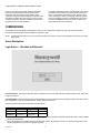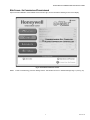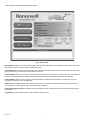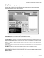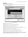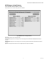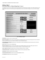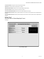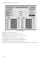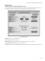
1
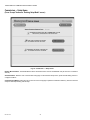
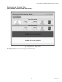
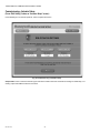
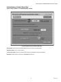
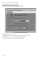
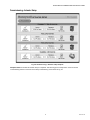
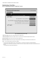
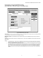
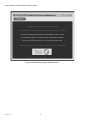
YP900A
Delphi Combustion Efficiency Panel
USER QUICK START GUIDE
SUPPORTING DOCUMENTATION
The software should only be used by experienced and /or
licensed burner/boiler operators and mechanics.
This document provides quick start guide information. Please
refer to other applicable publications for details:
— 66-1190, YP900A Installation Instructions
— 65-0084, Q7800A 22 Terminal Wiring Subbase
Product Data
— 66-1162, RM7840L1075 Relay Module with Valve
Proving Installation Instructions
— 65-0029, 7800 Series Relay Module Checkout and
Test
— 65-0288, S7800A1142 Keyboard Display Module
Product Data
— 65-0089, ST7800 Plug-in Purge Timer
— 60-2026, C7027, C7035, C7044, C7927 Minipeeper
UV Flame Detector
— 65-0267, C7961 Dynamic Self-checking Solid State
UV Flame Detector
— 60-0292, C7915 Infrared Flame Detector
— 65-0277, C7962 Visible Light Flame Detector
— 60-2024, C7007, C7008, C7009 Flame Rod Detector
— 95-8269, C7076 Adjustable Sensitivity UV Flame
Detector
— 60-2398, C7012 Ultraviolet Flame Detectors
— 50030542-1-EN, MF020 Oxygen Sensor Installation
Instructions
— 000670-1-EN, MF010 and MF020 Series Oxygen
Sensors
— 51-52-03-31, HC900 (ABC900) Hybrid Controller
Specification sheet
— 009558-1-EN, SNDJ-CNT Series Tachometers
— 005886-2-EN, LCZ Series Hall-effect Zero Speed
Sensors
— 65-0264 ML7999B Direct Coupled Actuator
— 63-2600 NXS VFD User Manual and Application
Manual
— 62-86-25-10 Operation Manual for HercuLine
2001-100/200/400-090-EC actuator
— 62-86-24-14 Quick Start Guide for HercuLine
2001-100/200/400-090-EC actuator
— 62-86-33-48 Instruction Sheet for V51E valve mounting kits 51452354-513/514EC
Read all documentation carefully and respond appropriately to
all error messages.
SAFETY NOTES
WARNING
Explosion Hazard.
Improper configuration can cause fuel buildup and
explosion.
Operators of this software may move fuel and/or air
actuators to positions that can create hazardous
burner conditions. Improper user operation may result
in property loss, physical injury or death.
When installing this product...
1.
2.
3.
4.
Read these instructions carefully. Failure to follow them
could damage the product or cause a hazardous condition.
Check the ratings given in the instructions and marked
on the product to make sure the product is suitable for
the application.
Installer must be a trained, experienced flame safeguard service technician.
After installation is complete, check out the product
operation as provided in these instructions.
INTRODUCTION
The Honeywell Delphi YP900A Combustion Efficiency Panel
is a loop-and-logic-based integrated flame safeguard control
and fuel-air ratio control with O2 Trim capability for burner and
boiler applications.
The Delphi YP900A Combustion Efficiency Panel is a
completed panel assembly which consists of RM7840L1075
burner safety controller with wiring subbase and S7800A1142
Keyboard Display module, built-in industrial panel PC with
touchscreen display and a ABC900A loop-and-logic controller
for load and O2 trim control. Also included in the YP900A
Combustion Efficiency Panel assembly are O2 Sensor with
mounting accessories and Hall-effect speed sensor with
tachometer.
The system software incorporates many features that are
designed to guide you safely through the commissioning
process. Safety, however, is your responsibility.
66-1191-02
YP900A DELPHI COMBUSTION EFFICIENCY PANEL
The Display, ABC900A controller, and RM7840L burner safety
controller all communicate to provide accurate control and
time in commissioning and runtime modes. During runtime
mode, the display is used for monitoring, shutdown, manual
control, and setpoint changes. The ABC900A loop and logic
controller and RM7840L1075 burner safety controller are
responsible for the runtime operation.
Functions provided by the Delphi YP900A Combustion
Efficiency Panel assembly include automatic burner
sequencing with VPS (Valve Proving System), flame
supervision, status and system diagnostic indications. Also
included are Fuel/Air ratio control with O2 trim to provide
complete combustion and PID modulating load control for
firing rate plus low fire hold capability.
COMMISSIONING
The following screen descriptions are provided so that you can understand the purpose of each and view the selections,
parameters, and information that are available or required on each.
NOTE: Touching the main title bar on any screen (Honeywell logo on the top of each screen) will take user back to the “Home”
page screen.
Screen Descriptions:
Login Screen — Username and Password
Fig. 1. Login screen — Username and password.
Username Button: Touching the Username text-box will take the user to the Keyboard screen page where the user will be able
to type in Username.
Password Button: Touching the Password text-box will take the user to the Keyboard screen page where the user will be able to
type in Password. There are 3 password levels: Installer, Manager and User.
The factory default Username and Password are listed below.
Installer Level2 Manager Level2 User Level
Username
(see note 1)
(see note 1)
user
Password
1)
1)
pass
(see note
(see note
1
For security reasons, passwords for installer and manager levels are included in separate postcard-like caution cards included
with the panel assembly.
2 When commissioning is complete and/or the access level needs to be changed, the user must log out and sign back in with
the desired password access level for general operation.
66-1191—02
2
YP900A DELPHI COMBUSTION EFFICIENCY PANEL
Main Screen—Un-Commissioned/Commissioned
Upon successful installation of the YP900A and successful Login, the user will see the following screen on the display:
Fig. 2. Uncommissioned main screen.
NOTE: To start commissioning, press the “Settings” button. This will take the user to “Software Settings Page 1” (see Fig. 10).
3
66-1191—02
YP900A DELPHI COMBUSTION EFFICIENCY PANEL
Fig. 3. Main screen.
Monitor Button: Takes the user to the Monitor page where the user will be able to see an image of the burner/boiler, all relevant
data points as well as the current status of the burner controller.
Charts Button: Takes the user to the Charts Page. This is where the user will be able to view, on a chart, each of the curves built
during commissioning as well as the current position on the curve.
Lockouts Button: Takes the user to the Lockout Screen. This is where the user can see the current list of lockouts, including the
lockouts in the RM7840 Burner Controller as well as the Interlocks built into the ABC900 Advanced Burner Controller.
Settings Button: When the user is logged in as the INSTALLER, the Settings Button will appear. This takes the user to the
Setting and Commission area of the application.
System Alerts: The System Alerts area is located on most screens. In general, this area will inform the user why the burner is
not running due to a fault, hardware input, or a software limit or interlock.
Commissioning Not Complete: This displays when the YP900A is not yet commissioned. To start commissioning of the system,
press Settings.
Logoff Button: This button will log off the user and display the login screen.
66-1191—02
4
YP900A DELPHI COMBUSTION EFFICIENCY PANEL
Monitor Screen
(Press “Monitor” button on “Main” screen.)
The monitor display is intended to be the primary information screen. The user will be able to monitor the most important
parameters in the combustion efficiency system on this screen:
Fig. 4. Monitor screen.
Sequence State: Displays the current sequence state of the RM7840L Burner Controller.
Time in Current State: Displays the time in the current state of the RM7840L Burner Controller.
Firing Rate (PID Output): Displays the current Firing Rate. This is determined by the PID Loop in the ABC900 Controller. If the
remote control Process Variable is selected, the Firing Rate is driven direct from the Remote BMS or SCADA Process Variable
analog input to the ABC900.
Exhaust Air O2 Setpoint: O2 setpoint currently used to reset the air values during O2 Trim Control. This is displayed when O2
Trim is ENABLED.
Air Adjustment: The amount of adjustment made to the Air Damper and VFD during O2 Trim. This value is displayed when the
O2 Trim is ENABLED.
Manual Mode: Press this button to turn off Process Variable input and put system into Manual firing rate control.
Increment/Decrement Buttons: Will increase/decrease the firing rate value.
Process Variable: Displays the current value of the Process Variable. The units displayed are settings in the settings area of the
INSTALLER application.
Stack Temperature: Displays the current stack temperature. The units displayed are settings in the settings area of the
INSTALLER application.
5
66-1191—02
YP900A DELPHI COMBUSTION EFFICIENCY PANEL
O2 Transmitter: Displays the current Oxygen level in the Exhaust stack. This value is displayed when the O2 Transmitter is
ENABLED.
History Chart: Displays the short term history for the Process Variable, Firing Rate, Stack Temperature, Ambient Air
Temperature, Estimated Burner Efficiency, and O2 Level (if Enabled).
Clip Board icon Button: Press this button to make changes to Firing Rate Loop setpoint and Process Variable Max. Value.
Feedback Parameters (Fuel, VFD, Air Actuator, FGR): Displays the current FEEDBACK of the Air Actuator (if Enabled), VFD,
Fuel Valve Actuator, and FGR Actuator (if Enabled).
RM7840L LED Indicators (Power, Flame, Pilot, Main, Flame Signal): Displays the current status of the LEDs on the RM7840L
Burner Controller. The current Flame Signal Strength is also displayed here.
Alarms: Flashes when there is an unacknowledged alarm. It does not necessarily indicate a current alarm. Pressing this button
will take the user to the Alarm Acknowledgement screen on all screens except when commissioning. The Alarm flag will still
indicate an unacknowledged alarm, but pressing it will not leave the current screen.
System Alerts: The System Alerts area is located on most screens. In general, this area will inform the user why the burner is
not running due to a fault, hardware input, or a software limit or interlock.
Air Flow Switch: Indicates the status of the Air Flow Switch.
Modulate: Indicates the RM7840L and the ABC900 have released the burner to modulate.
Honeywell Logo: On most pages, this can be pressed to access the home page. It is not available in commissioning mode.
66-1191—02
6
YP900A DELPHI COMBUSTION EFFICIENCY PANEL
RM7840 Screen
(Press “RM7840” button on “Monitor” screen.)
Screen allows the user to view the RM7840 control parameters, including the current sequence state, flame signal, fault
information and troubleshooting for the specific fault:
Fig. 5. RM7840 screen.
Back Button: Takes the user to the previous page.
Sequence State: Displays the current sequence state of the RM7840L Burner Controller.
Fault Code: If the RM7840 is in a Fault condition, the fault code is displayed here.
Extended Description: Displays the extended description of the fault code.
Get Info: Takes the user to the troubleshooting information when the Burner Controller is in a Fault Condition.
System Alerts: The System Alerts area is located on most screens. In general, this area will inform the user why the burner is
not running due to a fault, hardware input, or a software limit or interlock.
Sequence Time: This displays the time in the current state of the RM7840L Burner Controller.
Flame Signal: Displays the current Flame Signal being sensed by the RM7840L and the associated scanner.
Fault History: Links to the active fault history specifically related to the RM7840L burner controller.
Alarms: Flashes when there is an unacknowledged alarm. It does not necessarily indicate a current alarm. Pressing this button
will take the user to the Alarm Acknowledgement screen on all screens except when commissioning. The Alarm flag will still
indicate an unacknowledged alarm, but pressing it will not leave the current screen.
7
66-1191—02
YP900A DELPHI COMBUSTION EFFICIENCY PANEL
Total Hours: Displays the total run hours of the RM7840L controller. This does not necessarily indicate the runtime of the Delphi
YP900A.
Total Cycles: Displays the total cycles of the RM7840L burner controller. This does not necessarily indicate the runtime of the
Delphi YP900A.
RM7840L LED Indicators (Power, Pilot Valve, Flame Sensed, Main Valve, Alarm): Displays the current status of the LEDs on
the RM7840L Burner Controller. The current Flame Signal Strength is also displayed here.
66-1191—02
8
YP900A DELPHI COMBUSTION EFFICIENCY PANEL
ABC900 Screens—Analog IO Summary
(Press “ABC900A” button on “Monitor” screen.)
Screen allows the user to view the Analog values in the ABC900:
Fig. 6. ABC900 screens—analog IO summary.
Back Button: Takes the user to the previous page.
Analog Inputs: Displays the current reading for each of the analog inputs associated with the ABC900 Advanced Burner
Controller.
Analog Outputs: Displays the current reading for each of the analog outputs associated with the ABC900 Advanced Burner
Controller.
Digital IO: Pressing this button takes the user to the Digital Inputs and Outputs of the ABC900.
9
66-1191—02
YP900A DELPHI COMBUSTION EFFICIENCY PANEL
ABC900 Screens—Digital IO Summary
(Press “Digital I/O” button on “ABC900A Analog I/O Summary” screen.)
Screen allows the user to view the Digital values in the ABC900:
Fig. 7. ABC900 screens—digital IO summary.
Back Button: Takes the user to the previous page.
Digital Inputs: Displays the current reading for each of the digital inputs associated with the ABC900 Advanced Burner
Controller.
Digital Outputs: Displays the current reading for each of the digital outputs associated with the ABC900 Advanced Burner
Controller.
66-1191—02
10
YP900A DELPHI COMBUSTION EFFICIENCY PANEL
Charting Screen
(Press “Curves” button on “Main” screen.)
The Charts screen displays the current curve as built during commissioning. Each curve can be reviewed individually by pressing
the button for the associated chart:
Fig. 8. Charting screen.
Back Button: Takes the user to the previous page.
Fuel 1 Curve: Displays the curves built during commissioning for Fuel 1. If VPS is enabled, Fuel 1 should always be fuel gas.
Fuel 2 Curve: Displays the curves built during commissioning for Fuel 2.
NOTE: To view current firing rate positions, press the “Refresh” button at top of this screen.
11
66-1191—02
YP900A DELPHI COMBUSTION EFFICIENCY PANEL
Lockout Screen
(Press “Lockout” button on “Main” screen.)
Displays the current lockouts and software alarms that have not been acknowledged. All lockouts must be cleared in order for the
burner controller to light:
Fig. 9. Lockout screen.
Back Button: Takes the user to the previous page.
Active Lockouts/Interlocks: Displays the current Lockouts. These must all be cleared for the RM7840L to begin its sequence.
Reset Area: Press the green button to reset all the lockouts. This will reset the lockouts for a period of 20 seconds. If the lockout
persists, please check the field hardware for malfunction.
NOTE: Touch “?” for additional information on Lockout or Alarm.
66-1191—02
12
YP900A DELPHI COMBUSTION EFFICIENCY PANEL
Settings—Page 1
(Press “Settings” button on “Main” screen.)
The Settings area is where the installer will setup all the parameters associated with the YP900A. This includes all setpoints, limit
and interlock names, and commissioning of the independent fuel curves.
NOTE: Complete all the setpoints/parameters setup pages using the “Next” and “Back” buttons. Please make sure
actuators are “Enabled.” Once all software settings pages have been completed, press the “Utilities” button to
continue commissioning steps.
Fig. 10. Settings—page 1.
Back Button: Takes the user to the previous page.
Next: Takes the user to the next Settings page.
Edit Units: Set the Process Variable units here. It can be “PSI” or “Deg F”.
Edit Display Names: Shortcut to the Settings Page 4 for quick access to editing the display names of the variables.
Utilities: Shortcut to the Control Panel Utilities screen for System Commissioning, Back-up and Display override.
Platform: Shortcut to screen for setting Time, Time Zone and IP.
Firing Rate Loop Setpoint: Setpoint used to control the firing rate via the process variable transmitter.
Increment/Decrement Buttons (1): This will increment / decrement the value by 1 with each press.
Increment/Decrement Buttons (10): This will increment / decrement the value by 10 with each press.
Process Variable Max. Value: This is the actual maximum setpoint for the Process Variable, as measured by the process
variable transmitter, used by the ABC900 to shutdown the burner. This breaks the limit circuit and shuts down the boiler. It will
restart once the process variable drops below the value of Process Variable Max minus Offset (differential) Value.
Low Fire Hold Setpoint: Upon start-up, the burner will remain in Low Fire until process variable exceeds this setpoint.
Low Fire Hold Firing Rate: The firing rate the ABC900 will remain at during Low Fire Hold.
Main Valve Modulation Delay: Delay time in seconds that the unit will remain in Low Fire before being release to Modulate. This
time is in ADDITION to the time built in the RM7840L burner controller.
13
66-1191—02
YP900A DELPHI COMBUSTION EFFICIENCY PANEL
Settings—Page 2
(Press “Next” button on “Software Settings Page 1” screen.)
The Settings area is where the installer will setup all the parameters associated with the YP900A. This includes all setpoints, limit
and interlock names, and commissioning of the independent fuel curves. Fuel selection/changes can only be made in standby
mode.
Fig. 11. Settings—page 2.
Back Button: Takes the user to the previous page.
Minimum VFD Speed: Set the minimum speed setting for the Variable Frequency Drive. When setting up the VFD, the minimum
frequency should be set to 0 Hz to allow the variable to control the Minimum speed.
Increment/Decrement Buttons: Will increment / decrement the value by a predetermined value with each press. This value
cannot be modified.
Next: Takes the user to the next Settings page.
Maximum VFD Speed: Set the maximum speed setting for the Variable Frequency Drive. When setting up the VFD, the
maximum frequency should be set to 60 Hz to allow the variable to control the Maximum speed.
Stack Temperature Sensor: Indicates whether the stack temperature sensor is enabled.
Enable/Disable Button: Enable/Disable the stack temperature sensor by pressing this button.
VFD Enable: Indicates whether the VFD is enabled.
VFD Enable/Disable Button: Allows the user to Enable/Disable the VFD.
Fuel Selection: Displays the current Fuel selection.
66-1191—02
14
YP900A DELPHI COMBUSTION EFFICIENCY PANEL
Fuel Selection Button: Change the active Fuel by pressing this button.
FGR Enabled: Indicates whether the FGR actuator is enabled.
FGR Enable/Disable Button: Allows the user to Enable / Disable the FGR Actuator.
Air Actuator Enabled: Indicates whether the Air Actuator is enabled.
Air Actuator Enable/Disable Button: Allows the user to Enable / Disable the Air Actuator.
Air Actuator Minimum Position: Minimum position allowed for the Air Actuator. Press the up/down arrows to adjust between 0
and 100%.
Air Actuator Maximum Position: Maximum position allowed for the Air Actuator. Press the up/down arrows to adjust between 0
and 100%.
Settings—Page 3
(Press “Next” button on “Software Settings Page 2” screen.)
O2 Settings
Fig. 12. Settings—page 3.
15
66-1191—02
YP900A DELPHI COMBUSTION EFFICIENCY PANEL
Fig. 13. Settings—page 3.
Back Button: Takes the user to the previous page.
Oxygen Sensor: Indicates whether the Oxygen sensor is enabled.
Enable/Disable Button: Enable/Disable the Oxygen sensor by pressing this button.
O2 Trim: Indicates whether the O2 Trim is enabled.
Enable/Disable Button: Enable/Disable the O2 Trim by pressing this button.
O2 Setpoint Strategy: Indicates whether the O2 Setpoint Strategy is Basic or Multi.
Basic/Advance Button: Select Basic or Advanced for the O2 Setpoint Strategy.
O2 Setpoint: Set the O2 Setpoint to be used at each point in the Firing Rate. The setpoint will remain constant between steps.
66-1191—02
16
YP900A DELPHI COMBUSTION EFFICIENCY PANEL
Settings—Page 4
(Press “Next” button on “Software Settings Page 3” screen.)
The Settings area is where the installer will setup all the parameters associated with the YP900A Combustion Efficiency Panel.
This includes all setpoints, limit and interlock names, and commissioning of the independent fuel curves.
Fig. 14. Settings—page 4.
Back Button: Takes the user to the previous page.
Next: Takes the user to the next Settings page.
Stack Temp Max Value: The actual setpoint used by the ABC900 to shutdown the burner (if enabled).
Increment/Decrement Buttons: Will increment / decrement the value.
Auto-Tuning: Allows the user to enable/disable auto-tuning function (See Installation Instructions, form #66-1190 for details.)
17
66-1191—02
YP900A DELPHI COMBUSTION EFFICIENCY PANEL
Settings—Page 5
(Press “Next” button on “Software Settings Page 4” screen.)
PID Load Control setting
Fig. 15. Settings—page 5.
Proportional Band (Gain): Allows for adjusting the load control's Proportional Band setting
Integral (Reset): Allows for adjusting the load control's Integral action setting
Derivative (Rate): Allows for adjusting the load control's Derivative action setting
NOTE: Default PID settings are as follows:
P = 15
I = 1.46
D = 0
Fine tune or change if necessary.
66-1191—02
18
YP900A DELPHI COMBUSTION EFFICIENCY PANEL
Settings—Page 6
(Press “Next” button on “Software Settings Page 5” screen.)
Analog Inputs
Fig. 16. Settings—page 6.
Back Button: Takes the user to the previous page.
Display Names: The name displayed on the user interface for the variable.
Setup: Press this button to setup the Process Variable. Selection items include temperature/pressure/remote and process
variable range low and high (temperature or pressure) for the transmitter scaling.
Edit Name: Edit the display name for each input. Changing the name does not modify the application, nor does it affect the
control strategy. On the next screen after pressing the “Edit Name” button, touch the existing name text box to bring up the
keyboard screen.
19
66-1191—02
YP900A DELPHI COMBUSTION EFFICIENCY PANEL
Settings—Page 7
(Press “Next” button on “Software Settings Page 6” screen.)
Analog Inputs
Fig. 17. Settings—page 7.
Back Button: Takes the user to the previous page.
Display Names: The name displayed on the user interface for the variable.
Edit Name: Edit the display name for each input. Changing the name does not modify the application, nor does it affect the
control strategy.
66-1191—02
20
YP900A DELPHI COMBUSTION EFFICIENCY PANEL
Settings—Page 8
(Press “Next” button on “Software Settings Page 7” screen.)
Digital Inputs 1-8
Fig. 18. Settings—page 8.
Back Button: Takes the user to the previous page.
Display Names: The name displayed on the user interface for the variable.
Edit Name: Edit the display name for each input. Changing the name does not modify the application, nor does it affect the
control strategy.
21
66-1191—02
YP900A DELPHI COMBUSTION EFFICIENCY PANEL
Settings—Page 9
(Press “Next” button on “Software Settings Page 8” screen.)
Digital Inputs 9-16
Fig. 19. Settings—page 9.
Back Button: Takes the user to the previous page.
Display Names: The name displayed on the user interface for the variable.
Edit Name: Edit the display name for each input. Changing the name does not modify the application, nor does it affect the
control strategy.
66-1191—02
22
YP900A DELPHI COMBUSTION EFFICIENCY PANEL
Settings—Page 10
(Press “Next” button on “Software Settings Page 9” screen.)
Digital Outputs
Fig. 20. Settings—page 10.
Back Button: Takes the user to the previous page.
Display Names: The name displayed on the user interface for the variable.
Edit Name: Edit the display name for each input. Changing the name does not modify the application, nor does it affect the
control strategy.
NOTE: After completion of all Software Settings pages, go back to page 1 of Software Settings Page 1 (refer to Fig. 10) by
either pressing the “Back” button several times or by pressing the main title bar (Honeywell logo) and then “Settings”.
23
66-1191—02
YP900A DELPHI COMBUSTION EFFICIENCY PANEL
Utilities Screen
(Press “Utilities” button on “Software Settings Page 1” screen.)
The Control Panel Utilities screen allows for System Commissioning, backup of Configuration Settings and Display override.
Fig. 21. Utilities screen.
Commission Button: Press this button to setup the controller.
Save Settings Button: Press this button to save the user selected configuration settings, including fuel curves on the PC
directory.
Upgrade Button: Press this button to upgrade the modules (“JAR” software file) on the display. Please make sure the USB drive
with the upgrade modules (software file) is inserted in the back of the display to proceed. Upgrade only if there is a new
software version made available by Honeywell.
Restore Button: Press this button to restore the configuration on the display to the saved settings. This will overwrite all current
settings. This feature requires a USB drive, inserted into any available panel PC slot. On the drive, the folders created for the
Backup should exist, with the copied Delphi file. The system must be in Standby with the door switch in the off position to Restore
settings. When complete, log back into the system and return to the home page. Remove the USB drive from the slot. The
system will default to an uncommissioned state. The user must complete the commissioning process, including verification of all
11 fuel/air ratio curve steps, to make the system operable.
Backup Button: Press this button to save and backup the configuration database to a USB drive. This feature requires a USB
drive, inserted into any available panel PC slot. On the drive, create the following folders, which are case sensitive; Delphi/
backup. The system must be in Standby with the door switch in the off position to Backup the database. When complete, return
to the home page and remove the USB drive from the slot.
Reboot Button: Press this button to reboot the display if the screen has stopped functioning normally.
NOTE: The display can be shutdown and hard reboot by pushing the button located on the bottom of the PC display (on the
back side of the panel door).
66-1191—02
24
YP900A DELPHI COMBUSTION EFFICIENCY PANEL
Commission — Setup Warning
(Press “Commission” button on “Utilities” screen.)
Changes made in the Setup are critical and permanent. Only trained personnel should proceed with the setup operations.
Fig. 22. Commission — Setup Warning.
NOTE: Before pressing “Accept” and entering setup mode, please make sure to complete all the setpoints/parameters setup
with actuators “Enabled.” Press the “Back” button to go back to “Software Settings Page 1” (see Fig. 10) to complete the
setpoints/parameters setup and enable actuators.
25
66-1191—02
YP900A DELPHI COMBUSTION EFFICIENCY PANEL
Commission — Setup Home
(Press “Accept” button on “Entering Setup Mode” screen.)
Fig. 23. Commission — Setup Home.
Disable Burner Button: The Disable Burner button will break the limit circuit of the RM7840L and put the burner controller in
Standby.
Actuator Button: Takes the user to the Actuator setup page. On the Actuator Setup screen, press the Edit Setting. button to
configure actuators.
Commissioning Button: Takes the user to the Fuel Curve setup page to optimize Combustion Efficiency. Actuators must be
setup first before proceeding with this step.
66-1191—02
26
YP900A DELPHI COMBUSTION EFFICIENCY PANEL
Commissioning — Actuator Setup
(Press “Actuators” button on “Setup Home” screen.)
Fig. 24. Commission — Setup Home.
Edit Settings Button: Allows user to configure each enabled actuator.
27
66-1191—02
YP900A DELPHI COMBUSTION EFFICIENCY PANEL
Commissioning—Actuator Setup
(Press “Edit Setting” button on “Actuator Setup” screen.)
Use Edit Settings to set actuator positions. Press Complete when done.
Fig. 25. Commissioning—Actuator setup.
Setup button: Press to select the actuator types and set the actuator minimum and maximum settings for initial setup, or if
existing output and feedback values do not match.
66-1191—02
28
YP900A DELPHI COMBUSTION EFFICIENCY PANEL
Commissioning—Actuator Setup: Step 1
(Press “Setup” button on “Air Actuator Setup” screen.)
Fig. 26. Commissioning—Actuator setup step 1.
Select button: Press to select either ML7999B or HercuLine actuator for the application.
Send 4mA button: Press to move actuator.
Lock Position button: Press to lock actuator after actuator and feedback values have stabilized.
Next button: After actuator is locked and “checkmark” indicator is on.
29
66-1191—02
YP900A DELPHI COMBUSTION EFFICIENCY PANEL
Commissioning—Actuator Setup: Step 2
(Press “Next” button on “Air Actuator Setup: Step 1” screen.)
Fig. 27. Commissioning—Actuator setup step 2.
Send 20mA button: Press to move actuator.
Lock Position button: Press to lock actuator after actuator and feedback values have stabilized.
Complete button: Press after actuator is locked and “checkmark” indicator is on.
NOTE: Repeat the same actuator setup procedures for all other actuators.
66-1191—02
30
YP900A DELPHI COMBUSTION EFFICIENCY PANEL
Commissioning—Actuator Setup
Fig. 28. Commissioning—Actuator setup complete.
Complete button: Press after all actuator setup is completed. This will bring up the “Setup Home” screen. Press the
“Commissioning” button to enter fuel curves setup commissioning screen. Refer to Fig. 23.
31
66-1191—02
YP900A DELPHI COMBUSTION EFFICIENCY PANEL
Commissioning—Curve Setup
(Press “Commissioning” button on “Setup Home” screen.)
Fig. 29. Commissioning—Curve setup.
* Edit Curve button: allows user to make changes to the existing curve.
* Reset Curve button: allows user to build a new curve. The old curve is deleted and replaced with this action.
Save Curve button: press to save current curve as the default curve.
Restore Curve button: allows user to ignore changes made to the existing curve and restore to the saved curve.
NOTE: Fuel 1 should always be Gas if VPS is enabled.
* The screen will be slightly different if this is an initial setup (i.e., the system has not been commissioned before):
— The “Edit Curve” button will be replaced by a “Build Curve” button. Select the “Build Curve” button to start the fuel air curve
process.
— The “Reset Curve” button will be blanked out.
66-1191—02
32
YP900A DELPHI COMBUSTION EFFICIENCY PANEL
Commissioning—Purge & Lightoff Position Setup
(Press “Build Curve” or “Edit Curve” button on “Curve Setup” screen.)
Fig. 30. Commissioning—Curve setup.
Cancel Button: The user may cancel commissioning at any time. Pressing this button will stop the burner immediately, reset all
unsaved parameters, and return the user to the settings home page.
Disable Burner Button: The Disable Burner button will break the limit circuit of the RM7840L and put the burner controller in
Standby.
Start Button: Starts the blower motor/VFD. A heating demand (i.e., call for heat to the RM7840L) must be present and all system
alerts cleared.
NOTES:
—
—
—
A heating demand (i.e., call for heat to the RM7890L) must be present to proceed with purge position configuration.
Be aware of any System Alerts that may appear in the lower box. The System Alerts indicate system status that may
need to be addressed before the system can proceed.
If an alarm should occur at any time during the commissioning process, the user must disable the burner by selecting
the "Disable Burner" button and back out of the commissioning screens to reset and acknowledge any applicable
alarms. To do so, press the "Alarms" button on the top right corner of the screen. For the Software and Hardware
Lockouts, refer to Fig. 9. Once the alarms are acknowledged and reset, the user may return to the commissioning
screens.
33
66-1191—02
YP900A DELPHI COMBUSTION EFFICIENCY PANEL
Fig. 31. Commissioning—purge position configuration screen.
Lock Position button: Press after all actuators and VFD have reached their stable full position and have been visually verified.
NOTES:
—
—
—
66-1191—02
Purging position is factory fixed to 100% open for Air Actuator, Max. Speed for VFD and 0% for FGR.
After all actuators and VFD have reached their full and stable position with feedback LEDs on, press the
“Lock Position” button.
The system will start purging.
34
YP900A DELPHI COMBUSTION EFFICIENCY PANEL
Fig. 32. Commissioning—purge position complete screen.
When purge is complete, press the “Next” button to proceed.
35
66-1191—02
YP900A DELPHI COMBUSTION EFFICIENCY PANEL
Fig. 33. Commissioning—purge confirmation screen.
66-1191—02
36
YP900A DELPHI COMBUSTION EFFICIENCY PANEL
Commissioning—Lightoff Position
Fig. 34. Commissioning—lightoff position screen showing Save Step button.
Purge & Lightoff Position Setup: At this point the burner has not lit and is awaiting Low Fire Proof.
Cancel Button: The user may cancel commissioning at any time. Pressing this button will stop the burner immediately, reset all
unsaved parameters, and return the user to the setting home page.
Position indicator: Displays the value of the current output to the specific device or actuator.
Increment/Decrement Buttons: Increase the servo/VFD positions by pressing these buttons.
System Alerts: The System Alerts area is located on most screens. In general, this area will inform the user why the burner is
not running due to a fault, hardware input, or a software limit or interlock.
Active Fuel Selection: Indicates the active fuel.
Feedback LEDs: Indicates that the Feedback matches the output to the servo/VFD.
Disable Burner: The Disable Burner button will break the limit circuit of the RM7840L and put the burner controller in Standby.
Status Area: Indicates the status of several items including current step, process variable, O2 level, stack temp, and flame
signal.
Save Step button: Press after lightoff positions for all channels have been set.
NOTE: Lightoff position cannot be set below those settings in the Software Settings page for Air Actuator and VFD.
37
66-1191—02
YP900A DELPHI COMBUSTION EFFICIENCY PANEL
Commissioning—Lightoff Position
Fig. 35. Commissioning—lightoff position screen showing Lightoff button.
Lightoff button: Press after lightoff position has been saved via the Save Step button. Pressing the Lightoff button will secure
the current positions of the servos and VFD. A visual confirmation is recommended prior to pressing this button.
66-1191—02
38
YP900A DELPHI COMBUSTION EFFICIENCY PANEL
Commissioning—Lightoff Position Confirmation
Fig. 36. Commissioning—lightoff position confirmation screen.
Confirm button: Press after lightoff position has been saved.
Proceed to Lightoff button: Press to move into actual burner lightoff.
39
66-1191—02
YP900A DELPHI COMBUSTION EFFICIENCY PANEL
Commissioning—Modulation—Curve Setup
Curve Setup: At this point the burner has lit. When the burner process variable has exceeded the low fire hold setpoint, the user
may proceed in building the curve. All Limits and Interlocks are in effect during commissioning.
Fig. 37. Commissioning—modulation—curve setup.
NOTE: Always allow actuators/VFD to stabilize at each step before proceeding to next step.
66-1191—02
40
YP900A DELPHI COMBUSTION EFFICIENCY PANEL
Fig. 38. Commissioning—modulation—curve setup.
Cancel Button: The user may cancel commissioning at any time. Pressing this button will stop the burner immediately reset all
unsaved parameters, and return the user to the setting home page.
Position indicator: Displays the value of the current output to the specific device or actuator.
Position Feedback: Displays the feedback value of the individual servo or VFD.
Increment/Decrement Buttons: Increase the servo/VFD positions by pressing these buttons.
Previous Step: Pressing this button moves back one step. This is only displayed when a previous step exists and a save is not
required.
Next Step: Pressing this button moves forward one step. This is only displayed when a next step exists and a save is not
required.
FGR Position: FGR Values are displayed when the FGR is enabled.
Disable Burner: The Disable Burner button will break the limit circuit of the RM7840L and put the burner controller in Standby.
System Alerts: The System Alerts area is located on most screens. In general, this area will inform the user why the burner is
not running due to a fault, hardware input, or a software limit or interlock.
NOTES:
—
Always allow actuators/VFD to stabilize at each step before pushing “Save” button and proceeding to next step.
—
Each modulation curve requires 10 steps to complete the setup (11 steps counting lightoff).
—
After the modulating curve is completely built, press the “Complete Commissioning” button.
Status Area: Indicates the status of several items including current step, process variable, O2 level, stack temp, and flame
signal.
Process Variable: Displays the current value of the process variable.
41
66-1191—02
YP900A DELPHI COMBUSTION EFFICIENCY PANEL
Alarms: Flashes when there is an unacknowledged alarm. It does not necessarily indicate a current alarm. Pressing this button
will take the user to the Alarm Acknowledgement screen on all screens except when commissioning. The Alarm flag will still
indicate an unacknowledged alarm, but pressing it will not leave the current screen.
Fig. 39. Commissioning—modulation—curve setup.
NOTE: After step #11 is finished, press “Complete Commissioning” button.
66-1191—02
42
YP900A DELPHI COMBUSTION EFFICIENCY PANEL
Commissioning—Curve Setup Complete
Fig. 40. Commissioning—curve setup complete.
Fuel 1 curve set up completed. Repeat the set up procedures for Fuel 2 and FGR if necessary.
43
66-1191—02
YP900A DELPHI COMBUSTION EFFICIENCY PANEL
Platform Setting
(Press “Platform” button on “Software Setting Page 1” screen.)
Fig. 41. Platform settings screen.
This screen allows the user to set Time, Time Zone and IP information.
Save button: Press to save platform settings.
NOTE: After completion of this step, press the main title bar (Honeywell logo) to go to the Main/Home screen (refer to Fig. 3).
Automation and Control Solutions
Honeywell International Inc.
Honeywell Limited-Honeywell Limitée
1985 Douglas Drive North
35 Dynamic Drive
Golden Valley, MN 55422
Toronto, Ontario M1V 4Z9
customer.honeywell.com
® U.S. Registered Trademark
© 2009 Honeywell International Inc.
66-1191—02 M.S. Rev. 09-09