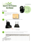
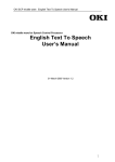
1
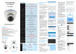
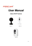
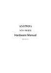
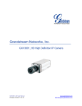
KEDACOM User Manual for HD IP Camera of IP Series Version 02 Trademark Kedacom™ and are trademarks of Suzhou Keda Technology Co., Ltd. in China and various other countries. All other trademarks mentioned in this document are the property of their respective holders. Suzhou Keda Technology Co., Ltd. 131 Jinshan Road New District, Suzhou, 215011 People's Republic of China http://www.kedacom.com/en Tel: +86-512-68418188 Fax: +86-512-68412699 © 2015 Suzhou Keda Technology Co., Ltd. All rights reserved. Without the prior written permission of Suzhou Keda Technology Co., Ltd., any reproduction, translation or retransmission of all or any part of this document for any purpose in either electronic or mechanical form is not allowed. Notice The information in this document is subject to change without notice. Every effort has been made in the preparation of this document to ensure accuracy of the contents, but all statements, information, and recommendations in this document do not constitute a warranty of any kind, express or implied. Suzhou Keda Technology Co., Ltd. is not responsible for printing or clerical errors. Target Audience Administrators and Operators of Video Surveillance Products Document Version Version 02 Applicable Models IPC113 and 123 series IPC185-AN series IPC2131 and 2231 series IPC2132 and 2232 series IPC2150 and 2250 series IPC2151 and 2251 series IPC2152 and 2252 series Related Document Quick Start Guide for IPC185-AN Quick Start Guide for IPC113 & IPC123 Quick Start Guide for IPC2131 2231 2132 2232 Quick Start Guide for IPC2150 2250 Quick Start Guide for IPC2151 2251 Quick Start Guide for IPC2152 2252 Convention Icon Sign B OLD > Convention Notes and warning: necessary supplement of operations Convention Menu, e.g. Drag to Zoom Connector between menus of different level, e.g. System Setting>Basic Setting CONTENTS 1. Product Brief ...........................................................................................................................................2 2. Appearance .............................................................................................................................................2 3. Start Up ....................................................................................................................................................4 3.1 Client Installation Conditions................................................................................................................................ 4 3.2 Initial Configuration .............................................................................................................................................. 4 3.2.1 Modify Parameter ......................................................................................................................................... 4 3.2.2 Login IPCCtrl .................................................................................................................................................. 5 3.2.3 Focus ............................................................................................................................................................. 6 4. Product Functions ..................................................................................................................................8 4.1 Live View ............................................................................................................................................................... 8 4.1.1 Toolbar Buttons ............................................................................................................................................. 8 4.1.2 Image Adjustment ......................................................................................................................................... 9 4.1.3 Auxiliary Function ........................................................................................................................................ 11 4.2 Motion Detection ............................................................................................................................................... 11 4.2.1 Set Area ....................................................................................................................................................... 11 4.2.2 Clear Area .................................................................................................................................................... 12 4.2.3 Disable Function .......................................................................................................................................... 12 4.3 Alarm Linkage ..................................................................................................................................................... 12 4.3.1 Motion Detection ........................................................................................................................................ 12 4.3.2 Parallel Port ................................................................................................................................................. 12 4.3.3 Alarm Recovery ........................................................................................................................................... 12 4.4 Privacy Mask ....................................................................................................................................................... 12 4.4.1 Set Area ....................................................................................................................................................... 12 4.4.2 Clear Area .................................................................................................................................................... 12 4.4.3 Disable Function .......................................................................................................................................... 12 4.5 Clipping Area Encode .......................................................................................................................................... 12 4.5.1 Set Area ....................................................................................................................................................... 13 4.5.2 Reset Area ................................................................................................................................................... 13 4.6 ROI Encode ......................................................................................................................................................... 13 4.6.1 Set Area ....................................................................................................................................................... 13 4.6.2 Reset Area ................................................................................................................................................... 13 4.7 Snapshot ............................................................................................................................................................. 13 4.8 Recording ............................................................................................................................................................ 13 4.8.1 Playback....................................................................................................................................................... 14 4.8.2 Download .................................................................................................................................................... 14 4.9 Auto Focus Triggered by Motion Detection ........................................................................................................ 14 4.10 Upgrade .............................................................................................................................................................. 15 4.10.1 Firmware Upgrade ....................................................................................................................................... 15 4.10.2 IPCCtrl Upgrade ........................................................................................................................................... 15 5. Parameter ..............................................................................................................................................16 5.1 Network Access .................................................................................................................................................. 16 5.1.1 Ethernet....................................................................................................................................................... 16 5.1.2 PPPoE........................................................................................................................................................... 16 5.2 Register to VMS .................................................................................................................................................. 16 5.3 BNC Output ........................................................................................................................................................ 17 5.4 User Management .............................................................................................................................................. 18 5.5 Text Overlay ........................................................................................................................................................ 18 5.6 Camera Mode ..................................................................................................................................................... 18 5.6.1 Configure Parameter......................................................................................................................................... 19 5.6.2 Import/Export Configuration ....................................................................................................................... 19 5.7 Dual-Stream ........................................................................................................................................................ 19 6. Appendix: Glossary of Terms ..............................................................................................................23 i HD IP Camera User Manual 2 1. Product Brief HD IP Camera (hereinafter referred to as Camera) is a remote video surveillance device based on IP network technology. It encodes and transmits HD video. Also, it can be deployed at any point of a surveillance network and transmits videos via public or private IP network. Main functions of the product: Live View Apply high-performance progressive scan sensor, with clear image and vivid color; High-performance video processing chip and efficient video encoding, providing HD video; Dual-stream to fit different network bandwidth; Configurable text overlay on video Alarm With audio and alarm connectors, realize functions of talkback and alarm; Motion detection and alarm linkage, make video surveillance intelligent; Support alarm linkage edit: Alarm Text Overlay, Device Output, Live View Display and etc. Networking Static address, DHCP or PPPoE; NAT traversal, DNS and multicast technology Memory With SD card slot, when the network breaks down, video can be stored in local SD card; Support local snapshot, default format is .JPG; Support local recording, user can query and playback recording on PC. 2. Appearance Picture 2-1 Box camera IPC113 and IPC123 series Picture 2-2 Box camera IPC185-AN series 2 HD IP Camera User Manual 3 Picture 2-3 Semi dome IPC2131, IPC2231, IPC2132, and IPC2232 series (with IR) Picture 2-4 Semi dome IPC2131, IPC2231, IPC2132, and IPC2232 series (without IR) Picture 2-5 IR Bullet Camera IPC2150 and 2250 series 3 HD IP Camera User Manual 4 Picture 2-6 IR bullet camera IPC2151 and 2251 series Picture 2-7 IR bullet camera IPC2152 and 2252 series 3. Start Up Please refer to the Quick Start Guide in the packing for device installation and wiring. 3.1 Client Installation Conditions Operating System: Windows XP or newer versions Browser: IE6.0 or newer versions Processor: 2.0 GHz CORE®2 series or other equivalent processors RAM Memory: 2GB or above DirectX:9.0c This manual will take IE7.0 as example. 3.2 Initial Configuration Power on camera after installation and wiring. 3.2.1 1) Modify Parameter Get IPCSearch from the attached CD. 4 HD IP Camera User Manual 5 Picture 3-1 IPCSearch Note: IPCSearch is green software free from installation. Camera name is subject to the search result. 2) Run IPCSearch: it will search devices in LAN automatically and display the list as shown in Picture3-1. 3) Select a camera to be configured, click in Picture 3-2. or right click the mouse. Interface is shown Picture 3-2 Modify Parameter 3.2.2 1) Login IPCCtrl After modification, will be disabled and the device will reboot automatically. Please wait patiently. After reboot, the button will be enabled again. Please select this device again and click or double click device name to enter web client. Interface is shown in Picture 3-3. 5 HD IP Camera 2) 3) User Manual 6 Picture 3-3 IPCCtrl Login Enter user name and password: IPCCtrl accounts consist of both admin and guest users: admin: can perform full operations. guest: can perform operations, for example, live video view, image search, video record search, video playback, etc. guest can neither configure parameters, delete videos or snapshots, nor operate user management or equipment maintenance. Interface after login is shown in Picture 3-4. Picture 3-4 IPCCtrl Interface 3.2.3 Focus It is the process of make the image of target object. Please focus according to the lens type of camera: Mechanical Focus: View live video on IPCCtrl and adjust the focus knob on the lenstill the image is clear enough. Electrical Focus: Click Or click under Focus in function buttons area of IPCCtrl, as the picture shows. for manual focus. View live video on IPCCtrl and adjust focus till the image is clear. 6 HD IP Camera User Manual 7 Picture 3-5 Electrical Focus 7 HD IP Camera User Manual 8 4. Product Functions IPCCtrl can not only view live video, but also perform local snapshot and recording, and set alarm linkage. Some models may not support some function below. User operation is subject to the actual functions of the model. Note: Disabled button in IPCCtrl means the model doesn‟t support the function. Function with * in this Manual means only some models support this function. 4.1 Live View The default interface after user login is live video view, or user can click Live View to enter the interface. 4.1.1 Toolbar Buttons Picture 4-1 Toolbar Buttons View Click this button to play live video. Stop Click this button to stop live view. Call / Click this button to call camera, and click again to stop calling. Not all cameras support this function. Listen / Click this button to listen to camera, and click again to stop listening. Not all cameras support this function, and the local PC should be equipped with audio output device. Full Screen Click this button to display full screen. When Drag to Zoom is disabled, double click the live video to display full screen directly, and double click again to exit. Snapshot / Click this button to snapshoot an image. Snapshot includes PU Snapshot Setting. and Local Snapshot . User can set in Parameter>Local Note: 1) PU Snapshot: PU Snapshots an image and sends it to local client in .JPG format. The image quality is good, but there is some time delay caused by network. 2) Local Snapshot: Client snapshots an image and save it locally. The image quality is ordinary, but there isn‟t any time delay. 8 HD IP Camera User Manual 9 Picture 4-2 Snapshot and Recording Configuration User can set or modify save path for PU Snapshot and Local Snapshot in Parameter>Local Setting, as shown in Picture 4-2. Recording / Click this button to start recording and click again to stop recording. Recording is saved on local PC. User can set or modify save path in Parameter>Local Setting. 4.1.2 Image Adjustment 4.1.2.1 Brightness Due to low light situation, the image will look completely or partially dark and hard to recognize. IPCCtrl provides the following functions to increase image brightness and ensure surveillance quality. *Enable IR Lamp In low light situation, IR lamp can be started to get better surveillance images. Increase Image Brightness In Image Adjustment part, user can drag Brightness slide bar to adjust image brightness. Or, enable Camera Mode to make camera transfer to preset value in a defined period of time. Slower Shutter Speed Camera shutter speed means the cycle of the sensor calculating light input amount. Therefore, the slower the speed is, the brighter the image is. Note: If the target object is moving fast, this method is not applicable. Set Max. Auto Shutter and Min. Auto Shutter in Parameter>Video Parameter>Basic Setting. Click (Manual) on Page 2 of function buttons to select shutter speed, measured in second (s). Increase Gain Camera gain means the light sensitivity of a sensor. A high gain may reduce light exposure for low light situation. Note: However, the higher the gain is, the worse the image will be. User is advised to select Auto, applying default values, or set Max. Auto Gain in Parameter>Video Parameter>Basic Setting. *Enable WDR WDR can provide optimal exposure in intense backlight conditions. On Page 2 of function buttons, click to enable WDR and to disable WDR. 9 HD IP Camera User Manual 10 For DN or EN series cameras (for example, the IPC123-EN), you need to enable WDR as follows: 1. Go to page 2 of function buttons. 2. Select Enable WDR from the Mode Select drop-down list. To disable WDR, select Close Mode from the Mode Select drop-down list. Note: You are advised to disable WDR if you use DN series cameras, for example, the IPC2131-DN-L and you want to employ a high encoding frame rate of 50 or 60 (Parameter > Video Parameter > Main Stream or Secondary Stream > Encoding Frame Rate). 4.1.2.2 White Balance Adjustment The basic conception of White Balance is “to make all colors white regardless of the color temperature of the light source”. It can compensate color rendition in pictures taken in specific light source. On Page 2 of function buttons, select White Balance Mode, Auto, Light or Manual. After selecting Manual, enter Red Gain and Blue Gain respectively to adjust image colors. 4.1.2.3 Day/Night Mode Day (Night) Mode means disabling (enabling) IR lamp (only some models support), and the image shifts to color (B/W), thus to get optimal images for day (sufficient light source) and night (insufficient light source) conditions. Day Mode On Page 1 of function buttons, click support) and the image shifts to color. Night Mode Click to B/W. Auto 4.1.2.4 (Day Mode) to disable IR lamp (only some models (Night Mode) to enable IR lamp (only some models support) and the image shifts Click (Auto) and the system will shift Day/Night Mode automatically according to pre-set value. Notes for different devices are as follows: Camera with IR lamp will shift to Day Mode or Night Mode automatically according to IR Sensitivity, which can be set on Page 4 of function buttons. Camera without IR lamp will shift to Day Mode or Night Mode automatically according to Color to B/W value and B/W to Color value, which can be set on Page 6 of function buttons. Also, user can enable Camera Mode to make camera shift to Night Mode automatically in a defined period of time. Noise Reduction When there are many noise points caused by environment and camera lens, Noise Reduction function can be enabled to adjust images. On Page 6 of function buttons, set Noise Reduction value and click 4.1.2.5 to save setting. Image Enhancement IPC121 series support Image Enhancement. User can adjust this parameter when the image is obscure. On Page 7 of function buttons, set enhancement value and click “Set” to save. 10 HD IP Camera 4.1.2.6 User Manual On Page 1 of function buttons, click restore to default values. 4.1.2.7 (All auto adjustments), and all parameters will Video Freeze On Page 5 of function buttons, select this function and the video will display the last frame image before clicking. Click 4.1.2.8 11 Auto Adjustment Auto Adjustment applies default settings of the camera block, which are suitable for most conditions. to disable freeze. Drag to Zoom Definition: Drag to Zoom function centers the selected area and zooms in the area to full screen. Enable:Right click the image and click Drag to Zoom on the popup menu to enable the function; or check Drag to Zoom on the bottom of Page 1 of function buttons. Start: Drag an area (left to right) with mouse to zoom in and center it. Cancel: Drag a reverse rectangle (right to left) with mouse to cancel zoom and center. Disable: Right click the image and click Drag to Zoom on the popup menu to disable the function; or uncheck Drag to Zoom on the bottom of Page 1 of function buttons. Picture 4-3 Drag to Zoom 4.1.3 Auxiliary Function *Defrost Some model supports defrost function. It is to start the heater for 30 minutes. User can enable or disable this function on Page 4 of function buttons. The heater will stop working automatically after 30 minutes. If the heater is started again during heating, it will keep on working for 30 minutes from this time. 4.2 Motion Detection Detect movements in the defined area. Once the movement exceeds the defined sensitivity, an alarm will be triggered by IPCCtrl. 4.2.1 1) Set Area Motion detection of Full Area and maximum 4 user-defined areas Check Parameter>Video Parameter>Intelligent Alarm to set motion detection area. 2) Check Enable Intelligent Alarm, and select Motion Detection. Detection area can be full area or specific area. If user selects specific area, the user should define detection area on the below image. 3) Click a square and it will turn purple red. Start from this square and draw an area to be the detection area, which will turn purple red. 4) Click under the view window or click to reset the area. 11 HD IP Camera User Manual 12 4.2.2 Clear Area Start from an undefined square and draw an area that contains the defined area, or click the defined squares one by one to clear setting. Save to make settings effective. 4.2.3 Disable Function To disable this function, uncheck the checkbox Enable Intelligent Alarm. 4.3 Alarm Linkage Alarm Linkage is the system reaction after an alarm signal is received. It is to raise watch man‟s attention to handle the event. The alarm signal comes from Motion Detection (details in Chapter 4.2) or Alarm Input Device (such as smoke detector) in the surveillance area. Alarm Linkage reaction includes Alarm Text Overlay, Snapshot or triggering alarm output device (such as alarm bell). 4.3.1 1) 2) Motion Detection Enable Motion Detection function and set detect area and sensitivity, details in Chapter 4.2. In Parameter>Snapshot Parameter, enable Motion Detection Snapshot, and set Snapshot Interval and Max. Snapshot Quantity. 4.3.2 Parallel Port Camera can be connected with switch signal devices. Make sure that alarm input device is normally open or closed and has been rightly connected to the alarm input port of camera. In Parameter>Snapshot Parameter interface, enable Alarm Triggered Snapshot, and set Snapshot Interval and Snapshot Quantity. In Parameter>Parallel Port Alarm>Parallel Port Alarm N (N is the input number) interface, enable Alarm Text and input text in Alarm Name. In Parameter>Parallel Port Alarm>Parallel Port Alarm N interface, set Alarm Output. In Parameter>Parallel Port Alarm>Parallel Port Alarm N interface, set alarm cycle in Alarm Input Type. 1) 2) 3) 4) 5) 4.3.3 Alarm Recovery Alarm Recovery means stop all reactions of the alarm linkage and return to normal view, such as cancel alarm text and alarm lamp flashing. In Parameter>System Setting>Basic Setting interface, set Alarm Recovery Time and save. For example, Alarm Recovery Time is set 60s, then all linkage reaction for next alarm (such as alarm text) will last for 60s. 4.4 Privacy Mask Mask sensitive and private part of the image so as to keep sensitive information private. 4.4.1 1) Set Area The image is divided into 16 columns and 12 rows of small squares. The maximum masking area can be 24 squares. The maximum number of Privacy Mask area is 4. Check Parameter>Video Parameter>Privacy Mask to set privacy mask area. 2) Check Enable Privacy Mask. 3) Click a square and it will turn purple red. Start from this square and draw an area to be the masking area, which will turn purple red. 4) Click under the view window or click to reset the area. 4.4.2 Clear Area Start from an undefined square and draw an area that contains the defined area, or click the defined squares one by one to clear setting. Save to make settings effective. 4.4.3 Disable Function To disable this function, uncheck the checkbox Enable Privacy Mask. 4.5 Clipping Area Encode After user defines the encoding area, the system will encode and display the clipping area only, so as to save system resources and network bandwidth. 12 HD IP Camera 4.5.1 User Manual 13 Set Area In the interface Parameter>Video Parameter>Clipping Area Encode, click area with mouse, click Area. 4.5.2 under the view window or click . Drag an to reset the areaReset Reset Area Click again to clear the old area and reset new area. 4.6 ROI Encode Only encode specific area to ensure normal surveillance and constant resolution of key area under poor network. The resolution of the area must be greater than 704×576 and less than the current resolution. 4.6.1 Set Area In the interface Parameter>Video Parameter>ROI Encode, click mouse, click 4.6.2 under the view window or click . Drag an area with to reset the area. Reset Area Click again to clear the old area and reset new area.. Note: When ROI Encode is enabled, if user modifies image resolution or aspect ratio (stand screen/widescreen), the device will quit ROI Encode automatically. 4.7 Snapshot Click to enter snapshot management interface. User can perform operations on snapshots in SD card, such as view, delete and download. Note: If the Snapshot interface is disabled, please confirm the SD card is inserted and then reboot client. Operation Steps 1) Search snapshots: search those pictures within the defined duration from the SD card. 2) On the snapshot list, select searched picture and perform operations such as view, delete and download. 4.8 Recording Click to enter recording management interface. User can perform operations on recordings in SD card, such as playback, delete and download. (A SD card must be inserted in the camera.) Note: If the Recording interface is disabled, please confirm the SD card is inserted and then reboot client. Note: Record Mode includes: Start Recording When Disconnected, Recording All the Time, and Stop Recording, configurable in Parameter>Recording Parameter. 13 HD IP Camera User Manual 14 Picture 4-4 Recording 4.9 4.8.1 1) 2) Playback Select Recording Duration from Calendar. If there is background color on a date, it means there is recording on that day. Select duration of the date and the video will be displayed directly in the right window. 4.8.2 Download Select Recording Duration from calendar and download recording to local PC, download path configurable. Auto Focus Triggered by Motion Detection The Auto Focus function can be triggered by the Motion Detection function. When the Motion Detection function detects a motion, an alarm is generated and the Auto Focus function is triggered. To achieve this, select the Motion Detection Trigger Auto Focus check box, as shown in Picture 4-5. Picture 4-5 Auto Focus Triggered by Motion Detection As shown in Picture 4-5, you can also configure the Auto Focus function to periodically operate. 14 HD IP Camera 4.10 User Manual 15 Upgrade 4.10.1 1) Firmware Upgrade Contact dealer for upgrade file. Method 1 Enter IPCCtrl interface Parameter>System Maintenance> Upgrade, as shown in Picture 4-6. Picture 4-6 Firmware Upgrade 2) Select local upgrade file (<*.pkg> or <*.img> format). 3) During upgrading, please do nothing but waiting. 4) After upgrading, please download ActiveX control again. After finishing it, reboot browser. Note: Please click “Upgrade” during system upgrading, and the upgrade file is usually in <*.pkg> or <*.img> format. 1) Method 2 Run IPCSearch. 2) Click to upgrade firmware of cameras of the same model simultaneously. 4.10.2 IPCCtrl Upgrade After firmware upgrade, please login web client again. The page will prompt to download a new ActiveX control. After downloading it, client upgrade will be completed. Login again to enter the latest IPCCtrl. Note: For detailed operation instructions of IPCCtrl, please refer to the help document. 15 HD IP Camera User Manual 16 5. Parameter Some models may not support some function below. User operation is subject to the actual functions of the model. 5.1 Network Access 5.1.1 Ethernet Open Parameter>Network Setting>Ethernet Parameter, as shown in Picture 5-1 to configure IP address, subnet mask and default gateway. Picture 5-1 Ethernet Parameter 5.1.2 PPPoE Open Parameter>Network Setting>PPPOEParameter, as shown in Picture 5-2 to enter user name and password, and save. Picture 5-2 PPPoE Parameter 5.2 Register to VMS Open Parameter>System Setting>Register to VMS as shown in Picture 5-3 to enter VMS address and port. Save settings and reboot device. 16 HD IP Camera User Manual 17 Picture 5-3 Register to VMS 5.3 BNC Output Camera with BNC output can output analog image directly when local display function is enabled. Open Parameter>Video Parameter>Camera Parameter, select „Start‟ from the BNC Output drop-down list and set the CVBS Video Mode, as shown below. Picture 5-4 BNC Output Note: For HD-SDI camera, when BNC output is started, the network will stop video output. 17 HD IP Camera User Manual 18 5.4 User Management Admin user has the authorization to modify passwords of IPCCtrl admin user and guest user. Modification method: 1) Open Parameter>System Setting>User Management 2) Check the checkbox of the item to be modified, the password area will be enabled and editable. 3) Enter new password. 4) Confirm new password. 5) Click Save to validate setting, and Reset to quit modification. 5.5 Text Overlay Display preset text on the surveillance window, configuration steps as follows: 1) Open Parameter>Video Parameter>Text Overlay, and click Edit Text, as shown in Picture 5-5. 2) Picture 5-5Text Overlay Check Edit Text checkbox to enable required OSD. Note: Different models may support different numbers of OSD. Configuration is subject to actual camera model. 3) 4) 5) Double click user-defined OSD to input text content. Each OSD supports maximally 3 lines of text. User can check Align Right checkbox to align texts on the right, or the default setting is “align left”. Drag text to the ideal position in the view window. Click Save to validate settings, and Reset to quit edit. Note: For IPC185-AN series, when enabling Quad Screen (refer to Picture 5-8), user can select different encoding channel to set different texts for them. Under this mode, time text can only display in the last channel that user sets. For example, user sets time for channels 1, 2 and 3 respectively, but time only display in channel 3 which is set last. 5.6 Camera Mode Open path: Parameter>Video Parameter>Camera Mode After enabling Camera Mode, user can define maximally 8 different non-overlapping durations, and all parameters will be adjusted to the preset values automatically. 18 HD IP Camera User Manual 19 5.6.1 Configure Parameter 5.6.1.1 Night Mode After enabling this function, device will shift to Night Mode in the defined duration automatically. The IR lamp will be enabled and the image will turn B/W. 5.6.1.2 Shutter, Gain, Auto Shutter and Gain values configurable Or enable Auto mode to apply set Shutter and Gain automatically. 5.6.1.3 Brightness, Contrast, Saturation, Sharpness Brightness, Contrast, Saturation and Sharpness values configurable Brightness, Contrast, Saturation and Sharpness range: 0-255. 5.6.1.4 Frame Rate, Encoding Rate Frame Rate and Encoding Rate configurable Picture 5-6 Camera Mode 5.6.2 Import/Export Configuration After completing configuration of camera mode, click click to export and save the configuration; to import local configuration file instead of manual configuration. 5.7 Dual-Stream Camera supports dual-stream encoding. Dual-stream means the same video source is encoded in 2 streams of video with different resolutions. User can select different resolution to view or record according to the bandwidth conditions. Open Parameter>Video Parameter>Main Stream Encode, as shown in Picture 5-7 to check Enable Sec. Stream checkbox. After enabling, user can configure secondary stream parameters in Parameter>Video Parameter>Secondary Stream Encode. 19 HD IP Camera User Manual 20 Picture 5-7 Main Stream Encoding IPC185-AN series support 4-channel encoding, resolution of each channel being 1080P. Go to Parameter>Video Parameter>Main Stream Encoding as Picture 5-8 shows, and select Quad Screen from the drop-down list of Enable Sec. Stream. Configure parameters and save, and reboot client to make settings effective. By back-end decoders, such as NVR or video wall, the 4-channel streams can constitute a complete image of HD 4K under Quad Screen mode. Among the 4 streams, the upper left one is the main stream, and the upper right, lower left and lower right are secondary 1, 2, 3 respectively. In Live View>Encoding Channel, user can switch channels to view, as Picture 5-9 shows. Under Quad Screen mode, camera function limitations are as follows: 1) Not support TF card-related functions (including alarm snapshot, ordinary TF card recording, and alarm TF card recording). 2) Not support Motion Detection. 3) Not support Privacy Mask. 4) Not support Clipping Area Encode. 5) Not support ROI. 6) When enabling snapshot function through client, only capture image of current channel, and support local snapshot only, PU snapshot not supported. 7) When enabling recording function through client, only record video of current channel. 8) Not support functions related with Image Flip. 20 HD IP Camera User Manual 21 Picture 5-8 Main Stream Encoding Note: After switching from single stream or dual-stream to quad screen mode, the code rate of 4-channel streams is updated to 4M simultaneously (user can modify it after login); after switching from quad screen to single stream or dual-stream mode, the main stream code rate is updated to 8M and the secondary stream code rate 1M simultaneously, resolution of main stream being 4096*2160 (user can modify it after login). Maximum capacity of single stream and multiple-stream is shown below: 4096×2160@23fps; Maximum Capacity of Single Stream 3840×2160@25fps; 2816×2112@30fps; 1920×1080@30fps. 4096×2160@22fps+D1 22fps; Maximum Capacity of Multiple-stream 3840×2160@24fps+D1 24fps; 2816×2112@30fps+D1 30fps; 1920×1080@30fps+D1 30fps. 21 HD IP Camera User Manual 22 Picture 5-9 Select Encoding Channel 22 6. Appendix: Glossary of Terms 1080p Resolution of 1920*1080 pixels (16:9) 720p Resolution of 1280*720 pixels (16:9) HD High-definition NAT Network Address Translation DHCP Dynamic Host Configuration Protocol DDNS Dynamic Domain Name Server IP Internet Protocol MPEG4 Moving Pictures Experts Group CIF Resolution of 352*288 pixels QCIF Resolution of 176*144 pixels QXGA Resolution of 2048*1536 pixels (4:3) UXGA Resolution of 1600*1200 pixels (4:3) PC Personal Computer PPPoE Point to Point Protocol over Ethernet 23