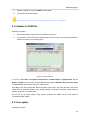
1
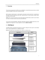
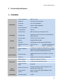
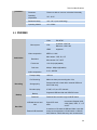
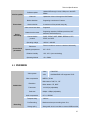
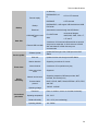
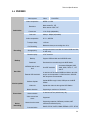
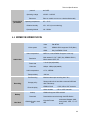
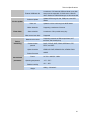
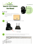
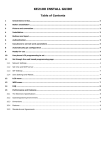
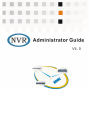
NVR Administrator Guide
Preface
Version
Software version: NVR4.02
About This Manual
Descriptor
Chapter Number
What is NVR?
Chapter 1
How to install NVR?
Chapter 2
Use it
Chapter 3~7
The Client——NVR Station
Chapter 8
Reset and Update
Chapter 9
Setting NAT/Proxy Server/Firewall
Technical Specifications
Appendix 1~4
Appendix 5
Related Manuals
NVR User Manual/NVR Quick Reference
NVR2820L Quick Reference
KDM201-D01H User Manual
KDM201S Multi-port Encoder Quick Reference
Lithium battery safety
A CR2032 Lithium battery is used in the NVR, please confirm the type to
avoid bombing when replaced. Don’t throw it into fire or garbage, you should
ask relative institutions for nearest recycle bin.
We try to insure the information is correct and the document will update with the software without notice,
please ask for your provider to access the document up to date.
Table of Contents
1
Overview ........................................................................................................................................... 1
1.1
NVR Model ......................................................................................................................... 1
1.2
KDM201S ........................................................................................................................... 2
1.3
Main Features ..................................................................................................................... 2
1.4
NVR Panels ........................................................................................................................ 5
1.5
2
3
1.4.1
NVR2820L Front Panel................................................................................................ 5
1.4.2
NVR2820 Front Panel ................................................................................................. 5
1.4.3
NVR2820E Front Panel ............................................................................................... 6
1.4.4
NVR2860 Front Panel ................................................................................................. 6
1.4.5
NVR2820L Rear Panel ................................................................................................ 7
1.4.6
NVR2820 Rear Panel .................................................................................................. 7
1.4.7
NVR2820E Rear Panel ................................................................................................ 7
1.4.8
NVR2860 Rear Panel .................................................................................................. 8
KDM201S Panels ............................................................................................................... 8
1.5.1
KDM201S Front Panel ................................................................................................. 9
1.5.2
KDM201S Rear Panel ................................................................................................. 9
1.5.3
KDM201S-C04E Encoder module ............................................................................. 10
1.5.4
KDM201S-D04 Decoder module ............................................................................... 11
1.5.5
KDM201-D01H HD Decoder module ......................................................................... 11
1.5.6
Inserting a module ..................................................................................................... 12
NVR Installation Guide .................................................................................................................... 13
2.1
Working Environment ....................................................................................................... 13
2.2
Installation steps ............................................................................................................... 13
2.3
Necessary Device Components........................................................................................ 14
2.4
Installing Built-in Hard disk ............................................................................................... 16
2.5
Configuration wizard ......................................................................................................... 20
2.5.1
NVR2820L ................................................................................................................. 20
2.5.2
Other NVR ................................................................................................................. 21
2.6
Configuring Video Source Device ..................................................................................... 22
2.7
Connecting Cables ........................................................................................................... 23
2.8
Verification ........................................................................................................................ 26
Network Configuration .................................................................................................................... 27
3.1
LAN Settings ..................................................................................................................... 27
i
3.2
Dial-up Network Settings .................................................................................................. 28
3.2.1
4
3.3
System service ................................................................................................................. 28
3.4
NAT Traversal Settings ..................................................................................................... 29
3.5
Proxy Settings .................................................................................................................. 30
3.6
Domain Name Service Settings ........................................................................................ 30
Video device Management.............................................................................................................. 31
4.1
Automatic Networking ....................................................................................................... 31
4.2
Add Video device .............................................................................................................. 31
4.3
Video device management ............................................................................................... 32
4.4
4.5
5
Dynamic Domain Name Server (DDNS) .................................................................... 28
4.3.1
Modify Registration Address ...................................................................................... 32
4.3.2
Replace a Device ...................................................................................................... 32
4.3.3
Device group ............................................................................................................. 32
Parameter Settings ........................................................................................................... 33
4.4.1
General ...................................................................................................................... 33
4.4.2
Audio ENC ................................................................................................................. 33
4.4.3
Video ENC ................................................................................................................. 33
4.4.4
Minor stream.............................................................................................................. 34
4.4.5
Motion Detection........................................................................................................ 34
4.4.6
Image Shade ............................................................................................................. 34
4.4.7
OSD ........................................................................................................................... 35
4.4.8
Camera ...................................................................................................................... 35
4.4.9
COM .......................................................................................................................... 35
4.4.10
Network Parameters .................................................................................................. 36
4.4.11
Dial-up Settings (validated after reset) ...................................................................... 36
4.4.12
Alarm Settings ........................................................................................................... 36
NVR register to Surveillance Platform .............................................................................. 37
Storage and Backup........................................................................................................................ 38
5.1
Disk Management ............................................................................................................. 38
5.2
Backup and Write in DVD ................................................................................................. 39
5.3
IP SAN .............................................................................................................................. 39
5.4
RAID5 ............................................................................................................................... 39
6
Alarm Device Management ............................................................................................................. 40
7
NVR Station .................................................................................................................................... 41
ii
8
7.1
Installation and Removal of Local Software ...................................................................... 41
7.2
WEB Access to NVR......................................................................................................... 41
7.3
Login ................................................................................................................................. 42
NVR Management .......................................................................................................................... 43
8.1
Recovering Factory Settings ............................................................................................. 43
8.2
Data Restoration ............................................................................................................... 43
8.3
Software Update ............................................................................................................... 43
8.3.1
U Disk Update ........................................................................................................... 43
8.3.2
Update via COM Port ................................................................................................ 44
8.3.3
Live update ................................................................................................................ 44
Appendix ................................................................................................................................................ 46
1
Registration Parameters Settings Other Than Multicast ................................................................. 46
2
NAT Settings ................................................................................................................................... 47
2.1
NVR Station Located in NAT ............................................................................................. 47
2.2
NVR Located in NAT ......................................................................................................... 47
2.2.1
NAT Settings of the LAN ............................................................................................ 48
2.2.2
NVR Settings ............................................................................................................. 48
2.2.3
NVR Station Settings ................................................................................................. 48
2.3
NVR and Station Located in Different NAT ....................................................................... 49
2.4
Camera and NVR Located in Different NAT...................................................................... 50
2.4.1
NAT Settings .............................................................................................................. 50
2.4.2
NVR Settings ............................................................................................................. 50
2.4.3
Camera (DVS) Settings ............................................................................................. 50
3
Settings of Proxy Server ................................................................................................................. 51
4
Firewall ........................................................................................................................................... 54
5
Technical Specifications .................................................................................................................. 55
5.1
NVR2820L ........................................................................................................................ 55
5.2
NVR2860 .......................................................................................................................... 56
5.3
NVR2820E ........................................................................................................................ 57
5.4
NVR2820 .......................................................................................................................... 59
5.5
KDM201S/ KDM201-D01H ............................................................................................... 60
Glossary ................................................................................................................................................. 62
iii
Overview
1 Overview
The document is appropriate for NVR series and KDM201S, and the NVR mentioned refers to all NVR
models and KDM201S except where otherwise indicated.
NVR is Network Video Recorder. It works together with network cameras and offers a comprehensive
surveillance solutions for detecting video motion, reporting alarms, live video viewing, recording, replay,
and camera control remotely.
KDM201S is a convergence multi-port encoder with storage accessed either by camera or by IP Camera,
and it offers surveillance solutions as the same with NVR series.
The document describes NVR2820L, NVR2820, NVR2820E, NVR2860 and KDM201S with focus on the
installation and configuration. For other operations, refer to the NVR User Manual.
1.1 NVR Model
The NVR models are quite different at appearance, interface, storage and video output. For more details,
refer to “Technical Specifications” in subsequent chapter.
Multiple NVR models are involved based on the number of surveillance sites:
Appearance
Models
NVR2820L
NVR2820-9
NVR2820-16
NVR2820-4D
NVR2820E-9
NVR2820E-16
NVR2820E-9D
NVR2820E-16D
NVR2860-32D
NVR2860-48D
NVR2860-64D
1
Overview
1.2 KDM201S
KDM201S is a convergence multi-port encoder, together with network cameras or cameras, offers a
comprehensive surveillance solution for video encoding, decoding, storage, video display, and control,
which can either organize network separately or register to surveillance platform.
Figure 1-1 KDM201S
1.3 Main Features
The NVR and KDM201S surveillance system run by means of establishing a dedicated surveillance
network or sharing with the service network, and the NVR Station help control surveillance system
through IP network. The typical network application is as shown in following figure.
Figure 1-2 Typical Networking
Live video view
1) multi-screen live view at the same time
2) multiple layout schemes
3) camera sequence and layout scheme sequence
4) PTZ control when viewing live video
Voice call
1) voice call and
voice record ,point to point, or broadcast to all sites
2) volume control, silent and mute
2
Overview
Recording and playback
1) triggered recording by: manual, schedule and alarm
2) Record management policy: including overwrite and backup policy
3) Records Management: including replay, query, backup, and delete
4) Records Replay: multi-video replay, synchronous replay and progress control
Storage management
1) Auto search and find the disk (built in or USB);
2) Manage the disk: make disk partition, format and record
ANR
Auto network replenishment, include records, snapshots and alarm logs, all of which can be restore to
the NVR when the network break down.
Management
1) User management, Log management, and storage management
2) Parameter setting: setting NVR parameters
3) Video unit management: adding, deletion and parameter configuration.
4) Version upgrade: by NVR Station, COM port and U disk
Alarm
1) Trigger alarm by alarm input (such as local alarm input, video motion detection, video loss), and
set the action to take , including buzzer sound, alarm output, recording, snapshot, PTZ rotation
to presets and caption) .
2) Alarm management: management of surveillance point and NVR alarms, event linkage policy
settings and alarm query
3) Alarm linkage: set the actions when an alarm occurs
Networking
1) Automatic networking
2) LAN, public network and hybrid network
3) NAT traversal and Socks5 proxy
4) Support different network providers
TV Wall
1) Camera sequence show on TV
2) maximum of 64 decoder( NVR2860 ) units to form a TV wall
3) 16 TV wall schemes
Control mode
1) independent control by remote control and USB mouse
3
Overview
2) NVR control by NVR Station
NVR Station
1) View simultaneous multiple videos, of the same or different NVR.
2) Records management
3) Video unit management
4) alarm management
5) NVR record and snapshot
6) A number of NVR management (16 at most)
7) multi-records replay synchronous of different NVR
8) TV wall configuration
9) Electric map function
Security
Perfect security solutions: user password, password attempt forbidden, IP filtering, user login encryption
Register to a surveillance platform
Register to KDM SP2 or KDM platform system
Other
1) Support SDK
2) Support Onvif encode device
4
Overview
1.4 NVR Panels
1.4.1 NVR2820L Front Panel
Figure 1-3 Front Panel of NVR2820L
1.4.2 NVR2820 Front Panel
Figure 1-4 Front Panel of NVR2820
5
Overview
1.4.3 NVR2820E Front Panel
Figure 1-5 Front Panel of NVR2820E
1.4.4 NVR2860 Front Panel
Figure 1-6 Front Panel of NVR2860
Notice: The ALARM LED blinks according to the alarm settings. Please refer to System Linkage in Chapter 5 of
NVR User Manual.
6
Overview
1.4.5 NVR2820L Rear Panel
Figure 1-7 Rear Panel of NVR2820L
1.4.6 NVR2820 Rear Panel
Figure 1-8 Rear Panel of NVR2820
1.4.7 NVR2820E Rear Panel
NVR2820E rear panel is similar with NVR2820, the following show the differences.
Figure 1-9 Rear Panel of NVR2820E-9, -16
7
Overview
Video Output mode: if the DIP switch is set to VGA, video output through the VGA interface; if set to
VIDEO, output through the TV interface. Select PAL or NTSL from the configuration interface.
Figure 1-10 Rear Panel of NVR2820E-9D, 16D
1.4.8 NVR2860 Rear Panel
Figure 1-11 Rear Panel of NVR2860
1.5 KDM201S Panels
KDM201S has eight boxes for hard disks in the front panel, and with eight slots in the rear panel for
inserting encoder or decoder panels.
8
Overview
1.5.1 KDM201S Front Panel
Figure 1-12 Front Panel of KDM201S
1.5.2 KDM201S Rear Panel
Figure 1-13 Rear Panel of KDM201S
If the VLAN dip is ON, all the modules can managed by the NVR; otherwise, they could be done by other
software in the network.
9
Overview
1.5.3 KDM201S-C04E Encoder module
Connect the interfaces with DB25 converter:
1, 4*BNC video in
2, 4*RCA audio in
3, 4*RCA audio out
5, 1*alarm out (switch)
6, 4*alarm in (switch)
7, running indicator
Model
KDM201S-C04E
Video Interface
4×BNC
Video Encoder
H.264
Resolution
D1、CIF、QCIF,DUAL STREAM
Frame Rate
1~25fps
Bit Rate
64Kbps~2Mbps
Audio In
4×RCA
Audio Out
4×RCA
Audio Protocol
ADPCM
Alarm In
4×SWITCH
Alarm Out
1×SWITCH
Control
4, 4*RS485
4×RS485
10
Overview
1.5.4 KDM201S-D04 Decoder module
Connect the interfaces with DB25 converter:
1, 4*BNC video out
2, 1*RCA audio in
Model
3, 1*RCA audio out
KDM201-D04
Video Interface
4×BNC
Video Decode
H.264、MPEG4
Resolution
D1、2CIF、CIF
Frame Rate
1~25 fps
Bit Rate
64Kbps~2Mbps
Audio In
1×RCA
Audio Out
1×RCA
Audio Protocol
4, Decoding indicator
G.711、ADPCM
1.5.5 KDM201-D01H HD Decoder module
1、DVI video out
2、BNC video out
3、3.5mm audio line out
4、3.5mm MIC audio out
5、RS232
6、USB
7、Reset
8、Decoding indicator
Please configure the D01H parameters in Client——IPCCtrl.
The detail parameters of D01H and the user manual of IPCCtrl, please refer to KDM201-D01H User
Manual and IPCCtrl Help.
11
Overview
1.5.6 Inserting a module
KDM201S has eight slots at the rear panel which is used for inserting modules, such as encoder and
decoder.
Clear the dusty on the stand before inserting a module, and take out the encoder or decoder module
from the anti-static package, then check the name on the module to confirm it is coordinate with the label
on the package.
Insert a module:
Push the module along the rail until it is blocked.
Fix the two screws besides the module.
Loosen the screws to take out the module.
Notice: Avoid touching the circuit and other components on the module while inserting the module.
12
NVR Installation Guide
2 NVR Installation Guide
The NVR must be put in a dry and well-ventilated environment with good dustproof, anti-interference and
lightning-protection capabilities.
2.1 Working Environment
Placement
Power
Place on a horizontal table or mounted on a rack.
Working voltage: 100V – 240V, frequency: 50 Hz – 60 Hz.
Alarm input: switch
Alarm Input/Output
Temperature
Alarm output: switch, normally open
Please pay attention to the type of the alarm input device. Refer to
Chapter 6 for details.
0℃~60℃
Humidity
10%~85%(non-condensing)
Altitude
-60~5000m
2.2 Installation steps
Following this flow to install the NVR surveillance system:
Section 0 describes necessary components, including
compulsory and optional units.
Step1
Preparation
components
Step 2
Install hard disk
Install the hard disk to store records.
Step3
Connect cables
Section 2.7, connect cables necessary.
Step4
configure network
Step 5
Manage the video unit
Step6
NVR Station access
Section chapter 3, set the network parameters according the
reality.
Section chapter 4,add device, modify, set parameters, etc.
Please refer to chapter 5 for disk management.
See chapter 7 for NVR Station.
13
NVR Installation Guide
2.3 Necessary Device Components
A user who buys a NVR device will have the following devices and components:
Icon
Name
NVR
Remote control
Audio/video cable
Network cable
Mouse
Green terminal
Remarks
Network Video Recorder
Conducts all operations related to the surveillance
system (applicable to NVR2820 and NVR2860)
Used for connecting audio/video unit
Used for connecting NVR and network
USB mouse
Two 6-pin and one 2-pin terminals, to connect
peripheral device.
Power cable
For connecting NVR and power supply
SATA cable
For connecting SATA hard disk
CD
User manual
Including: Software and user manuals
NVR Quick Reference,
NVR user Manual
14
NVR Installation Guide
The above devices are not enough for building a complete surveillance system. Based on the actual
needs, you have to prepare some additional devices, such as:
Icon
Name
Remarks
Video display device
Monitor, display or TV wall, at least one must be
selected
Video acquisition and
processing device
Combination of camera and encoder adapter or IPC
Surveillance keyboard
Optional, it can completely operate all functions.
Storage device
Rewriting device
Optional, hard disk, or USB disk array
Optional, USB DVD Rewriter
USB HUB
If multiple USB devices are to be connected at the
same time, the HUB can be used to expand the
number of USB interfaces. ZK-033 is recommended.
Audio device
Optional, audio in/out device: acoustics, microphone
or sound pickup
Alarm device
Optional, alarm input/output device: smoker sensor,
infrared probe, alarm ring, and so on.
15
NVR Installation Guide
2.4 Installing Built-in Hard disk
NVR2820L supports one built-in SATA hard disk.
Figure 2-1 Installing Hard disk for NVR2820L
Notice: If use the Seagate Barracuda LPTM 2TB hard disk, before the above steps, you need use the Jumper
block, the details as following.
Figure 2-2 Installing Jumper block in Hard disk for NVR2820L
16
NVR Installation Guide
NVR2820 supports one built-in IDE hard disk.
Figure 2-3 Installing Hard disk for NVR2820
17
NVR Installation Guide
The NVR2820E supports four or eight pieces of built-in SATA hard disks.
The installing method of supported four disks,
Figure 2-4 Installing Hard disk for NVR2820E
18
NVR Installation Guide
The installing method of NVR2820E which support eight disks is the same as above steps, but the hard
disk stand has two layer, you need tighten the 3 screws which in the bottom stand, the detail as the
following figure.
19
NVR Installation Guide
The NVR2860 and KDM201S support eight SATA hard disks.
Figure 2-5 Installing Hard disk for NVR2860 and KDM201S
2.5 Configuration wizard
Before building the surveillance environment, first conduct initial NVR configuration.
2.5.1 NVR2820L
According to the section “1.4 NVR Panels“, after all the cables connection. NVR2820L will automatically
start and it will automatically partition and format the built-in hard disk at first.
As NVR2820L has no local display output, its initial configuration need use IPCSearch which in the same
LAN to configure.
Default Parameters:
♦ IP Address:
♦ User
192.168.1.100
Name: admin
♦ Password:
admin123
20
NVR Installation Guide
Steps:
1) Run IPCSearch in the attached CD;
2) Select NVR with the default IP address in IPCSearch;
to modified the network parameters if necessary;
3) Click
4) After modified the parameters NVR2820L will restart and IPCSearch will re-find it, then double
click it or click
, you will login NVR Station——the NVR Client;
5) After login NVR Station, you need add IPC in surveillance list in the left side.
Notice:
1: The system requirement of PC which run NVR Station, please refer to Section “7 NVR Station”.
2: All the operation of NVR2820L need in the NVR Station, the function of NVR Station please refer to NVR Station Help, in
this document we’ll not repeat it.
2.5.2 Other NVR
Figure 2-6 Wiring of NVR2820 Wizard Configuration
After finish connecting cables, turn on the power and press the power switch power ON.
For first use, the Configuration Wizard interface opens automatically,
Alternately, from Main Menu Æ System Æ Wizard.
In the Wizard, you may configure:
♦ Network
♦ Hard
information
disk partition
♦ Networking
♦ Record
♦ Alarm
settings
Settings
settings
21
NVR Installation Guide
For initial configuration, it is recommended that network configuration be made first, and other settings
may be conducted after the buildup of the surveillance system.
Configuration information:
Parameter
NVR No.
System time
IP address
Subnet mask
Default GW
Description
If a number of NVR are used, please set the NVR No. from 0 to 8.When it is 8, the
NVR can be directly controlled by the remote control.
Set the time of the NVR.
Set the IP address of the NVR.
Set the subnet mask.
Set the gateway of the NVR.
In this condition, you check the box:
Enable auto
networking
NVR and video units are in the same LAN, and the number of video points does not
exceed 16 and there is only one NVR.
Thus, you implement auto networking without adding camera manually.
For a dial-up network or device placed in different LANs, you shouldn’t check it.
Refer to Chapter 3 for network configuration.
For a dial-up network or NVR with the use of DDNS, network information may not be set for the time
being. For detailed configurations, refer to related network configuration sections.
2.6 Configuring Video Source Device
The video unit, such as KDM2300 adapter, has initial network settings. For its availability in the
surveillance system, the network settings may be changed according to the actual network conditions.
For details, refer to the appendix.
22
NVR Installation Guide
2.7 Connecting Cables
Figure 2-7 Connect NVR cables
Figure 2-8 Connect KDM201S cables
23
NVR Installation Guide
Network Connection
Connect the NVR, camera and video unit to the network.
The illustrations show the method to make a network cable:
Connect Display/Monitor
Please select a display or monitor according to the network configurations to facilitate live video and
NVR parameter configuration.
Connect the blue VGA terminal on the rear panel to the display.
Connect the BNC connector on the rear panel to the monitor.
Acoustics/Loudspeaker Connection
Connect an acoustics or a speaker to the audio output connector.
Microphone Connection
Connect the audio in device, such as a microphone, to an audio input interface.
USB Device Connection
The NVR supports the following USB devices:
♦ USB
mouse
♦ USB
DVD rewriter
♦ USB
storage device
When multiple USB devices are to be connected, please use a USB hub, and ZK-033 is recommended.
24
NVR Installation Guide
Alarm Device Connection
The green terminal on the rear panel of the NVR can be used to connect alarm input/output device and
surveillance keyboard, which is same as the ALARM IN/OUT interfaces on the rear encoder of
KDM201S.
Pin outs of the green terminal:
Two pairs of alarm input pins: I1 and G, I2 and G.
Two pairs of alarm output pins: O1 and COM1, O2 and COM2
Connect the peripheral alarm device to the NVR, and the circuit diagram show the following:
DC power alarm in
AC power alarm in
The alarm output is a switch (non-voltage), external power is necessary to the alarm device. When the
power is DC, keep the voltage 12V (see the previous left figure). When the power is AC, a relay is
compulsive (see the previous right figure).
Surveillance Keyboard Connection
The surveillance keyboard KB10 is supported by NVR, which can control multiple NVR at different time.
Connect your keyboard to NVR by the RS485 connector, RS482A to connector 2, RS485B to 1, as
described in the illustration.
25
NVR Installation Guide
♦ Connect
a keyboard to multiple NVR:
♦ Connect
the keyboard to a NVR;
♦ Connect
all the NVR by RS485 connector, RS485A to RS485A, RS485B to RS485B.
See the NVR User Manual for surveillance keyboard operating details.
2.8 Verification
Switch on the power supply and turn on the device to enter the Configuration Wizard interface (refer to
NVR Quick Reference for details).
The NVR outputs VGA by default. When a TV set is connected, press
switch the output mode.
on your remote control to
26
Network Configuration
3 Network Configuration
The NVR supports deployment of diversified networks:
♦ LAN:
all devices are deployed over the same LAN.
♦ WAN:
all devices are deployed over the WAN (fixed IP or dial-up network), supporting DDNS.
Hybrid network: the NVR is deployed over an Intranet, while the NVR Station accesses via an Extranet,
supporting NAT traversal and Socks5 proxy.
Configure network from:
♦ Main
Menu Æ Wizard/Network Settings
♦ Main
Menu Æ Network
3.1 LAN Settings
NVR2820、NVR2820E and KDM201S have an ETH adapters. NVR2860 have two ETH adapters, please
confirm your connections before configure.
Parameter
IP address
Subnet mask
Description
The NVR may have several IP addresses. If it is over a public network, it is
recommended that the IP of the LAN be filled in as its first IP, and the
internet IP as the second one.
KDM201S have to configure two IP addresses. Fill in the internet IP address
as its first IP, and the LAN IP address as the second one which is DHCP
server IP address.
the subnet mask;
Default GW
the gateway address;
DNS Server
If the DDNS service is enabled for the NVR, fill in the available DNS IP over
the public network here;
SNTP Server
IP of the SNTP server;
Web Service Port
When the NVR Station access the NVR by domain name, the default port is
80, you can modify the port here.
NVR Station Connect
port
The default port is 1730, if changed, be sure to connect the right port by
NVR Station.
Local Port Receiving
NVR Station Detection
packets
When NVR Station is located in the NAT, please configure it.
Enable auto
After the auto networking is enabled, the video unit over the surveillance
network will automatically add to the NVR without manual adding.
27
Network Configuration
networking
Packet Lost Resend
Enable DHCP
After enabled, lost video packets will be retransmitted.
NVR worked as a DHCP server, and dispatch IP address to the video unit
which use DHCP
3.2 Dial-up Network Settings
Parameter
Enable PPPoE
Description
Enable dial-up function;
Dial-up username
Internet access username provided by the ISP;
Dial-up password
Internet access password provided by the ISP;
Auto dial-up
Auto dial-up after network disconnection. This check box is recommended
to be selected; otherwise you have to reset the NVR in case of network
disconnection;
waiting time
Waiting time for dial-up each time;
Retry times
The count of auto dial-up tries when failure connection.
If the NVR accesses to the surveillance network in form of domain name over a PPPoE network, the
DDNS service must be enabled, you need to set DDNS parameters.
3.2.1 Dynamic Domain Name Server (DDNS)
After proper setting of the PPPoE parameters, enter the DDNS Parameters interface from the NVR
Network Parameters interface:
1) Enable DDNS service(enter the DNS server first, Refer to DNS server parameters in Section
3.1 )
2) Configure DDNS server
3) Enter the passport and password
3.3 System service
Parameter
Enable auto
networking
Description
If this option is selected, the NVR search the device and add it automatically.
28
Network Configuration
Parameter
Description
The NVR worked as a DHCP server, and assign IP information to video units,
such as IPC, IPA, and decoder. See later calculating method for details. If
NVR2860 offer DHCP, the ETH1 connector must be used to connect to the
network.
DHCP
Packet lost Resend
If the option is selected, the lost packet will be resent to build good video
quality.
The synchronous time server.
SNTP server
The visitor connect NVR by domain name through the port that be defined
here.
Web service port
NVR Station
The default value is 1730, please connect the right port when modified.
Connection Port
NVR Station receive
Resend Port
The NVR Station receives the resend package through the port defined here.
Notice: DHCP IP address pool:
1: NVR2860 has two Ethernet cards, calculate the IP according the first IP address and subnet addresses both of
ETH0 and ETH1(1000M), to build two LAN.
2: To use DHCP server of NVR2860 need connect ETH1 (1000M), the way to use DHCP server of other NVR is
the same as “Notice 1”.
3: If the IP address of ETH0 or ETH1 and the default gateway are in the same LAN, the default gateway will affect
the ETH0 and ETH1.
3.4 NAT Traversal Settings
The NVR supports NAT traversal. The NAT traversal setting method is as follows:
Main Menu Æ Network Æ NAT
Select the check box NVR Located in NAT.
Parameter
NVR
Camera
Description
Local Port Receiving NVR Station
Detection Packets
The port for NVR Station to send packets to
traverse NAT
Local Port Receiving DVS Detection
Packets
DVS refers to encoder, IP Camera or other
devices to serve as encoder.
Camera
Select a video source;
The port for NVR to receiver video 1
NAT mapping port
Camera lay in different
29
Network Configuration
The port for NVR to receiver audio
NAT mapping port
The port for NVR to receiver video 2
NAT mapping port
NAT with NVR
Click advance to set the camera NAT parameters.
For NAT settings, refer to the NAT setting section in the appendix.
3.5 Proxy Settings
The NVR Station can access the NVR via Socks5 proxy. When the proxy function is enabled, Make sure:
Devices using proxy are not filtered by the proxy server;
The proxy service is available.
The NVR uses Socks5 proxy. Refer to the appendix for detailed proxy settings.
3.6 Domain Name Service Settings
The NVR supports access by domain name. Two cases are involved:
When the NVR uses a fixed IP, release the domain name, and the user may access the NVR with the
fixed IP or domain name;
When the NVR uses a dynamic IP, refer to Section 3.2.1 for domain name settings. The NVR Station can
only access the NVR with the domain name.
30
Video device Management
4 Video device Management
Video device means video encoder, IP Camera and decoder.
The NVR supports flexible networking, as well as auto and manual networking.
Notice: After networking, when you log on to the NVR Station to browse videos in local login mode, please make
sure that the smooth network connection between the visitor and the Encoder, for example, the configuration of such
information as route or gateway.
4.1 Automatic Networking
If there is only one NVR over the network and it is in the same LAN as all video units, after the auto
networking function is enabled, the user can implement auto networking without adding Manual.
Enable auto networking:
♦ Main
♦ Or
Menu Æ Settings Æ Network
Settings Æ Wizard/Network Settings
Select Enable Auto Networking on the open window.
Notice: Upon auto networking, please make sure that all devices involved are powered on and normally
connected to the network.
4.2 Add Video device
If the number of surveillance sites exceeds 16 and two or more NVR are deployed over the surveillance
network, please take the manual networking mode.
1) Select Main Menu Æ Devices or Wizard Æ Networking Æ Devices. An interface appears.
Click related functional button to enter related interface.
2) Click add device, and enter the IP information to conform;
3) Or click search device, and select the device in the list, then click add device in the open
windows.
After the device is added to the NVR, a camera ID is dispatched automatically which is unmodified, and
the ID indicate the relationship between the video and the monitor when a keyboard control the TV wall.
Notice: If the video device cannot be found but the device is online actually, check the address of the platform
which the video unit is added to is correct. Please refer to the appendix for the video device registration address.
31
Video device Management
See section “Appendix 1” for network access of devices other than multicast devices.
4.3 Video device management
Enter into the device management interface from the main menu, and select the device:
♦ Delete
device
♦ Change
device
♦ Change
name
♦ Monitor
status
♦ Restart
device
♦ Configuration
settings
Notice: please operate the video device when it is online. You are suggested to change device instead of delete.
4.3.1 Modify Registration Address
You can change the address of a registered device (except the internal device), conduct the following
operations:
1) Enter the interface for adding devices;
2) Select the device from the devices list;
3) Click Modify Address on the lower part of the interface;
4) Enter the address of the registered surveillance platform again or directly register to the current
NVR platform on the open interface.
4.3.2 Replace a Device
The internal devices can be replaced online instead of delete. Replace device B with A:
Enter into add device interface, and select device A in the list, then click change device;
Select the device B to be replaced in the popup windows and confirm it;
A is add to NVR, and B is delete at the same time.
4.3.3 Device group
NVR2860 device list divided into encoder and decoder group, and group management is supported.
Create a new group in encoder or decoder group.
32
Video device Management
Click group management, name or modify the group on the popup interface.
Click the video unit of encoder or decoder, and click the button add group, then add the unit to the
group.
4.4 Parameter Settings
On the Settings interface, set the general information, video encoding, motion detection, OSD
parameters, COM parameters, network parameters and dial-up settings.
4.4.1 General
Parameter
Device
Device Type
Description
Name the device
The model of the Device
Alarm Inputs/outputs
Read only, displaying the count of alarm inputs/outputs of a device
Alarm recovery time
Alarm time after end of an alarm
Version
Read only, displaying version information of a device
4.4.2 Audio ENC
Parameter
Audio Encoding Type
Audio Input Type
Description
Encoding standard used by audio encoder
Audio input interface type
Dumb
Shutoff the microphone
AEC
Acoustic Echo Canceller
4.4.3 Video ENC
Parameter
Encoding format
Resolution
Description
Encoding standard used by encoder
Video resolution after encoding
33
Video device Management
Parameter
Collection frame rate
Code rate
Key frame interval
Bit rate control
Description
Frame rate of collection acquisition, it can be a higher value if the network
conditions are much better; otherwise, please set a lower value.
Video rate after compression, depending up network bandwidth
Frame interval for sending complete information frames, if there is high
requirement for video quality and the network conditions are good, reduce the
key frame interval appropriately.
CBR provide constant bit rate while variable for VBR
MAX. Quantization
Modify the parameter when video quality reduces caused by network unstable.
MIN. Quantization
Modify the parameter when video quality reduces caused by network unstable.
4.4.4 Minor stream
Minor stream is a stream which is the same source with the main stream but different resolution output to
support displays.
Set the parameter according to the main video ENC as subsection 4.4.3.
4.4.5 Motion Detection
Parameter
Enable motion
detection
Detection sensitivity
All area
Detection
area
Description
If this check box is selected, motion detection is enabled; if not, motion
detection is disabled.
The higher the sensitivity, the more sensitive to change of video, and vice
versa
All areas of the video area
Edit a selected area as a detection area. Set the area first and then set its
detection sensitivity.
Assigned
area
Edit of detection area: draw a rectangular frame on the screen area, and the
area inside the frame is the selected or cancelled area. If the original
coordinate of the rectangular frame is in selected status, the rectangular
frame is selected. If not, it is not a selected area.
4.4.6 Image Shade
Image Shade refers that shade some sensitive parts of the image with mosaic, which features needs the
34
Video device Management
support of the DVS.
The image is divided into 16*12 parts, maximum 24 parts shaded are support at a time.
How to Shade image:
Select Image Shade tab, and select Enable Image Shade, and click in the image area below, then draw
one or more rectangular in the area, then click save to take effect.
How to withdraw the shade:
Click the shade area to withdraw, then click save to take effect.
4.4.7 OSD
Parameter
Description
Enable
Apply the current caption settings
Caption
Edit the caption on the video
XY axis
Set the position of caption on the video
4.4.8 Camera
Parameter
Camera type
Camera address
code
Description
The type of cameras
Address code, refer to the camera instructions for details.
Control COM
COM No. on the camera
Camera name
Name of the camera
Camera ID
Camera ID, read only
4.4.9 COM
Parameter
COM type
Description
Serial port type of the device
35
Video device Management
Parameter
Bits rate(bps)
Description
Baud rate of data transmission over the COM port
4.4.10Network Parameters
Parameter
Description
IP address & Subnet mask
Add, Edit or Delete network address information;
Gateway of the network over which the device is located
Gateway
NVR address registered by the device
Register Address
Multicast IP of the device
Search multicast IP
4.4.11Dial-up Settings (validated after reset)
Parameter
Description
Enable PPPoE
Enable dialup Internet access
Dial-up username
Username provided by the ISP
Dial-up password
Dial-up Internet access password (provided by the ISP)
Auto dial-up
Set the auto dial-up waiting time and retries, this check box is recommended
4.4.12Alarm Settings
Parameter
Enable Alarm Caption
Correlative Camera with alarm
Alarm Output
Alarm Detection Status
Start time of alarm detection
Description
If the caption is enabled, the video show captions When alarm occurs.
The camera correlative with alarm
Output to the alarm device
Set the detection periods
Set the detection time
Alarm duration
Enable when periodic or period of time is selected
Alarm input
Please assure consistent with the device actually
36
Video device Management
4.5 NVR register to Surveillance Platform
NVR2820 and NVR2820E can be registered to surveillance platform:
1) Register NVR to surveillance platform(refer to the surveillance platform for details);
2) Records the PUID when register, dispatch by system automatically;
3) Enter into the Main Menu/Settings/access;
4) Input the parameter registered:
Parameter
Platform type
platform Address
Platform port
PUID
NMS IP
NMS Port
Enable LDS
Description
Select the platform to register (SP2 or 2800E)
The IP or domain name of the platform
5510 by default,ask the administrator for details
The PUID dispatch by the platform
The network management server,ask the administrator for details
1727 by default
When LDS is enabled, please set the platform address as the LDS Address
37
Storage and Backup
5 Storage and Backup
Storage and backup device supported:
♦ Built
in hard disk
♦ External
USB disk array
♦ External
USB DVD rewriter
♦ Refer
to Section 2.4 for the installation of built in hard disk.
♦ Disk
management functions:
♦ Disk
partition
♦ Disk
formatting
♦ Set
disk partition as recording partition
♦ Disk
check
♦ Disk
management method:
Select Main Menu Æ Settings Æ Disk to enter the Disk Management interface:
Notice:
1: The total number of external disks should not exceed 8, and the total capacity should be greater than 2G and less than
8T. The total number of partitions should not exceed 24, and the capacity of a single partition should be less than 300G.
2: To access multiple USB devices, a USB HUB is recommended (such as ZK-033).
5.1 Disk Management
Disk Management
Operation Method
Select a disk. A menu appears. Select Partition. A built in hard disk has a
maximum of four partitions.
Partition
The first partition of the first disk is 10GB by Automatic partition. You can
change it on manual partition. It is recommended this partition should be use
the default configuration as the snapshots and the log is saved in this
partition
Unload
Unload the USB device
Format
Format the selected partition
Set record partition
set a partition as a record partition
Notice: Never remove a USB storage device when it is operating (such as recording, playing and backing up).A
38
Storage and Backup
safe method for removing the USB hard disk is to download the disk first and then remove it after it is downloaded
successfully.
To change disk connection, for example, take out the built-in hard disk and use it as an external disk, format the disk again,
or vice versa.
Different colors show the partition status:
Red for system partition, green for record, Cambridge blue for no record, and pink is unformatted.
5.2 Backup and Write in DVD
The records can be backed to USB storage device, or written with USB DVD writer.
5.3 IP SAN
NVR2860 support IP SAN.
Enter Main Menu Æ System ManageÆIP SAN to access IP SAN.
1) First add an IP SAN Server, and then operate the targets:
2) Click the Add button below the Discover Target Portals to add an IP SAN IP and ports. If CHAP is
enabled in the IP SAN Server, please enter the username and password;
3) Check the status of target, press the refresh button to get the latest status; and also you can log
off or log on the target.
4) The connected status shows that the IP SAN is ok.
Notice: The LUN should be set as 512byte, when the IPSAN connect the NVR.
5.4 RAID5
NVR2860 supports RAID5. Be sure there are 3 pieces of hard disks in the NVR2860, before use this
function.
Steps:
1) Uninstall all the hard disks from NVR2860, the path is Setting-Disk;
2) Click
-Create Disk Group, choose disks you needed, then create RAID5;
3) Please be patient to wait the RAID5 created. When you finished the created, you can click Disk
Group Information to know the details of disks.
If a RAID5 was already created, you have to delete it first. Then you should be allowed to create a new
RAID5.
39
Alarm Device Management
6 Alarm Device Management
Alarm input device involves two types: Normal open and Normal close.
Normal open: it is turned off in normal condition without alarm input, and will not trigger alarm. If an
alarm occurs, it is turned on to trigger alarm;
Normal close: it is turned on in normal condition without alarm input, and will not trigger alarm. If an
alarm occurs, it is turned off to trigger alarm.
The NVR supports two alarm inputs. Set the alarm input type as follows:
Select Main Menu Æ AlarmsÆ Alarm Input. Select normal open or normal close on the pop-up
interface.
For detailed type, refer to the operating instructions for the alarm device.
Notice: if the alarm input interface is empty, set the alarm input to normal open.
Alarm output is Normal open by default.
40
NVR Station
7 NVR Station
The NVR management system (NVR Station) provides user-friendly operation interfaces for remote
access, featuring simple and easy to use.
The NVR Station provides two modes: software setup and WEB access.
The NVR Station supports a maximum of 128 NVR, supporting the following functions:
♦ Video
surveillance
♦ Device
♦ Live
configuration
update
Requirement for operating environment:
Hardware environment: PC (recommended configuration for 8-screen browse: Pentium 4 2.8 G or
above; memory: 512M or above. recommended configuration for 16-screen browse: Intel Pentium D 820
2.8GHz; memory: 1G or above.
Software environment: Windows2000 or later (IE6), Windows XP recommended.
Notice: If a firewall is installed on your PC, please set the NVR Station as trusted.
7.1 Installation and Removal of Local Software
Installation of Local Software
Double click the setup file <NVRSetup.exe> to start installation, select language to install, and click Next
go on. The installation is completed and a shortcut icon
will be created on your desktop.
Removal of local software
Select Control Panel Æ Add/Remove Programs. Select the NVR Station and click Remove to uninstall
the software.
7.2 WEB Access to NVR
Enter the IP address or domain name into the IE address bar. For the initial use, a safety alert appears,
Click Install. The login interface automatically appears after completion of installation.
Enter the username and passport in the popup interface。The default username and password both are
admin。
41
NVR Station
7.3 Login
Double click the icon
on the desk,and enter the username and passport in the popup interface。
The default username and password both are admin。
42
NVR Management
8 NVR Management
8.1 Recovering Factory Settings
To recover factory settings means the recovery of default settings. Normally, this operation is not
recommended.
Select Main Menu Æ Settings Æ System Reset. It will require entering your username and password
again.
Recover factory setting parameters:
All: All parameters will be recovered to their default settings.
Custom: Only selected options will be recovered to their default settings.
8.2 Data Restoration
By default, the NVR system will back up current settings (system settings and all user settings) once
every 24 hours. By default, the system will back up settings before shutdown.
If unexpected setting changes occur to the system, you may conduct data restoration operation to
recover them to previous settings or settings 24 hours ahead.
Select Main Menu Æ Settings Æ Restore. Click Restore from the pop-up menu to start data
restoration.
8.3 Software Update
Three update methods are available:
♦U
disk update
♦ FTP
Update
♦ Client
update
8.3.1 U Disk Update
Operating Procedure:
1) Create /up directory in the U disk
2) Copy the update package nvr.pkg.gz to the up directory
3) Insert the U disk to the USB interface of the NVR
4) Select Main Menu Æ Settings Æ Update, and click Search.
43
NVR Management
5) Select the update file, and click Update to start update.
6) The system restarts after update.
Notice: FAT16 file system of U disk is not supported in the windows system to update NVR.
8.3.2 Update via COM Port
Operating Procedure:
1) Connect the COM port of the NVR to the COM port of your PC.
2) In the local PC, use the FTP tool to upload update file, that is, to set Current Directory and Server
interface, as shown in the following figure:
Figure 8-1 Upload Update File
In your PC, select Start Æ ProgramsÆAccessoriesÆ CommunicationsÆ Hyperterminal. Set the
Name and COM1 of the connection and set COM parameters (select 384000 for bits per second, None
for Flow Control, select default settings for other options).
Click OK to enter the hyperterminal. Reboot the NVR. Press CTRL+ B to enter the boot mode. Enter
update filename (enter the filename of the update package, nvr.pgk.gz, for example, stored under the
directory of ftp tool). The update starts.
Do not turn off the power supply during update, otherwise the update will fail. NVR restart is
recommended after update.
8.3.3 Live update
Operating Procedure:
44
NVR Management
1) Log on the NVR Station
2) Select NVR from the surveillance list and select Version Update from the shortcut menu.
3) Select the update package to update the NVR software version.
4) Refer to related update section in Online Help of NVR Station for details.
45
Appendix
Appendix
1 Registration Parameters Settings Other Than Multicast
For the Video device other than the multicast of the NVR surveillance system to register NVR, network
configuration should be made first. The connection method is as follows:
Install the software IPCCtrl on your PC (refer to delivery-attached CD for the software).
Run IPCCtrl, and search device automatically. Select the device in the list and log on by admin, the
default password is admin.
♦ Click
the Parameter interface:
♦ Set
the network parameters
♦ Set
the register platform parameter
46
NAT Settings
2 NAT Settings
The NVR, Camera and NVR Station are located in WAN/LAN. When they are in the same LAN, NAT
setting is unnecessary. If any of them is in different network and needs mutual access, NAT access
setting is needed.
Notice: when NAT is set in the surveillance network, to make full use of all functions of the surveillance recording
system, enable the TCP ports in NAT: 5510, 1730 and 15510.
2.1 NVR Station Located in NAT
When the NVR Station is located in a LAN, the LAN is configured with NAT and the NVR is located in a
public network, the NAT setting is completed automatically for the NVR Station to access the NVR, so
the user does not need to make setting.
2.2 NVR Located in NAT
When the NVR is located in the LAN, the WAN is configured with NAT and the NVR Station is in the
public network, the following setting is needed for the NVR Station to access the NVR:
47
NAT Settings
2.2.1 NAT Settings of the LAN
Set the NAT of the LAN at the NVR end, map the signaling port (TCP) 1730 of the NAT into port 1730 of
the NVR, and map the packet port (UDP) 11988 of the NAT into port 11988 of the NVR.
2.2.2 NVR Settings
Set Local Port Receiving NVR Station Detection Packets, Nat mapping port and DVS mapping port.
Method for entering the interface: Select Main Menu Æ Settings Æ Network Æ NAT, as shown in the
following figure:
2.2.3 NVR Station Settings
When an NVR Station in different NAT is connected to the NVR, the IP address of the NAT must be used
to replace that of the NVR. The connection port keeps unchanged.
Method for entering the interface: open and log on. Select NVR. Select Connection Properties from the
right-click menu. Change the NVR IP. Change the NVR IP to the IP of the NAT, as shown in the following
figure:
48
NAT Settings
2.3 NVR and Station Located in Different NAT
When the NVR and Station are located in different LANs, with the configuration of NAT. the setting
method is the same as that mentioned in Section 3.2 in the Appendix, so no further description will be
given here.
49
NAT Settings
2.4 Camera and NVR Located in Different NAT
2.4.1 NAT Settings
When the Camera or encoder (DVS) and NVR are located in different NAT:
The signaling port (TCP) 5510 of the Camera and NVR must be mapped into port 5510 of the NVR
Set the three packet ports for the NVR to receive videos, audios and video 2 of the Camera mapped
respectively (The values mentioned of the NVR can be seen from NVR or Station.
If the DVS (Camera or encoder) is also located in the NAT, and furthermore in different NAT from the
NVR, port 11992 must also be mapped into the NVR
2.4.2 NVR Settings
enter into the menu: Main Menu Æ Settings Æ NetworkÆ NAT Parameters,
Set the NAT mapping port of NVR Station and DVS;
Set the mapping ports of the NVR to receive data from video port 12000, audio port 12002 and video2
port 12004 of each Camera in the NAT.
2.4.3 Camera (DVS) Settings
Set the DVS, Change the IP address of the Camera registration platform:
1) Login the IPCCtrl;
2) Modify the platform information;
3) Select the check box Send NAT Detection Packet ;
4) If registered by domain name, fill it in domain option, and fill the DNS IP.
50
Settings of Proxy Server
3 Settings of Proxy Server
The NVR supports networking in complicated environment, as well as the connection of the NVR
management system client with NVR via proxy.
When the proxy function is enabled, it agents the server. Make sure that the devices using proxy are not
filtered by the proxy server and the service is available. The NVR uses Socks5 proxy. This section takes
the proxy service setting software used by the author as an example to describe how to set the proxy.
Appendix Figure 3-1
1) Select Permit Only for Permit Category;
2) Select User/Password for Auth Type;
3) Click New to add a new user.
51
Settings of Proxy Server
Appendix Figure 3-2
4) Fill in User/Group Name. Select the Password check box and fill in the password.
5) Set the Maximum Connection to -1, that is, no limitation on connections;
6) Set Bandwidth to -1, that is, no bandwidth limitation;
7) Select the SOCKS check box.
8) After setting, click OK to exit.
It is recommended that the Web Filter check box be not selected. If this check box is selected, try not to
filter the device using this proxy service, as shown in Appendix Figure 3-3:
Appendix Figure 3-3
52
Settings of Proxy Server
If the device with an IP of 172.16.131.12 wants to use the proxy, the Permitted Sites must include the
network section or the Forbidden Sites should not include the network section.
53
Firewall
4 Firewall
If the NVR is located inside the firewall, while the NVR Station and video source devices (such as
encoder adapter) are outside the firewall, enable the following firewall ports:
♦ TCP:
5510, 1730, 21, 15510
♦ UDP:
5510, 12000-12095, 11992, 11988,11520, 51000-51203
Notice:
NVR Station access NVR which in a firewall by 1730, and if modified in NVR network parameters, open the port in
the firewall.
NVR receive Station detection packets NAT MAP by 11988, and if modified in NVR NAT parameters, open the port
in the firewall.
Packets resend by port 51000-51203, if the network is stable, the port is not compulsory.
If the NVR Station is located inside the firewall, and other devices are outside the firewall, enable the
following firewall ports:
♦ UDP:
20000-20287
54
Technical Specifications
5 Technical Specifications
5.1 NVR2820L
Audio/video
Recording
Backup
Hard disk
Version update
Event alarm
Device
networking
Conventional
Video compression
MPEG-4, H.264
Resolution
The same as encode devices
Frame rate
1/16~30 fps (adjustable)
Code rate
64kbps - 4Mbps (adjustable)
Audio compression
G.711, ADPCM
Transport delay
<300 ms
Pre-Recording
Maximum alarm pre-recording time: 30 s;
Storage policy
Storage with built-in hard disk or external USB hard
disk or disk array
Records replay
4 720P, 4 D1,or 4 CIF channels
Backup
Supported USB hard disk
Download
Download the records through the NVR Station
NVR2860 built in hard
disk
One SATA hard
disks
External USB hard
disk
recommend Seagate 500G,
750G, 1T, 1.5T and 2T
A maximum of 32 external USB hard disks or two disk
arrays can be expanded, recommend JL-SU43 series、
HS410S、Kedacom VS300/VS400 disk array.
Software update
Update NVR through U disk, COM port or the NVR
Station
Video unit
Update the video unit through the NVR Station
Motion detection
Supporting a maximum of 4 areas
Alarm schedule
A maximum of four periods every day
Video source loss
alarm
Supported
Network environment
Supporting networks of different providers, NAT
traversal, and Socks5 proxy
Communication
protocol
DHCP, PPPoE, SNTP, DDNS, IEEE802.3, RTP,
RTCP, and VSIP
Operating voltage
12VDC
55
Technical Specifications
parameters
Placement
Place on a table or mount on a bracket Horizontally
Operating
temperature
0ºC - 50 ºC
Relative Humidity
10% - 85 % (non-condensing)
Operating Altitude
-60~5000m
5.2 NVR2860
Video
Video system
VGA
HDMI
Video compression
Audio/video
Resolution
by default: 1024*768
Maximum: 1920*1080
supported
MPEG-4, H.264
Main stream: 720P, D1, CIF
Minor stream: CIF, QCIF
Frame rate
1/16~30 fps (adjustable)
Code rate
64kbps - 4Mbps (adjustable)
Audio compression
Recording
PAL/NTSC
G.711, ADPCM
Transport delay
<300 ms
Pre-Recording
Maximum alarm pre-recording time: 30 s;
Storage policy
Storage with built-in hard disk or external USB hard
disk or disk array
Records replay
4 720P, 4 D1,or 4 CIF channels
Backup
Supported USB hard disk and USB DVD writer
Download
Download the records through the NVR Station
Backup
recommend Seagate 160G,
320G, 500G, 750G, 1T, 1.5T
and 2T
NVR2860 built in hard
disk
Eight SATA hard
disks
External USB hard disk
A maximum of 32 external USB hard disks or two disk
arrays can be expanded. JL-SU43 series or HS410S
disk, Kedacom VS400 disk arrays are recommended
Hard disk
56
Technical Specifications
Software update
Version update
Video unit
Event alarm
Update the video unit through the NVR Station
Motion detection
Supporting a maximum of 4 areas
Alarm schedule
A maximum of four periods every day
Video source loss alarm
Supported
Network environment
Supporting networks of different providers, NAT
traversal, and Socks5 proxy
Communication
protocol
DHCP, PPPoE, SNTP, DDNS, IEEE802.3, RTP,
RTCP, and VSIP
Device
networking
Operating voltage
Placement
Conventional
parameters
Update NVR through U disk, COM port or the NVR
Station
Operating temperature
100VAC - 240VAC
Place on a table or mount on a bracket Horizontally
0ºC - 50 ºC
Relative Humidity
10% - 85 % (non-condensing)
Operating Altitude
-60~5000m
5.3 NVR2820E
Video system
Video compression
Resolution
Audio/video
Video
PAL/NTSC
VGA
NVR2820E-9D/-16D supported 720P
MPEG-4, H.264
Main stream: 720P, D1, CIF
Minor stream: CIF, QCIF
Frame rate
1/16~30 fps (adjustable)
Code rate
64kbps - 4Mbps (adjustable)
Audio compression
G.711, ADPCM
Transport delay
<300 ms
Pre-Recording
Maximum alarm pre-recording time: 30 s;
Storage policy
Storage with built-in hard disk or external USB hard disk
Recording
57
Technical Specifications
or disk array
Records replay
Backup
Backup
Download
4 CIF channels
NVR2820E-9D, -16D support USB hard disk and USB
DVD writer
download the records through the NVR Station
recommend Seagate
160G,320G, 500G, 750G, 1T,
1.5T and 2T
External USB hard disk
A maximum of 32 external USB hard disks or two disk
arrays can be expanded. JL-SU43 series or HS410S
disk and Kedacom VS400 disk arrays are
recommended
Version update
Video unit
Update NVR through U disk, COM port or the NVR
Station
Update the video unit through the NVR Station
Motion detection
Supporting a maximum of 4 areas
Alarm schedule
A maximum of four periods every day
Video source loss
alarm
Network environment
Communication
protocol
Operating voltage
Placement
Conventional
parameters
NVR2820E
Four SATA hard
disks
Software Update
Device
networking
4 D1 or CIF channels
NVR2820E built in hard
disk
Hard disk
Event alarm
NVR2820E-9D,-16
D
Operating temperature
Supported
Supporting networks of different providers, NAT
traversal, and Socks5 proxy
DHCP, PPPoE, SNTP, DDNS, IEEE802.3, RTP, RTCP,
and VSIP
100VAC - 240VAC
Place on a table or mount on a bracket Horizontally
0ºC - 50 ºC
Relative Humidity
10% - 85 % (non-condensing)
Operating Altitude
-60~5000m
58
Technical Specifications
5.4 NVR2820
Video system
Video compression
Resolution
Audio/video
PAL/NTSC
MPEG-4, H.264
Main stream:D1, CIF
Minor stream: QCIF, CIF
Frame rate
1/16~30 fps (adjustable)
Code rate
64kbps - 2Mbps (adjustable)
Audio compression
Recording
Video
G.711, ADPCM
Transport delay
<300 ms
Pre-Recording
Maximum alarm pre-recording time: 30 s;
Storage policy
storage with built-in hard disk or external USB hard disk
or disk array
Records replay
4 CIF channels
Backup
Support USB hard disk and USB DVD writer.
Backup
Download
One IDE hard disk
External USB hard disk
A maximum of 32 external USB hard disks or two disk
arrays can be expanded. JL-SU43 series or HS410S
disk arrays are recommended
Software Update
Version update
Video unit
Update NVR through U disk, COM port or the NVR
Station
Update the video unit through the NVR Station
Motion detection
Supporting a maximum of 16 blocks
Alarm schedule
A maximum of four periods every day
Video source loss
alarm
Device
networking
recommend Seagate 160G,
320G, 500G, 750G, 1T, 1.5T
and 2T
NVR2820 built in hard
disk
Hard disk
Event alarm
Download the records through the NVR Station
Network environment
Communication
Supported
Supporting networks of different providers, NAT
traversal, and Socks5 proxy
DHCP, PPPoE, SNTP, DDNS, IEEE802.3, RTP, RTCP,
59
Technical Specifications
protocol
Operating voltage
Placement
Conventional
parameters
Operating temperature
and VSIP
100VAC - 240VAC
Place on a table or mount on a bracket Horizontally
0ºC - 50 ºC
Relative Humidity
10% - 85 % (non-condensing)
Operating Altitude
-60~5000m
5.5 KDM201S/ KDM201-D01H
Video system
Video compression
Audio/video
Resolution
PAL/NTSC
VGA
KDM201-D01H supported 720P( Max )
HDMI
Only for KDM201-D01H
MPEG-4, H.264, KDM201S support H.264 only
Main stream:D1, CIF, 720P( Only KDM201-D01H )
Minor stream: QCIF, CIF
Frame rate
1/16~30 fps (adjustable)
Code rate
64kbps - 4Mbps (adjustable)
Audio compression
Recording
Video
G.711, ADPCM
Transport delay
<300 ms
Pre-Recording
Maximum alarm pre-recording time: 30 s;
Storage policy
Storage with built-in hard disk or external USB hard
disk or disk array
Records replay
backup
KDM201-D01H
1 720P, 2D1or 2CIF channels
Other modules
4 D1 or 4 CIF channels
KDM201S support USB hard disk.
Backup
Download
Hard disk
KDM201S built in hard
disk
Download the records through the NVR Station
Eight SATA hard
disk
recommend Seagate 160G,
320G, 500G, 750G, 1T, 1.5T
and 2T
60
Technical Specifications
External USB hard disk
Software Update
Version update
Video unit
Event alarm
Update NVR through U disk, COM port or the NVR
Station
Update the video unit through the NVR Station
Motion detection
Supporting a maximum of 4 areas
Alarm schedule
A maximum of four periods every day
Video source loss alarm
Device
networking
A maximum of 32 external USB hard disks or two disk
arrays can be expanded. JL-SU43 series ,HS410S
disk or Kedacom VS400 disk arrays are recommended
Supported
Network environment
Supporting networks of different providers, NAT
traversal, and Socks5 proxy
Communication
protocol
DHCP, PPPoE, SNTP, DDNS, IEEE802.3, RTP,
RTCP, and VSIP
Optional module
KDM201S-C04E, KDM201S-D04, KDM201-D01H
Power Consume
≤400W
AC 100~240V,50~60Hz
Conventional
Power
parameters
Operating temperature
-10℃~50℃
Relative humidity
10%~90%
Weight
≤30Kg(full loaded)
61
Glossary
Glossary
Term
NVR
MPEG-4
NAT
Explanations
Network Video Recorder
Moving Pictures Experts Group
Network Address Translation
DHCP
Dynamic Host Configuration Protocol
SNTP
Simple Network Time Protocol
DDNS
Dynamic Domain Name Server
RTP
RTCP
CIF
PPPoE
PAL
NTSC
Real-time Transport Protocol
Real-time Control Protocol
Common Intermediate Format, with a resolution of 352 * 288
Point to Point Protocol over Ethernet
Phase Alternating Line, a TV system. China uses the PAL system.
A television system promulgated by the National Television Systems Committee,
which is adopted in the USA and some European countries
VGA
Video Graphics Array, normally VGA is used for computer monitors
PTZ
Pan/Tilt/Zoom, omni-directional movement of the pan/tilt/zoom
(up/down/left/right), lens magnification, and focus control
62