1
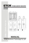
OV-1000 Optical Time
Domain Reflectometer (OTDR)
An Evolant® Solutions Product
Applications
• Testing and troubleshooting of LAN, Telco, CATV and
FTTx networks
Description
Corning Cable Systems OV-1000 Optical Time Domain
Reflectometer (OTDR) provides testing flexibility by combining a rugged platform with field-interchangeable multimode,
single-mode and advanced testing modules. All OTDR modules can be used as continuous wave (CW) light sources.
Available as options on the mainframe are a power meter and
Visual Fault Locator (VFL). The OV-1000 utilizes Windows®
CE technology allowing for a fast power-up time of four
seconds from sleep mode. The OV-1000 has an 80 MB internal flash memory that typically stores up to 1500 traces and
eliminates the need for a hard drive, which can fail under
extreme field conditions. If extra storage capacity is needed,
the unit offers USB A/B ports and a compact flash slot.
OV-1000 OTDR | Photo LAN731
The OV-1000 OTDR product line offers a wide variety of
multimode and single-mode modules. The OV-1000 has the
capacity to hold up to two OTDR modules or one OTDR
module and one advanced testing module at the same time.
Modules can be easily switched out in the field, in just a matter
of seconds, without the use of tools.
The OV-1000 has a 6.4-in color touch screen that is resistant
to shock, water and most common chemicals used in the field.
The screen is large enough to view both the trace and the
event table simultaneously, eliminating the need to toggle
back and forth between the two.
Along with offering three OTDR test modes — Auto,
Advanced and Template Trace — the OV-1000 is future-ready
with the ability to accept protocol testing modules, such as
Gigabit Ethernet, as they are made available.
®
Evolant
Solutions
Product Specifications
EVO-697-EN | Page 1
OV-1000 Optical Time
Domain Reflectometer (OTDR)
An Evolant® Solutions Product
Features / Benefits
• Rugged, splash-proof mainframe allows for testing in harsh
conditions
• 6.4-in color thin-film transistor (TFT) liquid crystal display
(LCD) is easily readable when testing indoors under artificial
light and outdoors in the sunlight
• Dial and keypad make scrolling and selecting faster and easier
• Accommodates up to two field-interchangeable modules,
eliminating the need to change modules as often
• Windows® CE-based technology with four second
power-up time from sleep mode allows the user to begin
testing immediately
• Instantaneous AutoSync USB makes it easier and faster to
transfer files and perform software upgrades
OV-1000 OTDR Kit | Photo LAN730
• Portable file transfer can be achieved via compact flash or
with a USB memory stick
• Touch screen keyboard eliminates the need for an external
keyboard
®
Evolant
Solutions
EVO-697-EN | Page 2
OV-1000 Optical Time
Domain Reflectometer (OTDR)
An Evolant® Solutions Product
Specifications
OV-1000 OTDR Mainframe 1
Parameter
Specification
Display
Color touch screen, 640 x 480 TFT 163 mm (6.4 in)
Interfaces
USB A main; USB B remote; compact flash; fiber inspection probe connector port (video)
Storage
Internal 80 MB (flash); USB stick 2 GB (optional); compact flash cards (optional)
Batteries
Rechargeable lithium ion
2
Battery Operating Time
8 h as per Bellcore TR-NWT-001138
Power Supply
AC/DC adapter, input: 100 to 240 V, 50 to 60 Hz, 2 A max, output; 24 V DC, 90 watts
Operating Temperature
-5º to 50ºC (23º to 122ºF)
Storage Temperature 3
-40º to 70ºC (-40º to 158ºF)
Relative Humidity
0% to 95% max, non-condensing
Size (H x W x D)
32.2 x 19.7 x 10.9 cm (12.6875 x 7.75 x 4.3125 in)
Weight
2.5 kg (5.4 lb)
Vibration
< 1.5 g at 10 to 500 Hz (on 3 main axes)
Mechanical Shock
< 760 mm on 6 sides and 8 main edges (according to GR-196-CORE)
Power Meter 4- Optional
Calibrated Wavelengths (nm)
850, 1300, 1310, 1490, 1550, 1625, 1650
Detector
InGaAs
Power Range (dBm)
10 to -86
Uncertainty
± 5% ± 3 pW (InGaAs)
5
Display Resolution (dB)
0.01 = max to -76 dBm; 0.1 = -76 dBm to -86 dBm; 1 = -86 dBm to min
Automatic Offset
Nulling Range6
Max to -63 dBm for InGaAs
Tone Detection (Hz)
270/1000/2000
Safety
21 CFR 1040.10 and IEC 60825-1:1993 + A2:2001
Visual Fault Locator (VFL)- Optional
Central Wavelength
Laser, 650 nm ± 10 nm
Pulse
Continuous wave (CW)
Typical Power Output7
3 dBm (2 mW)
Notes:
1
All specifications valid at 23°C (73°F).
2
Standard recharge time is 3 hours. Recharge temperature: 0° to 35°C (32° to 95°F).
3
Not including internal batteries. Battery maximum storage temperature: 60°C (140°F).
4
At 23°C ± 1°C, 1550 nm and FC connector. With modules in idle mode. Battery operated.
5
Up to 5 dBm.
6
For ± 0.05 dB, from 18° to 28°C.
7
For 62.5/125 µm fiber.
(continued)
®
Evolant
Solutions
EVO-697-EN | Page 3
OV-1000 Optical Time
Domain Reflectometer (OTDR)
An Evolant® Solutions Product
Specifications (continued)
Multimode Module 1
Model
Wavelength (nm)
Dynamic
Range 2, 3 (dB) Zone 4 (m)
Event Dead
Zone4 (m)
Attenuation
Dead Zone4 (m)
400-MD26 (-V)
850 ± 20/1300 ± 20
27/26
1/1
3/4
Single-mode Modules1
Model
Wavelength (nm)
Dynamic Range 5
at 10 µs (dB)
Dynamic Range 5
at 20 µs (dB)
Event Dead
Zone 6 (m)
Attenuation
Dead Zone 6 (m)
400-SD34 (-V)
1310 ± 20/1550 ± 20
35/34
37/35
1/1
4.5/5
400-SD37 (-V)
1310 ± 20/1550 ± 20
38/37
39/38
1/1
5/6 (4/4)
Model
Wavelength (nm)
Dynamic Range 2, 3, 5
at 10 µs (dB)
Event Dead
Zone 4, 6 (m)
Attenuation
Dead Zone 4, 6(m)
400-MDSD (-V)
850 ± 20/1300 ± 20
1310 ± 20/1550 ± 20
27/26
35/34
1/1
1/1
3/4
4.5/5
Quad Module1
General Specifications
400-MD26/400-MDSD
400-SD34/400-SD37/400-MDSD
Distance Range (km)
0.1, 0.3, 0.5, 1.3, 2.5, 5, 10, 20, 40
1.25, 2.5, 5, 10, 20, 40, 80, 160, 260
Pulse Width (ns)
5, 10, 30, 100, 275, 1000
5, 10, 30, 100, 275, 1000, 10,000, 20,000
Multimode Launch Conditions7
Class CPR 1 or 2
N/A
Linearity (dB/dB)
± 0.03
± 0.03
Loss Threshold (dB)
0.01
0.01
Loss Resolution (dB)
0.001
0.001
Sampling Resolution (m)
0.04 to 2.5
0.04 to 5
Sampling Points
Up to 128,000
Up to 128,000
Distance Uncertainty 8 (m)
± (0.75 + 0.0025% x distance)
± (0.75 + 0.0025% x distance)
Measurement Time
User-defined (60 min. maximum)
Guaranteed: ≤ 0.4
User-defined (60 min. maximum)
Real-time Refresh (s)
Stable Source Output Power 9 (dBm)
-1.5
-8 (SD34, MDSD), -4.5 (SD37)
Recommended Calibration
Cycle (yr)
1
1
Visual Fault Locator10
(optional)
650 nm ± 10 nm, Pout = 3 dBm
650 nm ± 10 nm, Pout = 3 dBm
Guaranteed: ≤ 0.4, Typical: ≤ 0.3
Notes:
1
All specifications valid at 23ºC ± 2ºC (73.4ºF ± 3.6ºF) with an FC/PC connector, unless otherwise specified.
2
Typical dynamic range with longest pulse and three-minute averaging at SNR = 1.
3
Multimode dynamic range is specified for 62.5 µm fiber; a 3 dB reduction is seen when testing 50 µm fiber.
4
Typical dead zone of multimode reflectance below -35 dB and single-mode reflectance below -45 dB, using a 5 ns pulse.
5
Typical dynamic range with three-minute averaging at SNR = 1.
6
Typical dead zone of single-mode modules for reflectance below -45 dB, using a 10 ns pulse (5 ns pulse for 400-SD34/SD37/SD135/ST37/ST137).
7
Controlled launch conditions allow 50 µm and 62.5 µm multimode fiber testing.
8
Does not include uncertainty due to fiber index and sampling resolution.
9
Typical output power is given at 1300 nm for multimode and 1550 nm for single-mode.
10
Power output is for 62.5/125 µm fiber.
®
Evolant
Solutions
EVO-697-EN | Page 4
OV-1000 Optical Time
Domain Reflectometer (OTDR)
An Evolant® Solutions Product
Ordering Information
Part Number
Description
Basic Kits
Basic Kits include OV-1000 Mainframe, power supply, battery, appropriate OTDR adapter(s), CD with OTSView PC emulation
software and user’s manual, cleaning supplies and hard-shell transit case.
1000BK-SD34
Short-Range Dual Single-Mode OTDR (module 400-SD34) with SC and FC OTDR port adapters
1000BK-SD37
Mid-Range Dual Single-Mode OTDR (module 400-SD37) with SC and FC OTDR port adapters
1000BK-MD26
Dual Multimode OTDR (module 400-MD26) with SC and ST ® Compatible OTDR port adapters
1000BK-MDSD
Dual Multimode and Single-Mode OTDR (module 400-MDSD) with SC and
ST Compatible OTDR port adapters
Deluxe Kits
Deluxe Kits include OV-1000 Mainframe with power meter and VFL, power supply, battery, appropriate OTDR port adapters,
CD with OTSView PC emulation software and user’s manual, OTS Batch PC batch processing software, cleaning supplies and
hard-shell transit case.
1000DK-SD34
Short-Range Dual Single-Mode OTDR (module 400-SD34) Mainframe has power meter and VFL,
SC and FC OTDR and meter port adapters, OTS Batch Software
1000DK-SD37
Mid-Range Dual Single-Mode OTDR (module 400-SD37) Mainframe has power meter and VFL,
SC and FC OTDR and meter port adapters, OTS Batch Software
1000DK-MD26
Dual Multimode OTDR (module 400-MD26) Mainframe has power meter and VFL,
SC and ST Compatible OTDR and meter port adapters, OTS Batch Software
1000DK-MDSD
Dual Multimode and Dual Single-Mode OTDR (module 400-MDSD) Mainframe has power meter
and VFL, SC and ST Compatible OTDR and meter port adapters, OTS Batch Software
Mainframes
Standard components on mainframes include 6.4-in color touch screen, USB A/B ports, RJ-45 port and compact flash slot.
1000-MAINF
OTDR Controller (same frame as basic frame)
1000-MAINF-VPM
OTDR Controller with power meter and VFL (same frame as deluxe frame)
OV-1000 Modules
Includes SC OTDR port adapter(s).
400-MD26
Multimode OTDR Module, 850/1300 nm (27/26 dB)
400-SD34
Single-Mode Short-Range OTDR Module, 1310/1550 nm (34/32.5 dB)
400-SD37
Single-Mode Mid-Range OTDR Module, 1310/1550 nm (37/35.5 dB)
400-MDSD
Multimode/Single-Mode Quad OTDR Module, 850/1300/1310/1550 nm (26/25/35/34 dB)
®
Evolant
Solutions
EVO-697-EN | Page 5
OV-1000 Optical Time
Domain Reflectometer (OTDR)
An Evolant® Solutions Product
Ordering Information (continued)
Accessories
UI-SC
Universal Interface Source/OTDR Connector Adapter, SC
UI-ST
Universal Interface Source/OTDR Connector Adapter, ST® Compatible
UI-FC
Universal Interface Source/OTDR Connector Adapter, FC
OA-SC
Power Meter Connector Adapter, SC
OA-ST
Power Meter Connector Adapter, ST Compatible
OA-FC
Power Meter Connector Adapter, FC
OA-LC
Power Meter Connector Adapter, LC
OA-MTRJ
Power Meter Connector Adapter, MTRJ
OTSBATCH
PC Batch Processing Software
CASE-OV-1000
Hard-Shell Transit Case with wheels
PS-OV-1000
Power Supply for 100-240 V AC with US line cord
1000-OV-BATT
Replacement Battery for OV-1000
1000-MEMORY-2G
OV-1000 Memory Stick for 2 GB of USB Storage (Windows® CE compatible)
1000-STYLUS
Replacement Stylus for OV-1000
TE-WARRANTY-1
1-year Extended Warranty, includes all repairs and replacement charges of defective parts
excluding freight; does not include normal, yearly calibration
TE-WARRANTY-2
2-year Extended Warranty, includes all repairs and replacement charges of defective parts
excluding freight; does not include normal, yearly calibration
Accessories- OTDR Access Jumpers
PTF-100M-6P5050
Portable Test Fiber Box, MM 62.5 µm (standard) fiber, ST to ST Connectors, 100 m
PTF-100M-6P3950
Portable Test Fiber Box, MM 62.5 µm (standard) fiber, SC to ST Connectors, 100 m
PTF-100M-6P3939
Portable Test Fiber Box, MM 62.5 µm (standard) fiber, SC to SC Connectors, 100 m
PTF-100M-5P5050
Portable Test Fiber Box, Pretium 300™ Solutions Multimode Laser-optimized,
ST to ST Connectors, 100 m
PTF-100M-5P3950
Portable Test Fiber Box, Pretium 300 Solutions Multimode Laser-optimized,
SC to ST Connectors, 100 m
PTF-300M-SP5865
Portable Test Fiber Box, single-mode fiber, SC UPC to SC APC connectors, 300 m
PTF-300M-SP5454
Portable Test Fiber Box, single-mode fiber, FC UPC to FC UPC connectors, 300 m
PTF-300M-SP5858
Portable Test Fiber Box, single-mode fiber, SC UPC to SC UPC connectors, 300 m
PTF-300M-SP6161
Portable Test Fiber Box, single-mode fiber, ST UPC to ST UPC connectors, 300 m
Note: ST= ST® Compatible Connector
Note: Additional portable test fiber box configurations are available on request. Please contact a Corning Cable Systems Customer Service representative for
more information.
®
Evolant
Solutions
EVO-697-EN | Page 6
OV-1000 Optical Time Domain Reflectometer (OTDR)
Optional Video Probe for Connector Inspection
An Evolant® Solutions Product
Applications
The video probe allows for the inspection of a fiber optic connector’s end-face quality. The resulting images can be used as
documentation of end-face quality and cleanliness.
Description
The hand-held analog video probe is the ideal solution for
inspecting the quality of a fiber optic connector end-face. The
probe’s design and thumb wheel placement allow for an easy
one-hand operation. The magnification control thumb wheel
can be used to adjust the image from 200x to 400x. Likewise,
the focus control wheel is used to bring the image into focus.
Video Probe in Patch Panel | Photo TEQ36
The probe has the National Television System Committee
(NTSC) video output format in order to maintain high-level
analog video quality. A 4-pin output connection allows for a
seamless connection to OV-1000 platform with the supplied
video cable. These images can be saved in JPEG format to the
OV-1000 flash memory.
A variety of precision inspection tips are available for the video
probe. The “universal” tips are used when viewing a patch cord
connector end-face or when viewing a connector before plugging it into the patch panel. The “bulkhead” tips are used when
viewing a connector on the backside of patch panels through
the front of the adapter. This allows for convenient inspection
without removing the connector from the patch panel.
Features / Benefits
• Interfaces with the OV-1000 without the need for an
additional external monitor
Video Probe Connected to OV-1000 | Photo TEQ35
• Interchangeable inspection tips for a variety of connector
types
• 200x to 400x microscope probe in one unit
• Ability to save images for documentation of connector
end-face quality
• Coaxial illumination provides clear view of end-face condition
Contaminated Connector End-Face | Photo NS134
®
Evolant
Solutions
EVO-697-EN | Page 7
OV-1000 Optical Time Domain Reflectometer (OTDR)
Optional Video Probe for Connector Inspection
An Evolant® Solutions Product
Specifications
Model Number
VIP-HH-2-4
End-Face Lighting
Coaxial illumination
Magnification
200x to 400x
Connector Output
4-pin
Video Image Format
NTSC
Still Image Format
JPEG
Ordering Information
Part Number
Description
VIP-HH-2-4
Video Inspection Probe for use with OV-1000; 200x/400x magnification with coaxial lighting;
includes (1) universal 2.5 mm patch cord; transfer cable for OV-1000
VIP-HH-TIP
Video Inspection Probe (VIP-HH-2-4) bulkhead tip set; includes SC, ST and FC tips for viewing
connectors on the backside of the patch panel through the adapter
VIP-HH-TIP-LC
Video Inspection Probe (VIP-HH-2-4) tip set for LC connector; includes (1) LC bulkhead tip for
viewing connectors on the backside of the patch panel through the adapter and (1) 1.25 mm universal
patch cord tip
VIP-HH-TIP-APC
Video Inspection Probe (VIP-HH-2-4) tip set for APC connectors; includes (1) SC APC,
(1) LC APC and (1) FC APC bulkhead tip for viewing connectors on the backside of the patch panel;
(1) 1.25 mm APC and (1) 2.5 mm APC universal adapter for viewing an APC patch cord connectors
VIP-HH-TIPSET-SF
Complete tip set including all tips in VIP-HH-TIP, VIP-HH-TIP-LC and VIP-HH-TIP-APC
VIP-HH-OPTITIP
Video Inspection Probe Tip for viewing the connector end-face on an OptiTip™ MT Plug and Jack;
includes a scroll knob to pan across the connector end-face
VIP-HH-OPTITAP
Video Inspection Probe tip set for viewing the connector end-face on an OptiTap™ Connector and
an OptiTap™ Connector port
Note: Additional inspection tips are available upon request. Please contact a Corning Cable Systems Customer Service Representative for more information.
Note: ST= ST® Compatible Connector
®
Evolant
Solutions
EVO-697-EN | Page 8
OV-1000 Optical Time Domain Reflectometer (OTDR)
Optional Ethernet Module
An Evolant® Solutions Product
Applications
This Gigabit Ethernet testing module brings performance
assurance to Ethernet-based services. Its testing functionality
provides all the necessary measurement tools for verifying connectivity in its native format: 10/100/1000BaseT, 1000BaseSX,
1000BaseLX and 1000BaseZX.
Description
The Gigabit Testing Module offers three essential Ethernet
testing methods:
Ethernet Performance Validation (RFC 2544)
The Internet Engineering Task Force (IETF) has put together
a test methodology to address the issues of performance
verification at the layer two and three levels. RFC 2544, a
“Benchmarking Methodology for Network Interconnect
Devices,” specifies the requirements and procedures for testing
throughput, back-to-back frames (burst), frame loss and latency.
The Gigabit Testing Module can perform the RFC 2544 test
suite for 10/100/1000BaseT and optical GigE interfaces at all
frame sizes and at full-line rate. The Gigabit Testing Module
supports automated RFC 2544 testing, which helps ensure
repeatable results. Automation also provides ease of use for
field technicians by enabling accurate, efficient measurements
and results through a clear and simple pass/fail indication.
Gigabit Ethernet Module | Photo TEQ33
Bit-Error Rate Testing (BERT)
Ethernet is increasingly carried across a variety of layer-one
media for longer distances. This creates a growing need for
the certification of Ethernet transport on a bit-per-bit basis,
which can be done using bit-error rate testing (BERT).
BERT uses a pseudo-random binary sequence (PRBS) encapsulated into an Ethernet frame, making it possible to go from a
frame-based error measurement to a bit-error-rate measurement. This provides the bit-per-bit error count accuracy
required for the acceptance testing of physical-medium transport systems. BERT over Ethernet should usually be used
when Ethernet is carried transparently over layer-one media.
®
Evolant
Solutions
Gigabit Ethernet Module in OV-1000 | Photo TEQ34
EVO-697-EN | Page 9
OV-1000 Optical Time Domain Reflectometer (OTDR)
Optional Ethernet Module
An Evolant® Solutions Product
Description (continued)
Quality of Service (Frame Analysis)
Data services are making a significant shift towards supporting
a variety of applications on the same network. This shift has
fuelled the need for quality of service (QoS) testing to ensure
the condition and reliability of services. Service providers need
to assign different qualities of service to each type of service
they offer. By providing the ability to configure different
Ethernet and IP QoS parameters such as VLAN ID (802.1Q),
VLAN priority (802.1p), VLAN stacking (802.1ad Q-in-Q),
ToS and DSCP on multiple streams, the Gigabit Testing
Module allows service providers to simulate and qualify different types of applications running over their Ethernet network.
Diverter with Media Converter | Photo TEQ31
This frame analysis feature enables multi-stream traffic
generation and analysis allowing for the troubleshooting of
Ethernet circuits as well as customer-traffic analysis and error
identification. Thanks to its packet jitter-measurement capability (RFC 3393), the Gigabit Testing Module lets service
providers efficiently benchmark transport networks when it
comes to delay-sensitive traffic such as voice and video over IP.
Features / Benefits
• Module is compatible with OV-1000 mainframe
• Unit can be used in multiple configurations for tesing;
module to module (requires two modules); module to switch
(requires an installed switch and one gigabit module); or
module to diverter (requires one module and the diverter)
• Simultanious traffic generation and reception at
100 percent wire speed for 10/100/1000BaseT,
1000BaseSX, 1000BaseLX or 1000BaseZX
full-duplex networks at all packet sizes
• Can test both copper (10/100/1000BaseT) and optical
(1000BaseSX, LX or ZX) based networks
• Transmits and analyzes multiple streams, perfect
for installing, commissioning and maintaining
Ethernet networks
• Measures throughput, back-to-back, latency and frame loss as
per RFC 2544
• Expert-mode capability to set test thresholds for
clear pass/fail test results
• Performs packet jitter measurement (IP packet-delay variation
as per RFC 3393) to qualify Ethernet transport networks for
transmission of delay-sensitive traffic such as voice over IP
(VoIP) and video
• Easy-to-use smart user interface (SUI) for
configurable screens, customization of test suites,
as well as performance reporting real-time and
historical performance
• EtherBERT for bit-error-rate testing of 10, 100
and 1000 Mb/s Ethernet
®
Evolant
Solutions
EVO-697-EN | Page 10
OV-1000 Optical Time Domain Reflectometer (OTDR)
Optional Ethernet Module
An Evolant® Solutions Product
Specifications
Optical Interfaces
1000-SFP-850
1000-SFP-1310
1000-SFP-1550
PMD
1000BaseSX
1000BaseLX
1000BaseZX
Wavelength (nm)
850
1310
1550
Tx Level (dBm)
-9 to -3
-9.5 to -3
0 to +5
Rx Level Sensitivity (dBm)
-20
-22
-22
Maximum reach
550 m
10 km
80 km
Transmission Bit Rate (Gb/s)
1.25
1.25
1.25
Reception Bit Rate (Gb/s)
1.25
Tx Operational Wavelength Range (nm) 830 to 860
1.25
1.25
1270 to 1360
1540 to 1570
DFB
Laser type
VCSEL
FP
Eye safety
CLASS 1
CLASS 1
CLASS 1
Connector
LC
LC
LC
Transceiver type
SFP
SFP
SFP
Electrical Interfaces
10BaseT
100BaseT
1000BaseT
Tx bit rate
10 Mb/s
125 Mb/s
1 Gb/s
Tx accuracy (ppm)
±100
±100
±100
Rx bit rate
10 Mb/s
125 Mb/s
1 Gb/s
Rx measurement accuracy (ppm)
±4.6
±4.6
±4.6
Duplex mode
Half and full duplex
Half and full duplex
Full duplex only
Jitter compliance
IEEE 802.3
ANSI X3.263-1995
IEEE 802.3
Connector
RJ-45
RJ-45
RJ-45
Maximum reach (m)
100
100
100
Gigabit Module
1000-GIG-MOD
Ports
(1) 10/100BaseT (1) 10/100/1000BaseT and (1) SFP port for GigE
Connector types
RJ-45 (ISO 8877) and SFP
Connector speed (Mb/s)
10/100/1000
Duplex mode
Full/half duplex Auto-negotiation
Maximum port capacity (Mb/s)
2000 (bi-directional)
Size (H x W x D)
250 mm x 96 mm x 260
Weight (without transceivers)
0.5 kg (1.1 lb)
Operating Temperature
32°F to 104°F (0°C to 40°C)
®
Evolant
Solutions
EVO-697-EN | Page 11
OV-1000 Optical Time Domain Reflectometer (OTDR)
Optional Ethernet Module
An Evolant® Solutions Product
Ordering Information
Part Number
Description
1000-GIG-MOD
Gigabit Ethernet Testing Module for OV-1000 platform; module has two 10/100/1000BaseT and
1 Gigabit Ethernet SFP optical port; performs RFC 2544, BERT and frame analysis
1000-SFP-850
1000BaseSX (850 nm) Optical SFP Transceiver Module with LC connectors for gigabit testing
module (VCSEL source)
1000-SFP-1310
1000BaseLX (1310 nm) Optical SFP Transceiver Module with LC connectors for gigabit testing
module (FP Laser source)
1000-SFP-1550
1000BaseZX (850 nm) Optical SFP Transceiver Module with LC connectors for gigabit testing
module (DFB Laser source)
1000-DIVERTER
Diverter for Gigabit Ethernet testing; includes Ethernet Network Interface Unit with a
loop back testing feature with RJ45 interface; also includes a media converter with SFP interface;
power supplies and manual; SFP purchased separately
Corning Cable Systems LLC • PO Box 489 • Hickory, NC 28603-0489 USA
800-743-2675 • FAX: 828-901-5973 • International: +1-828-901-5000 • www.corning.com/cablesystems
®
Evolant
Solutions
Corning Cable Systems reserves the right to improve, enhance and modify the features and specifications of Corning Cable Systems products
without prior notification. Evolant is a registered trademark of Corning Cable Systems Brands, Inc. OptiTap, OptiTip, OptiVisor and Pretium are
trademarks of Corning Cable Systems Brands, Inc. ST is a registered trademark of Lucent Technologies. All other trademarks are the properties of
their respective owners. Corning Cable Systems is ISO 9001 certified. © 2007 Corning Cable Systems. All rights reserved. Published in the USA.
EVO-697-EN / April 2007
EVO-697-EN | Page 12