1
VersaMax
Discrete Output Modules
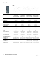
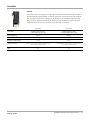
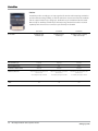
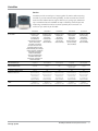
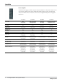
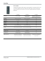
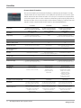
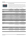
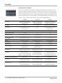
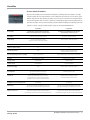
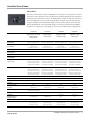
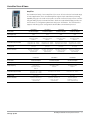
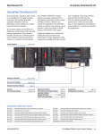
Discrete output modules send control signals to devices such as contactors, indicator lamps, and
interposing relays that can also have two states. Modules require a carrier base (IC200CHSxxx).
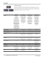
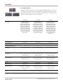
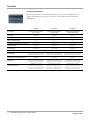
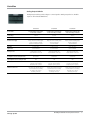
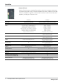
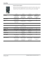
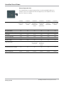
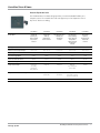
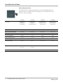
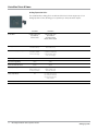
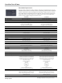
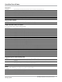
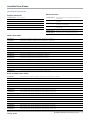
IC200MDL742
IC200MDL743
IC200MDL744
Product Name
VersaMax Discrete Output Module,
24 VDC Positive Logic 0.5A with
ESCP, 32 points
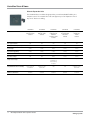
VersaMax Discrete Output Module,
5/12/24 VDC Negative Logic, 0.5 A per
point (1 group of 16) 16 points
VersaMax Discrete Output Module,
5/12/24 VDC Negative Logic, 0.5 A per
point (2 groups of 16) 32 points
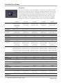
Output Voltage
18-30 VDC, 24 VDC nominal
5/12/24 VDC
5/12/24 VDC
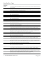
Number of Points
32
16 (1 group of 16)
32 (2 groups of 16)
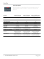
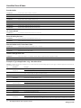
Channel to Channel Isolation
No
No
No
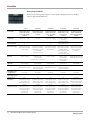
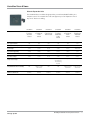
0.5 A per point
0.5 A per point
0.5 A per point
0.5/0.5
0.2/1.0
0.2/1.0
Short circuit protection, overcurrent
protection, free-wheeling
diodes (each output)
No internal fuse
No internal fuse
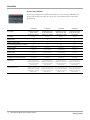
2 groups of 16
1 group of 16
2 groups of 16
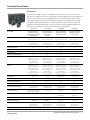
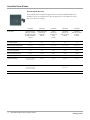
18-30 VDC, 24 VDC nominal
4.75 to 5.25 VDC, 5 VDC nominal
for 5 VDC-TTL mode; 10.2 to 30 VDC,
12/24 VDC nominal for 12/24 VDC mode
4.75 to 5.25 VDC, 5 VDC nominal
for 5 VDC-TTL mode; 10.2 to 30 VDC,
12/24 VDC nominal for 12/24 VDC mode
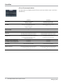
0.5 A at 30 VDC maximum (resistive);
2.0 A inrush maximum for 100 ms
25 mA maximum for 5 VDC-TTL mode,
0.5 A at 30 VDC maximum,
2.0 A inrush maximum for 100 ms
for 12/24 VDC mode
25 mA maximum for 5 VDC-TTL mode,
0.5 A at 30 VDC maximum,
2.0 A inrush maximum for 100 ms
for 12/24 VDC mode
150 maximum
70 maximum
140 maximum
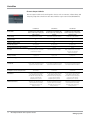
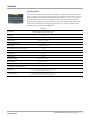
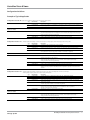
LED Indicators
One LED per point shows individual
point ON/OFF state (logic side).
FLD PWR LED indicates field power is
present. OK LED indicates backplane
power is present.
One LED per point shows individual
point ON/OFF state (logic side).
FLD PWR LED indicates field power is
present. OK LED indicates backplane
power is present.
One LED per point shows individual
point ON/OFF state (logic side).
FLD PWR LED indicates field power is
present. OK LED indicates backplane
power is present.
Dimensions (W x H x D)
110 mm (4.3 in) x 66.8 mm (2.63 in)
x 50 mm (1.956 in), not including the
height of the carrier or the
mating connectors
110 mm (4.3 in) x 66.8 mm (2.63 in)
x 50 mm (1.956 in), not including the
height of the carrier or the
mating connectors
110 mm (4.3 in) x 66.8 mm (2.63 in)
x 50 mm (1.956 in), not including the
height of the carrier or the
mating connectors
Load Current per Point
Input and Output Response Time- On/Off (ms)
Protection
Points per Common
External Power Supply
Load Current
5V Backplane Current Consumption (mA)
www.ge-ip.com
GE Intelligent Platforms Control Systems Solutions
193