1
Chapter 2. Thermal Vacuum Chamber
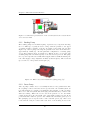
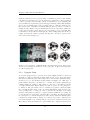
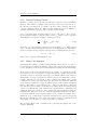
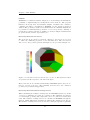
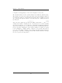
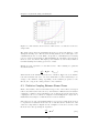
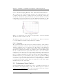
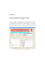
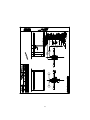
Figure 2.13: The systems overview screen in the human machine interface.
The vacuum system status can be seen in the system mimic box. The control
surface temperatures are illustrated through the three octagons. The presented
temperatures are equivalent to the values serving as cooling control input. The
check-boxes located next to the octagons allow the user to decide which control surfaces that are to be controlled actively during a hot thermal cycle. The
operating state of the cryogenic valves as well as the liquid nitrogen status is
visualized to the right in the figure. Several buttons are placed in the top left
corner of Figure 2.13. These buttons enable the user to: initiate pump-down/up
sequence, edit the thermal cycle to be executed, execute the specified cycle, etc.
2.3.2 Manual Control
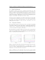
It is possible to execute manual cooling cycle control through the HMI. Manual
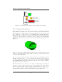
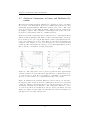
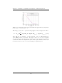
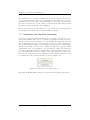
control is enabled in the configuration dialog box, partly illustrated in Figure 2.14, by clicking the push button labeled Service mode. A dialog box appears where the Non interrupted mode should be selected. Once situated in this
mode of operation, the user can control the state of each pneumatically controlled valve through the check boxes seen in the figure. Since the heat control is
20