1
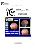
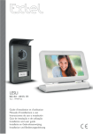
520060 (1)
CONTENTS
1 PRESENTATION
OF THE TOOL
DIAG NG3
1.1 Advantages ................................................................ 04
• Congratulations ............................................................................. 04
• Performance and user friendliness ................................................... 04
1.2 Description .................................................................. 05
• Tablet ........................................................................................... 05
• VCI ............................................................................................... 09
• Cables........................................................................................... 10
1.3 Options ....................................................................... 11
• Workshop terminal ........................................................................ 11
• Endoscope .................................................................................... 12
1.4 Before usage .............................................................. 13
• Access to documentation ................................................................ 13
• Warning ....................................................................................... 13
2 START
UP
2.1 Connections ................................................................ 14
• Connection diagram ...................................................................... 14
• Mode of communication between the VCI and the tablet ................. 14
• Precautions .................................................................................... 15
1
2.2 CD to insert ................................................................. 16
• Usage instructions ......................................................................... 16
• Start button ................................................................................... 17
• Power supply LED .......................................................................... 17
2.3 Choice of language ..................................................... 18
2.4 Main menu navigator .................................................. 19
2.5 Taskbar navigator ...................................................... 21
2.6 VCI / Tablet pairing ..................................................... 22
• Warning........................................................................................ 22
• Procedure ...................................................................................... 22
3. MAINTENANCE
3.1 Important ................................................................... 23
• Environment .................................................................................. 23
3.2 Wiring ........................................................................ 24
• Connectors of the tablet ................................................................. 24
• Connectors of the VCI .................................................................... 26
3.3 Battery ....................................................................... 27
• Safety instructions .......................................................................... 27
• Indicator lamps ............................................................................. 28
• Management of battery charging and discharging .......................... 28
• Replacement of internal battery ...................................................... 29
3.4 Management of cards ................................................. 30
• Insertion of the radio-frequency PCMCIA card ................................ 30
• Insertion of the smart card ............................................................. 30
2
3.5 In case of malfunctioning ............................................ 31
• case 1 : The tablet does not start .................................................... 31
• case 2 : No communication between the tablet and the VCI .............. 32
• case 3 : No communication with the vehicle..................................... 33
• case 4 : VCI power supply indicator is not lit ................................... 34
4. AFTER-SALES
SERVICE
4.1 Services proposed ....................................................... 35
• Hot-Line Actia Muller Services telephone and technical support ......... 35
• Standard replacement ................................................................... 36
• Breakage ...................................................................................... 37
• State of tools ................................................................................. 38
• Accessories ................................................................................... 38
4.2 After-sales service ....................................................... 39
3
Presentation of diagnostic tool
Diag NG3
1.1 ADVANTAGES
Congratulations!
Thank you for purchasing the RENAULT TRUCKS diagnostic tool Diag NG3.
The design of this tool, resulting from a close co-operation between RENAULT TRUCKS and ACTIA,
is based on a marketing survey conducted by RENAULT TRUCKS in its after-sales network. Both
RENAULT TRUCKS and ACTIA, believe that you deserve a high-tech tool that is powerful, longlasting, easy to use and perfectly suited to your needs.
Performance and user friendliness
Your diagnostics will be more advanced, more effective and more accurate, by using the tool Diag NG3.
It adapts itself to developments in vehicle design.
The accessories were specially designed for Diag NG3 in order to help you resolve the most complex
problems simply and easily:
• Host station,
• Trolley,
• Cables,
• Additional batteries,
• Endoscope.
Using the wireless radio-frequency technology equipping the Diag NG3, you can now move about
without any constraint in the workshop, receive dependable W-Data and connect to the Dealernet
without worrying about the cables and connections.
4
1.2 GENERAL
DESCRIPTION OF THE PRODUCT
TABLET
Stylus
5
CD-ROM
Drive
Location of the
smart card
6
Ethernet
Microphone
Battery housing
Folding feet
Fold-out foot
Location of card
for radio link
Location of ACTIA
identification label
7
Power
supply unit
8
VCI
Activity
Error
Power supply
Location of ACTIA
identification label
Vehicle
9
Tablet
CABLES
911639
Diagnostic cable Electricfil
10
911640
Diagnostic cable OBD
911641
911670
Portable/VCI cable
Infomax cable
1.3 OPTIONS
WORKSHOP TERMINAL
The workshop terminal is a radio frequency computer system allowing the tablet
to access the services proposed by the Dealernet, without a wire connection to
the computer network of the site. A workshop terminal can be used
simultaneously by several Diag NG3 tablet (maximum 15).
Preliminary
For using the workshop terminal, a preliminary physical installation (connection to the power supply
and the computer network), as well as a software configuration are required.
Proceed as follows for configuring your workshop terminal:
1 Select the item Configuration from the main menu, then the item Workshop terminal.
Then, follow the instructions displayed on the screen.
2 After configuring the workshop terminal, we recommend that you print out the information
relating to this configuration.
In case your equipment is replaced during servicing, it shall be necessary to create a new
configuration.
WARNING
The use of several workshop terminals at the same site requires special precautions. Contact
the after-sale service point nearest to you before purchasing a new workshop terminal (the
list of Actia Muller Services service points can be found on the last page of this document).
11
ENDOSCOPE
Description and principal technical characters
The principal function of the ACTIA endoscope is to view the parts of a vehicle inaccessible to the naked
eye, for checking them.
This system is composed of several elements:
A central flexible tube with a shape memory, to which are connected:
• An optical unit allowing an axial view and a 90° view.
• An optical unit allowing a 120° view (in option).
• A module for a cable connection to Diag NG3.
• A radio module allowing a wireless communication
with the Diag NG3 tablet, for a total freedom of
movement (in option).
• A software application in the form of CD for saving
and displaying the images.
The power supply is provided via the Diag NG3 connection and in
the radio frequency mode, by a rechargeable battery incorporated in the handle.
Scope and functions of ACTIA endoscope
Passing through the injector or the spark plug holes, the ACTIA endoscope allows viewing in real time:
• The cylinders (checking the surface conditions of the sleeves and the valves)
• The engine compartment (detection of leaks and checking the condition of connections)
• The interior of manifolds...
The ACTIA endoscope allows saving the photos.
12
1.4 BEFORE
USAGE
Continuous access to the documentation
For a double archiving source (paper, Diag NG3), we suggest that you keep the user documentation
always near you, either by printing it out or by installing it on your PC.
For printing the onboard documentation, connect a printer to the Diag NG3.
For an electronic access to the documentation contained on the start-up CD, import it on your personal
PC.
You have to install the Acrobat Reader (free software for reading .pdf files) on your PC
for reading this documentation.
13
WARNING
• Before using the equipment, read the chapter on the battery.
• Use the Diag NG3 according to the instructions provided by ACTIA.
• Place only the stylus in contact with the tactile pad.
• Always use preferably the exit icon located on the main menu for
shutting down the Diag NG3 tool.
• This equipment is designed exclusively for a professional use.
• Power supply voltage from 8 V to 32 V.
Start up
2.1 CONNECTIONS
Connection diagram
Your Diag NG3 tool is composed of two sub-assemblies:
• Diag NG3 Tablet,
• Radio Frequency VCI.
Connect these components according to the following diagram:
+
+
Cable 911641
VCI to tablet communication mode
These two sub-assemblies can communicate with each other via:
Radio frequency link OR Wired link.
The radio frequency link is used in the nominal operating mode.
14
Precautions during the radio frequency link mode:
•For implementing the radio frequency link between the tablet and the VCI, you must first pair the
two sub-assemblies (refer Section 2.4 Pairing)
•Your diagnostic tool is equipped with a wi-fi radio frequency link type 802.11B. The legislation
in force relating to the use of radio frequency bandwidths satisfies the local regulations. Before
using it outdoors, make sure that it is authorised by the local regulations.
•The radio frequency link has a range of about 20 m. An indicator
informs you continuously of the quality of the link. When the quality
indication shows less than 50, bring the tablet closer to the VCI.
•In case the radio signal is lost and if the cable between the tablet and the
VCI is connected, the two sub-assemblies can communicate via the wired link. However, if the
loss of radio signal occurs during a diagnostic session, the automatic passage to wired mode
shall take place after the detection of a transmission error.
15
2.2 CD
TO INSERT
(PLACING
IN
DVD
Usage instructions
The CD box contains two CDs:
• Recovery CD: Usable only on the Diag NG3 tool
(troubleshooting CD)
• Start-up CD: Usable on any PC
(for retrieving the user manual)
16
BOX)
Start button:
You can execute different actions depending on the period
you keep the start button pressed.
For each action executed, the start button emits a different
sound signal:
Button pressing period Sound signal
Action executed
Usage instructions
About 1 second
1 short bip
Starting the tool
About 2 seconds
2 short bips
Shutting down the tool.
To be used only
when the function
shut down tool,
available from the main menu,
does not function.
About 3 seconds
3 short bips
Restart and reinitialise the tool
To be avoided.
About 4 seconds
1 long bip
Cancel any erroneous
manipulation of the button.
In normal use, only the starting short bip should be used.
Power supply LED
The indicator on the left of the front panel indicates the operating status of the tablet:
• Turned off : Tool shut down
• Green: Tool in operation, power supply from an external source (vehicle, power supply unit
or terminal of the host station)
• Orange: Tool in operation, supplied from its internal battery.
17
2.3 CHOICE
18
OF LANGUAGE
2.4 MAIN
MENU NAVIGATOR
The main menu presents you the principal functions of your tool.
Place the stylus on the icon on the function you wish to activate.
Tablet serial
number
19
VCI serial
number
Sofware
version
RF link quality
indicator
Tablet
autonomy
Displays the serial number of the tablet (see tablet presentation label)
Displays the serial number of the paired VCI, displays ???? if no pairing is made
(see VCI presentation label)
Displays the version number of the RENAULT TRUCKS software update (CD V0.0 initial)
Displays the radio frequency signal quality between the VCI and the tablet or between the tablet and the
workshop terminal.
Displays the remaining autonomy of the tablet if the power is supplied by the internal battery.
Accessible function
Description
Shut down
Configuration
Services
Diagnostic
Accessories
Shuts down the tablet
for access to the configuration screen (for example, updating, pairing, etc.)
Provides access to some of the services offered (for example, Dealernet)
Provides access to the RENAULT TRUCKS diagnostic software
Provides access to the functions relating to accessories
(for example, workshop terminal, endoscope, measurement unit)
Provides access to the user documentation
User manual
20
2.5 TASKBAR
NAVIGATOR
For displaying the task bar allowing you to access rapidly the software functions (for example, virtual
keyboard, W-DATA, …), press the button Taskbar.
Press the button again for hiding the Taskbar.
21
Taskbar access
button
2.6 VCI /
TABLET PAIRING
The two sub-assemblies can be synchronised exclusively by a pairing.
A tablet can function with ONE and only one VCI.
A VCI can function with ONE and only one tablet.
WARNING : If one of the sub-assemblies is changed, carry out a fresh pairing.
Procedure
1)
2)
3)
4)
Connect the cable between the NG3 tool and the VCI.
Connect the cable between the VCI and diagnostic socket of a vehicle.
Switch on power to the tablet.
Check the lighting of the green indicator on the VCI.
911640
911641
911639
5)
6)
7)
8)
22
Select the item Configuration from the main menu.
Select VCI from the Configuration screen.
Then, select Pairing.
Your tablet and the VCI are paired, the serial number of the paired VCI is
displayed at the bottom of the main menu screen.
Maintenance
3.1 IMPORTANT
Environment
• Use the equipment at an ambient temperature of 0 to 45°C.
• Do not use the equipment during 1 hour following a sudden change of temperature (condensation
problem).
• Protect the equipment from a prolonged exposure to sunlight.
• Do not place the equipment near sources of inflammable liquids for preventing risks of fire and
explosions.
• Do not leave the cables and the peripherals near a source of heat or burning materials.
• Do not use the equipment under rain or on a wet surface for preventing any risk of electrocution
and damages to the equipment.
• Do not splash liquids on the equipment (water, acid, cleaning materials, etc.)
• Do not drop the equipment.
• Never block the ventilation grill placed under the equipment.
• Do not open the equipment.
• Do not attempt using software other than those supplied with the equipment or by RENAULT
TRUCKS.
• Clean the tablet with a damp, soft cloth.
• The CD-ROM ejection trap should be immediately replaced after inserting or removing
a CD-ROM, in order to keep the reading head clean.
• Do not use solvents for cleaning the Diag NG3.
23
Ethernet
3.2 Wiring
Connectors of the tablet
Microphone
Earphones
Location of card
for radio link
24
Power
Bloc
d'alimentation
supply
unit
Serial link (RS232)
1
2
3
4
5
6
7
8
9
10
11
12
13
14
15
16
17-25
25
Carrier detection
Carrier reception
Data transmission
Terminal ready
Ground signal
Data ready
Ask for sending
Ringing signal
External keyboard USB link
Data
Not used
+5Vcc
Clock
+5V
USB
USB +
Ground
Parallel link
(printer)
Strobage
D0
D1
D2
D3
D4
D5
D6
D7
Accuse receipt
Busy
End paper
Selection
Auto line jump
Printer init.
Entry select.
Ground signal
Power suplly link
Ground
NC
+ 15V
External screen
VCI link
Analog output (red)
Analog output (green)
Analog output (green)
RXD
NC
Ground
Analog ground (red)
Analog ground green)
Analog ground (blue)
Key
Analog ground
NC
NC
Horizontal sync.
Vertical sync.
Reserved
TXD
RTS
CTS
DSR
DTR
NC
NC
+BAT
R100
R100
Ground
Connectors of the VCI
BANTAMATE - 19pts
123456789-
26
+ BAT
+ APC
Ground
ISO 0
ISO 1
ISO 2
ISO 3
ISO 4
ISO 5
10111213141516171819-
ISO 6
ISO 7
Ground
SAE 0
SAE 1
Ground
CAN_H
CAN_L
Ground
ID_DIAG
BANTAMATE - 19pts
123456789101112-
RXD
TXD
RTS
CTS
DSR
DTR
RNG
DCD
+ BAT
ID_B12PTS
Ground
Ground
3.3 BATTERY
The Diag NG3 tool is equipped with an intelligent battery having an autonomy of about 1hour 40
minutes.
Safety instructions
• In case the tool is not used, turn it off for preserving the autonomy.
• Do not use the battery for a different application.
• Use only batteries supplied by our after-sales service.
• Do not store your tool for more than 3 months without connecting to the line supply.
• Do not dismantle the battery, except for a standard replacement.
• Do not open the battery.
• Do not charge the battery without the tool.
• Do not short-circuit its terminals.
• Place the battery away from a source of fire.
In order to preserve the life of your battery, we recommend that you should periodically
discharge the battery totally and recharge it fully again.
27
Indicator lamps
The indicator lamp to the right on the front panel indicates the battery condition:
• Flashing green: Charging in progress.
When the tool is turned off, the charging continues. In case of loss of power supply, the
charging shall restart when a source of energy is detected again.
•
•
•
•
Fixed green: Charging completed and / or relative charge = 100%.
Turn off: autonomy comprised from 35 % to 100 %.
Slow flashing red: autonomy comprised from 5 % to 35 %.
Fast flashing red + sound signal: autonomy less than 5 % (extinction of the tool imminent,
you must immediately stop all the work in progress or connect to a source of power).
Management of battery charging and discharging
When the autonomy of your battery is less than 90 % of the nominal capacity and the charging
conditions are satisfied (battery temperature less than 45°C and availability of line power), the battery
charging is operational.
When the power supply source is lost, the charging shall be stopped. It shall continue
again when the power supply becomes available again.
28
Replacement of internal battery
Provides as follows for replacing the internal battery of the tablet:
• Turn off the tablet imperatively.
• Disconnect the power supply sources (line power cable and the VCI/Tablet cable).
• Remove the two screws on the battery cover.
• Remove the battery from its housing.
• Disconnect the battery.
• Carry out the operations in reverse order for remounting the battery.
Use only a battery having the ACTIA reference (Ref: AC424004) obtained from the ACTIA after-sales
service.
29
3.4 MANAGEMENT
OF CARDS
Insertion of the radio frequency PCMCIA card
Your tool is equipped with a PCMCIA card slot in which the
radio frequency PCMCIA card is inserted.
Limit yourself to the following interventions,
because the card is fragile.
• The card must be inserted in the right hand compartment
of the tool with the coloured surface on top.
• For removing the card, use the ejector located to the left
of the card.
Insertion of the smart card
Your tool is equipped with a smart card reader into which you
can insert the RENAULT TRUCKS smart card.
• The card must be inserted in the left hand compartment
(the face with the coloured RENAULT TRUCKS logo to
the top).
• For removing the card, pull it out.
30
3.5 IN
CASE OF MALFUNCTIONING
Case 1 : The tablet does not start.
Connect
correctly
no
Verification connection
to power supply unit
Does the screen start
after 45s ?
yes
The warning light on
when tablet is
switched on?
yes
no
no
The tablet works
31
Connection correct ?
Contact After-Sale
service
yes
yes
no
Beep when power
supply key pressed?
Case 2 : No communication between the VCI and the tablet
See VCI
power supply
Pair the tablet
and the VCI
no
VCI green light on?
yes
Close up tablet
and VCI
no
Check that the VCI
serial at the bottom of
the first page is the
same as the n° at the
back of the VCI
no
Is the level correct ?
yes
Is the level
correct now ?
yes
The tablet works
no
32
Contact After-Sale
service
yes
Are the number
identical ?
Check that the quality
of the radio signal
displayed at the first
page is satisfactory
(level > 50)
Case 3 : No communication with the vehicle
See VCI
power supply
diagram
no
VCI green light on?
yes
When information
asked from to the
vehicle check that the
VCI yellow light turns
on and off
(before the error
message displays)
It appears that the
problem is related to the
vehicle. Check that you
have selected a suitable
calculator and that the
operating procedure you
follow is right
33
no
yes
Has the yellow monitor
turn on?
no
Check that the
communication
between the tablet
and the VCI is correct
(see diagram 2)
Case 4 : VCI power supply indicator is not lit
Connect VCI
to vehicle
no
Vehicle VCI
connection check
yes
Connection correct ?
yes
Power supply unit
present ?
no
Repair the vehicle
34
yes
Contact After-Sale
service
Check presence +
battery on vehicle
connector
After-sales service
4.1 SERVICES
PROPOSED
While purchasing this tool, you undertake to follow the user instructions specified in the user manual.
Hot Line Actia Muller Services telephone and technical support:
The support service is meant for helping you to distinguish an improper use of the equipment from a real
malfunctioning.
Contact the support service for obtaining an initial evaluation of the source of problem and the first
elements allowing you to resolve a problem of malfunctioning of your diagnostic tool not linked to the
use of RENAULT TRUCKS software.
Depending on the problem identified, we shall make a preliminary technical diagnosis.
We shall then validate the warranty coverage of your diagnostic tool.
Type of problem
Contact
Telephone
Diagnostic tool
The Tech Line France RENAULT TRUCKS
+ 33 4 72 96 20 00.
Equipment
The Hot Line Actia Muller Services
+ 33 2 37 33 42 20
Software
The Tech Line France RENAULT TRUCKS
+ 33 4 72 96 20 00
If the tool has to be returned, we request you to:
• Enclose obligatorily the anomaly report during each return
• Return only the damaged equipment
• Do not return any accessories (cable or battery)
• Return the tablet tool of Diag NG3 with its radio card.
35
If you are unable to reach the Hot Line, (overload, outside the working hours, etc.)
an answering machine shall receive your call and provide you with our fax no.,
the working hours.
WORKING HOURS
For all the telephonic support services, the working hours are:
From Monday to Thursday
from 8.30 a.m To 12.00 p.m, and from 2.00 p.m to 5.30 p.m
Friday
from 8.30 a.m to 12.00 p.m, and from 2.00 a.m to 5.00 p.m
Do not hesitate to leave a message on the answering machine, we shall call you back very soon!
Standard replacement
On decision of the Hot Line Actia Muller Services, a standard replacement of your diagnostic tool shall
be made, subject to a normal use of the product.
This service, provided by us, consists in replacing the defective tool by a tool in working condition at your
site.
The standard replacement service does not cover:
• The cases of breakage that are noted by ACTIA on reception of the returned product even
though this is not mentioned by you during your first call to the Hot Line Actia Muller
Services. A repair estimate shall be sent to you.
• Equipment from the previous generation: DIAGNOSTICA I and DIAGNOSTICA II.
• The technical modifications made by you to the products, the responsibility for which
cannot be attributed to ACTIA or to RENAULT TRUCKS.
• Software updates
• Any product opened without the written permission of ACTIA, with its tamperproof seal
broken.
36
It is not necessary to open the product while replacing the consumables (battery, etc.).
• Absence of radio frequency card in the returned main tool: In this case, the card shall be billed to
you.
• The repair of products damaged due to shock, burning, cutting, perforation, modification of external
appearance, modifications of the product’s hardware configuration (hard disk, RAM, etc.) and
problems caused by a hardware environment not specified in the user manual (for example,
breakage of screen) will be invoiced to the customer.
• Due to their nature, the products identified as accessories or consumables (for example, battery,
cables) remain outside the scope of standard replacement service.
• The accessories directly procured by RENAULT TRUCKS from third party suppliers are not
included in this contract (example: endoscope, etc.). The services proposed do not include the
periodical standardisation / calibration of the products.
Breakage
In case of breakage of your diagnostic tool, please contact the Hot Line Actia Muller Services.
If your diagnostic tool is damaged due to negligence or accident, (notably breakage of screen, box,
radio PCMCIA antenna, customisation of product), an estimate shall be provided to you free of cost
after contact with the telephonic technical support service.
After receiving the acceptance of the estimate, we shall initiate the appropriate replacement procedure
as well as the associated billing, so that you are operational again very soon.
37
State of tools
The products reconditioned by the after-sales service shall have the same software state as new products,
that is, a minimum factory software configuration. You need only install the software supplied on CDROM when purchasing the Diag NG3 as well as the latest software updates received from RENAULT
TRUCKS.
The product restored in this manner is ready for use, with a definition similar to that of the product
received by ACTIA.
In case of a standard replacement for a new product (that is, purchased less than one month ago), a new
product shall be supplied to you.
Accessories:
If you wish to order an accessory, please contact the Hot Line Actia Muller Services who shall provide
you the suitable order form.
The Hot Line Actia Muller Services is at your disposition for informing you the latest prices.
Supplier Référence
38
Item
AC963320
Portable tablet tool Diagnostica III
AC963311
“Light” tool (prices subject to change)
AC963300
VCI-RF
AC963310
VCI-LS
AC540004
Power supply unit for standard tablet tool
AC424004
Internal battery for standard tablet tool
AC963900
Set of 3 stylus
AC911639
Diagnostic cable ELECTRICFIL – VCI-RF / VCI-LS
AC911640
Diagnostic cable OBD – VCI-RF / VCI-LS
AC911670
Infomax cable (according to definition as on 02/04/2003)
AC911641
Cable VCI-RF –principal tool
4.2 AFTER-SALES
39
SERVICE
F
ACTIA MULLER SERVICES
5, rue de la Taye
28110 LUCE
Tel. (33) 02-373-342-20
Fax (33) 02-373-334-35
S
M.SJÖBERG AB
Rasundavagen 79
169 57 SOLNA
GB
ACTIA U.K.
Unit 81
Mochdre Industrial Estate
SY16 4LE NEWTON-POWYS
Tel. (44) 168-662-1067
Fax (44) 168-662-1068
N
GKL
Stanseveien 30
N-0903 OSLO
P
E
ACTIA VIDEOBUS
Fol. Ind Los Olivos
Calle Calidad 66
28906 GETAFE (MADRID)
EQUIAUTO
Tel. (351) 219-678-230
Rua Rosa do Ulmeiro, 29
Fax (351) 219-678-239
Pav. 10 Parque Industrial de Armés
2715 TERRUGEM SNT
B
I
ACTIA ITALIA
Tel. (39) 029-327-131
Via Europa, 31
Fax (39) 029-359-5040
20010 PREGNANA MILANESE (MI)
G.E.S.
Eikveldstraat 1A
B1742 TERNAT
USA
I+ME ACTIA
Rebenring 33
D-38106 BRAUNSCHWEIG
ACTIA INC
3233 USTIC Woods Dr.
BEDFORD, TEXAS 76021
Tel. (1) 817-571-0435
D
HR
NL
TBA BV
Rijksstraatweg 45
1396 JD BAAMBRUGGE
AUTO-ELEKTRIKA NOVAK
T. Ujevica 29
HR - 40323 PRELOG
Tel. (385) 406-458-61
Fax (385) 406-481-20
RCH
DK
LOWENER
Smedeland 2
Postboks 1330
DK 2600 GLOSTRUP
IEMEQ
Antonio Bellet 190 Of.207
PROVIDENCIA - SANTIAGO
CH
KSU A TECHNIK
Lagernstrasse
115610 WOHLEN
Tel. (34) 916-652-626
Fax (34) 916-652-324
Tel. (49) 531-387-010
Fax (49) 531-387-0188
Tel. (31) 294-284-428
Fax (31) 294-281-857
Tel. (45) 432-003-27
Fax (45) 432-003-33
Tel. (46) 851-494-930
Fax (46) 851-494-939
Tel. (47) 233-386-00
Fax (47) 233-386-60
Tel. (32) 25-829-474
Fax (32) 25-824-202
Tel. (56) 223-570-99
Fax (56) 223-570-99
Tel. (41) 566-197-757
Fax (41) 566-197-766
A
ANDETSBERGER
Am Wiesensteig 14
A-4910 REID/INNKREIS
Tel. (43) 775-283-768
Fax (43) 775-287-056
J
KOKUKA SHOKAI
5-23, Chikamadori, Minami-Ku
NAGOYA 457-0071
Tel. (81) 523-313-351
Fax (81) 523-226-553
GR
IL
TR
TACT
Kiryat Weizmann Rabin Park
Openhaimer 7st
76000 REHOVOT
TIMPO
Atatürk Sanayi Sitesi 2 4067
Ada 8 Parsel 14. Sok N°460
MASLAK/ISTANBUL
CZ
ATAL
Lesli 47
39001 TABOR HORKY
BG
AVTO-OIL
126 blvd Tzar Boris III
1612 SOFIA
PL
40
ADOSOGLOU
122, Sygrou Avenue
11741 ATHENS
PRECYZJA
85-022 Bydgoszcz 1
UI. GDANSKA 99
IR
FARD I.D.N.
N9, 8th Alley, Mir-Emad street
Motahari Ave
15878 TEHERAN
H
Tel. (30) 210-921-6752
Fax (30) 210-923-8051
Q-TESZT
Tétényi ut 84-86
1119 BUDAPEST
TN
Tel. (216) 714-256-09
Fax (216) 714-279-41
Tel. (972) 893-614-77
Fax (972) 893-633-08
SOMACS
2/2 Rue el Fouledh Z.I.
2014 MEGRINE RIADH
RO
Tel. (40) 092-398-133
Fax (40) 094-336-450
Tel. (90) 212-276-6605
Fax (90) 212-276-6606
FORMULA 1
Street Lucaci, Nb44, 1 Floor
Apt. 5, Sector 3
BUCAREST
BR
ACTIA DO BRASIL
Av. Sao Paulo, 555
90230-161 PORTO ALEGRE - RS
RA
INDUSTRIALES TELME
Calle 48 N°1327
V. MAIPU
(1650) SAN MARTIN - BS
Tel. (54) (1) 755-2811
Fax (54) (1) 755-2811
ZA
DIAGNOSTIC DEVELOPMENTS
P.O. Box 123
WESTVILLE 3630
Tel. (27) 317-092-971
Fax (27) 317-092-973
MEX
ACTIA DO MEXICO
Prol.Saturno N°456-19
Col.Nueva Industrial Vallejo
MEXICO, D.F. 07700
Tel. (420) 361-251-7912
Fax (420) 361-253-043
Tel. (359) 256-9182
Fax (359) 256-9182
Tel. (48) 523-493-171
Fax (48) 522-105-71
Tel. (98) 218-500-394
Fax (98) 218-500-395
Tel. (361) 205-8472
Fax (361) 205-8471
Tel. (55) 513-358-02000
Fax (55) 513-337-6081
Tel. (52) 511-922-78
Fax (52) 575-276-43