1
ON Semiconductor
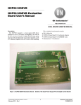
NCP5623C DEMO BOARD BOM – V7.0
TEST CONDITIONS
Power Supply : The system can be powered either by the USB port ( assuming the board is attached to the MCU board using the J1 connector )or by a standard DC power
supply. In any case, one single source of power shall be connected : either the USB or the power supply, but not simultaneously. If a DC power supply is used, make sure it
can supply 500mA continuous output current across the two pins built with connector J2. Make sure the polarity is properly respected : although a built-in zener prevent
for such failure, reverse polarity might destroy the board.
Set up the power supply to any value between 3.2 V minimum to 5.0V maximum. Typically, the supply voltage shall be adjusted between 3.2V – 4.2V to emulate standard
Li-Ion battery.
The NCP5623B being controlled through the I2C port only, an external controller must be provided to send the appropriate commands to the chip. One can select either of the
possible digital sources:
- use an external I2C generator to send the command
- use the MCU board available from ON Semiconductor ( P/N = JB16)
Manufacturing Final Test :
1 - Double check the power supply is set up at 3.6V, maximum rating is 5.0V.
2 – Download the NCP5623B/T demo software into the MCU flash memory. Use the P&E standard hardware and software tools.
3 – Download the GUI program and run it
4 – Turn ON the power supply : the input current shall be in the 4mA to 10mA range, no LED shall be ON. Reset the MCU if necessary by pushing the RESET
button S7
5– Attach the USB connector to the USB port of the external computer. The “USB OPEN” message should be displayed on the bottom, left hand side of the
window.
6– Use the slider, located on the left side of the GUI, to increase/decrease the ILED current: the chip is considered PASS if the brightness of the three LED varies
accordingly to the position of the slider.
7 – Set the ILED current to zero
8– Disconnect the USB port
9- Turn off the power supply to complete the sequence.
At this point, the final test is completed and considered PASS if all the LED have been properly activated.
Digital Control : it is possible to drive the NCP5623T demo board with an ON Semiconductor MCU board and a Window TM based software dedicated to the chip. To
operate such mode of operation, the board shall be connected to the USB port of the host PC with a standard mini USB connector attached to the MCU board USB port.
Page 5 / 13
MB-MAY-18th 2009
5/19/2009
NCP5623C-DEMO-V7