1
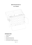
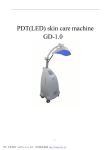
PRO-5050 Remote Sensing Metal Detector Version:2.0/1.0 User’s Manual PACKING LIST The packing box contains following components: One transmitter with battery installed One charger for transmitter One transmitting antenna One piece of connector for transmitter and transmitting antenna One receiver with battery installed One charger for receiver and receiving antenna One pair of receiving antenna One piece of connector for receiver and receiving antenna User ‘s manual GENERAL NOTES To avoid destroying the unit and health injury, don’t pull up the transmitting antenna. To avoid injury, don’t use the detector in severe weather like thunderstorm. To change the setting or the position of the transmitter, shut off the transmitter. Re-turn on it after 15 minutes. Don’t have any electronic devices or metal objects attached to your body (such as cellular phones and pagers). Do not add any metal or other test objects to the area being tested while the transmitter is on. Always check if the battery is enough for operation. Charge the battery if the unit is not in use for over three months. Care must be taken when holding the copper legs and the antenna rods, they may be responsible to damage the user’s eyes. The unit cannot make health injury. But it must be handled away from children. The detector uses micro-sensing for detection. Please do not adjust the components inside the main case. No components in the main case can be adjusted. Do not leave the unit in the sun during hot weather. Keep the unit in cool and dry place to avoid being humid. Keep the unit away from sand. Prevent the unit from excessive shock. Each time after the rods cross, let them contact the ground to discharge the electric charge. ! Please read the user’s manual carefully before use. INTRODUCTION Resonance occurs when an element absorbs energy same to its physical frequency. This theory is adopted in the remote sensing metal detector system. It transmits a stable radio frequency signal and receives the back signal in order to locate the precious metal object. User has to wave arms with traditional metal detector for searching metal objects. Such detector can cover limited surface during operation. It can hardly work in severe conditions. Due to the different principle, the detection depth of traditional detector is very limited. To have a better detection result, our company introduced the advanced remote sensing detection technology. After repeated research and test, we developed this remote sensing metal detector system, i.e. treasure metal directional indicator. It is characterized by searching fast over super large area and depth. Its signal can penetrate in mountain and pass through rivers. It can detect gold(Au), silver(Ag), copper(Cu), lead(Pb), tin(Sn), and jewel. The detector can transmit and receive signal in a large range. The detection radius length can be over 1000 meters. The signal can penetrate 90 meters in the mountain without attenuation. It can detect one piece of silver coin buried in depth of several meters. The operation of this remote sensing detector is simple. Mastering the use of this detector may take some practice. But it is important for getting a successful detection result. COMPONENTS The components include: a case with lock; a transmitter; a receiver and other components. -TRANSMITTER The front of the transmitter has six LED indicators. Each indicator presents a certain frequency and is labeled for a particular element. There is a target selector below the indicators. To the left below the selector, there’s a frequency tuning knob and to the right, there’s a power switch. There are output antenna jack and charging jack at the bottom of the transmitter. Set the Target Selector to the desired target to be detected. The relative LED will light. Normally set the Tuning knob to the middle. As the purity of the test material is different(such as artificial gold and natural gold; copper and bronze), the frequency is different. You can adjust the frequency with the tuning knob. To the left of bottom of transmitter, there’s output antenna jack for connecting the transmitting antenna. To the right of transmitter, there’s charging jack for charging the battery. -TRANSMITTING ANTENNA There are two copper legs and one jack on the transmitting antenna. Before use, plug one end of the connector supplied into the jack on antenna; plug the other end into the Transmitting Signal Output Jack on the transmitter. -RECHARGEABLE BATTERY The unit is powered by one 9V lithium rechargeable battery which is installed in the transmitter. The battery can be used for several years. Before use, please charge the battery for three hours. After the battery is fully charged, it can be continuously used for over 20 hours. When the power LED is dim, you have to charge the battery. -RECEIVER There is Power Switch/Tuning knob at the left top of the receiver. The knob is used to tune the induction. In the middle of the top, there is charging jack. At the right, there is receiving antenna jack. There is a power LED on the front of receiver. When the unit locates metal object, you can adjust the tuning knob to determine the size of the target. Turn the tune knob clockwise to lower the amplitude for determining the location of big targets. Turn the tune knob counter-clockwise to higher the amplitude for determining the location of small targets. -RECEIVING ANTENNA Receiving antenna is sealed copper cylinder. A wire protrudes from the bottom of cylinder. These wires merge to form one wire that terminates with a plug, this plug fits the jack on the receiver. The antenna consists of two metal rods. They can swing freely. HOW TO USE THE ANTENNA RODS Take one antenna rod in each hand. Hold them in front of your chest. Hold hands about 25-30cm apart. Start with the ends of the rods forward and parallel and tilted slightly downward about 2cm. Walk at a normal space. Do not raise or swing the rods. Practice walking with rods until you can walk without swinging them. Mastering the use of the rods may take some practice, but it is one of the key skills needed to effectively use your system. -CHARGER A special battery charger is supplied for the receiver. Battery should be charged for three hours before use. When the power LED is dim, battery should be charged. When you’re familiar with these components, you can start field test. The test field should be far away from urban area to avoid high voltage lines, railway line, signal tower. The field should not exist of metal fragments. REGIONAL TEST To field test the system, place transmitter on the ground, connect transmitter with transmitting antenna. Plug one end of connector into the corresponding receptacle on antenna and the other end into the antenna jack on transmitter. Dig a small hole about 10cm deep to inject the copper rods in the ground. In hard and dry ground, you can water slightly to prevent any damage to copper rods. Bury test object( gold, silver or copper) about 30 to 50 meters from the transmitter. Set the target selector to the desired target. Set the tuning knob to middle position. Never plug in or unplug antenna while transmitter is on. Otherwise it will cause damage to the system. Connect the receiver with receiving antenna. Power on the receiver. After 5 minutes, holding the rods, as practiced, walk a circle around the transmitter, staying about 5-10 meters from the transmitter. Make sure the receiver and receiving antenna are on. Picture A Picture B When you are on the line between the antenna and the test target, the rods should cross(As you can see on Picture A). At this time the signal line is generated between transmitter antenna and the test target. Mark where the rods cross. As you pass over the line, the rods will uncross(As you can see on Picture B). Choose one method to track the metal target. Do not add any metal or test objects to the area being tested while transmitter is on. To get better test result, you can adjust the frequency with Frequency Tuning knob. Note: Each time after you adjust the tuning knob, you’d better wait a moment before re-starting the test. FIELD TEST After you determine the test field, you can repeat the steps described in REGIONAL TEST. Note: Wait 15 minutes before starting formal test. If the test is successful, you can turn off the transmitter and take out the test target. SIGNAL TRACING There are three ways ( S route, Cross, Triangle) to trace the signal line. -S ROUTE WAY Firstly walk a circle away from the transmitter antenna (shown as bellow fig.) to find the signal line. Then trace the line by walking in “S”. The receiving antenna rods cross above the signal line( make mark each time the rods cross). When you deviate from the signal line, the rods will stop crossing. When you pass over the target and continue to move forward, the rods will not cross any more. In this way, you can determine the location of the target. When you approach the target, you may find another target, if these two targets are close, the system will indicate a big target. In S route, you can bypass trees or other obstacles. -CROSS WAY Walk a circle at 5-10 meters away from transmitter. When you are on the line between the transmitting antenna and the test target, the receiving antenna rods will cross. At this time, a signal line is generated. Mark where the rods cross. As you deviate the line, the rods will uncross. Now move another 10 meters away from the transmitter. Repeat the process, again mark where the rods crossed. By drawing a straight line from the transmitter through the places you marked, you will have your X Axis. Shut off receiver and transmitter. Wait 15 minutes, then move the transmitter and antenna to a new location, repeat the above process. The line that is developed this time will be your Y Axis. The place where the X Axis and Y Axis intersect is your target location. -TRIANGLE WAY This detection way is suitable for inaccessible areas. Firstly follow the above steps to find a signal line. Then remove the transmitter to the left or right of its first place. Repeat the process of searching target to form new signal line until this line is just 45 degree from the first line. And the distance from the transmitter to its original location is just same as the distance between the test target and the original location of transmitter. DETERMING DEPTH If the target has been buried for long time (over two years), an energy “sphere” is generated over the target. The target is located vertically below the “sphere”. You can approach the suspected target from 2 opposite directions, for example right/left(relative to energy transmission line). As soon as you reach the limit of target energy “sphere”, the rods cross. Mark the spot where rods cross. Half the distance between the 2 opposite indications is approximately target depth. This method is usable for target buried over 2 feet, but not suitable for target shallowly buried. INTERFERENCE SIGNAL AND COUNTER MEASURES Low battery, magnetic fields due to macula, magnetic storm will affect the signal. At this time, you have to wait until signal appears. If the signal is not stable, you can adjust the frequency with TUNING knob. Different person has different conductivity on body. So they may have different detection result. For example: (1) Two rods point to the target instead of crossing. (2) Only one rod points to the target. (3) Someone passes the energy line, but he got slower reflection signal. In this case, user should walk slowly. Make sure the rods swing freely and tilted slightly downwards. The size of target, the buried time, and the electrolyte of soil will affect the detection. In some cases, Even target was taken out, the detector will still have reaction to the spot where it was once buried for long time. This is the ghost signal received by the detector. During the detection, user can try to solve the problem in following ways: Check if the battery is enough, if the charger is in good condition. If the charger is ok, the LED will light when in charging. Check if the target indicator is ok. When desired target is selected, the corresponding LED will light. It is suggested following X and Y cross way to find the exact location of target buried in more than 10 meters’ depth. For better detection result, user had better try to approach the target several times from different directions. ADDITIONAL INSTRUCTION 1. Wait 15 minutes after the main unit is powered on. 2. Do not plug in the antenna if misturn on the unit. 3. Hold the antenna rods 20 inches apart and tilted down to avoid misreading. 4. In highly mineralized area, the detector will have lower sensitivity. 5. The best detection time is morning or evening. 6. Don’t stop the rods crossing before going on other operation. 7. Don’t operate the detector with gloves. 8. Using the unit with other detection device will be helpful improve the efficiency of detection.